
An animated GIF of the single USB RGB LED cycling through red, green, and blue.
This project is a single RGB LED that is controlled over USB using a command line interface from a serial terminal window. A PIC16F1459 microcontroller implements the USB communications device class (CDC), processes the commands received from the user, and controls a single APA106-F8 8mm round RGB LED.
The USB CDC causes the PIC to appear as a serial port to the host computer. At this point, any terminal emulator software can be opened to access the CLI, and send commands to control the color and brightness of the LED. The APA106 addressable LED protocol is identical to the Neopixel / WS2812b protocol.
Related Projects
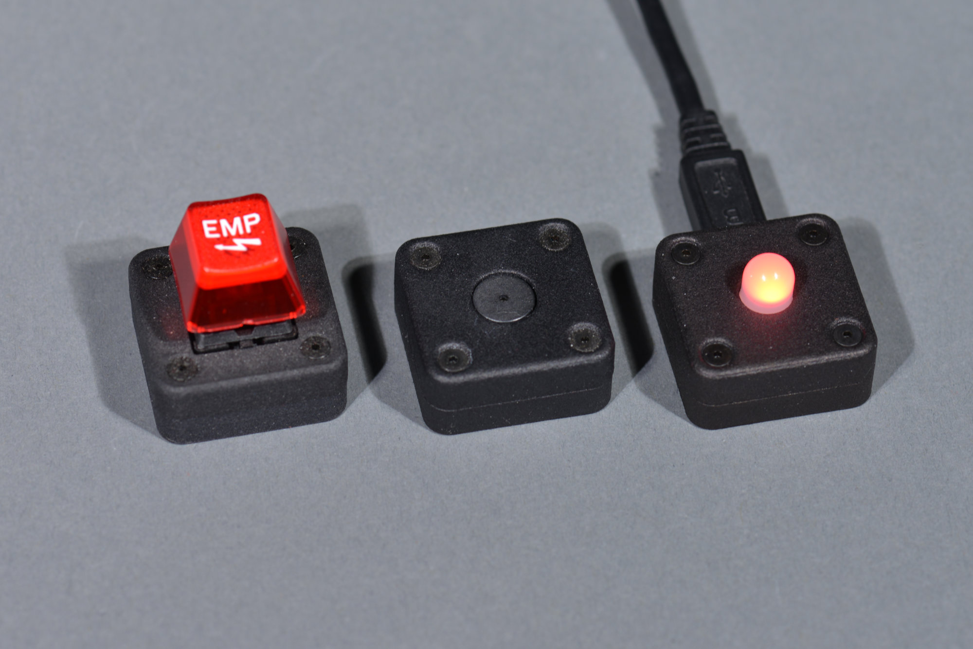
The family portrait. They’re all so useless! I mean cute. They’re all so cute!
This is the third project in my series of near useless, single-purpose USB devices. The first device was a single-key keyboard that ostensibly could be used to replace the missing escape key on touchbar MacBook Pros. The second device was an annoying caps lock warning buzzer that would sound a tone to warn you if you accidentally engaged caps lock. We made a video about the caps lock buzzer at work.
For this project, I used the same PIC16F1459 microcontroller that’s used in the previous projects, but replaced the key switch and buzzer with an addressable RGB LED. Early in the design process, I experimented with using a WS2812b SMD RGB LED and several different possible lenses and diffusers. Ultimately I decided to use an APA106-F8 through hole RGB LED because its 8mm diameter translucent case negated the need for a separate diffuser and simplified the mechanical design.
Prototyping the Single USB RGB LED
I needed to prototype this project before designing a board because I wasn’t sure how the PIC16F1459’s USB software functions would interact with a blocking function bit-banging out the WS2812b protocol. Spoiler: it worked out fine!
Scrounging for Hardware
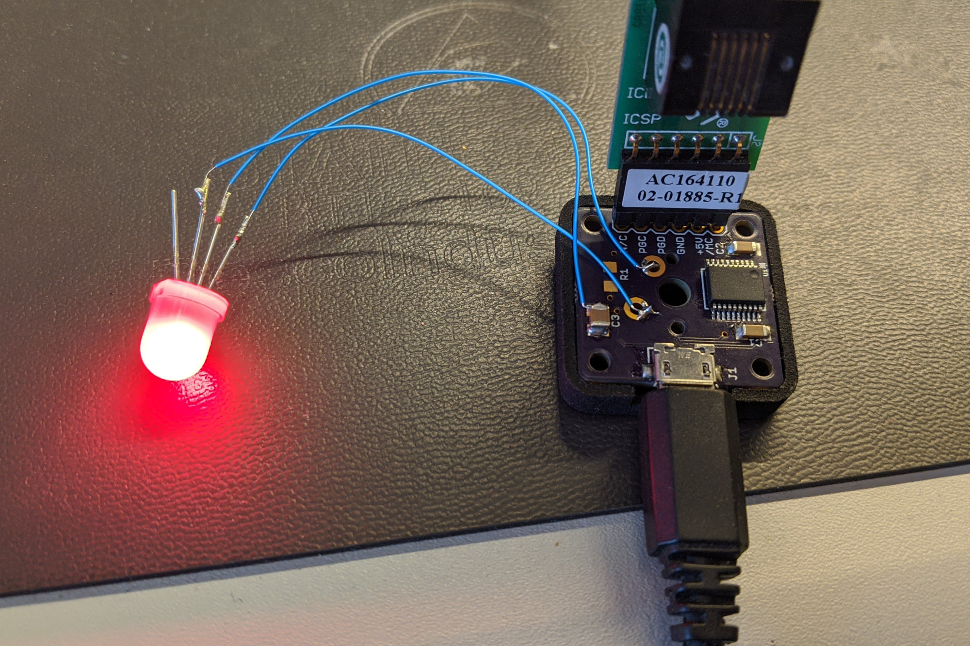
The prototype hardware with debugger attached.
Digging through a bag of old single key keyboard boards and parts, I found a board that was stuffed with all the components except the keyswitch. A quick check of the schematic and I found ground, +5V, and an easily accessible microcontroller GPIO pin on the board. I also had a bag of APA106-F8 LEDs left over from a previous project. I dug one out and tacked some blue wires between the APA106-F8’s leads and the GPIO, ground, and +5V points on the board.
Picking a Starting Point for the Software
For the software, I had two pieces of code that I could use as starting points. The first was the implementation of the USB CDC stack with a simple CLI for the PIC16F1459-based USB stack light controller. The second was a bit-banged implementation of the WS2812b protocol for the Ethernet-powered Christmas tree project.
I copied the stack light controller software to a new project in the MPLAB X IDE and added copies of the WS2812b files from the Ethernet pixels project to the new project. I replaced the calls to the I2C and PCA9685 functions that controlled the stack light in the old project with calls to the WS2812b functions to control the LED in the new project. It compiled, it downloaded, and the LED behaved…erratically.
Debugging the WS2812b RGB LED Protocol
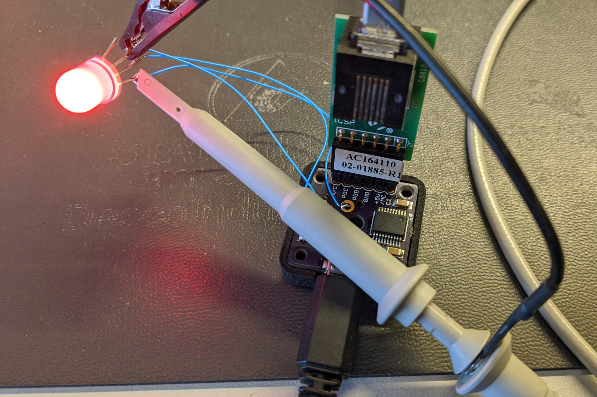
Probing the LED data signal.
I hooked up a scope probe to the data and ground lines on the LED and observed the implementation of the WS2812b protocol on the oscilloscope. The ‘0’ high time was wrong, the ‘0’ low time was wrong, the ‘1’ high time was wrong, and the ‘1’ low time was wrong. It was all wrong.
        // Bit 7
        if (a & 0x80) {
            WS2812b_LAT = 1;
            NOP();
            NOP();
            NOP();
            NOP();
            NOP();
            NOP();
            NOP();
            WS2812b_LAT = 0;
        } else {
            WS2812b_LAT = 1;
            NOP();
            NOP();
            NOP();
            WS2812b_LAT = 0;
            NOP();
            NOP();
            NOP();
            NOP();
        }
I dug into the WS2812b code some. A portion of the code is reproduced above. I inserted more NOP instructions into the code then moved them around the instructions that set the WS2812b data line high and low until I had something that mostly met the high and low time specs in the WS2812b data sheet and that worked reliably.
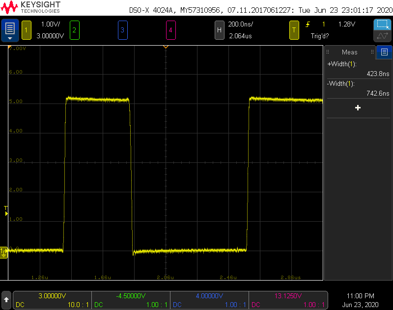
Timing for a zero.
The scope screenshot above shows the timing for sending a ‘0.’ The high time is 423.8 ns and the low time is 742.6 ns. According to the data sheet, these should be 400 ns and 850 ns +/- 150 ns respectively. My timing for a ‘0’ meets the data sheet spec.
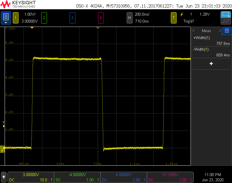
Timing for a one.
The scope screenshot above shows the timing for sending a ‘1.’ The high time is 757.6 ns and the low time is 659.4 ns. According to the data sheet, these should be 800 ns and 450 ns +/- 150 ns respectively. The high time meets the spec; the low time does not. Fortunately, WS2812b LEDs are not that sensitive to the low time between pulses, so this will work reliably
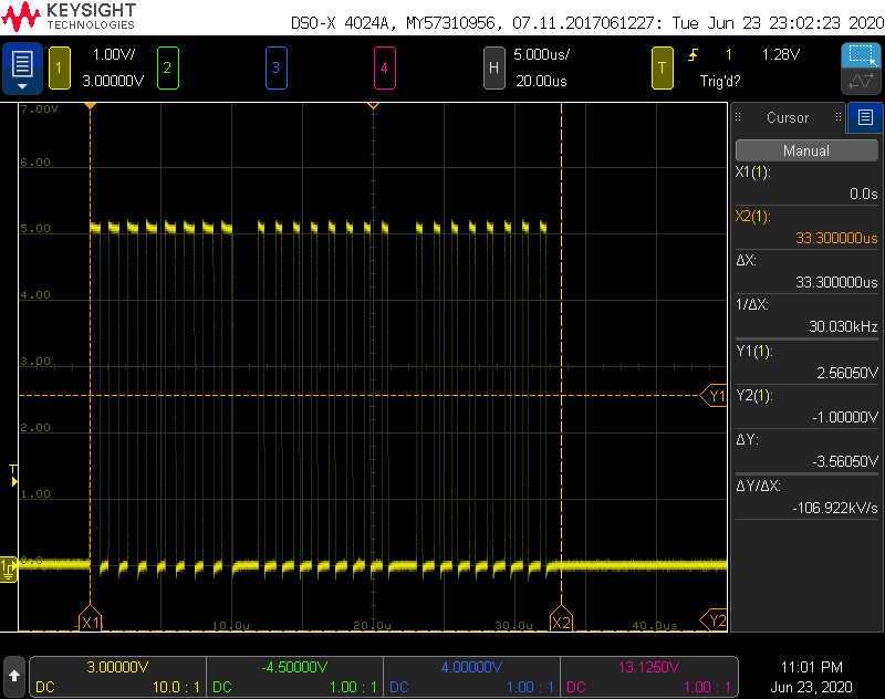
Time to send all 24 bits.
USB runs on a 1 ms heartbeat. The time to send 24 bits of RGB data to the LED needs to be much less than 1 ms to ensure the USB host and USB device stay connected. Looking at the scope trace above for sending 0xFF0000 to the LED, the total time is 33.3 us. This is much, much less than 1 ms so the USB host and USB device should stay connected.
Late update: note that there is a data sheet for the APA106-F8 LEDs and that it specifies different timing than that in the WS2812b data sheet. The APA106-F8 LEDs, however, appear to work fine with the WS2812b LED timing I’m currently using.
Designing the Hardware
I started with the annoying caps lock warning buzzer as the starting point for the hardware for this project.
Schematic

The completed schematic.
I copied the Eagle project for the annoying caps lock warning to a new project and made a few edits. The resistor, transistor, diode, and buzzer were removed. These were replaced with a single APA106-F8 RGB LED. The new schematic is shown above.
Board
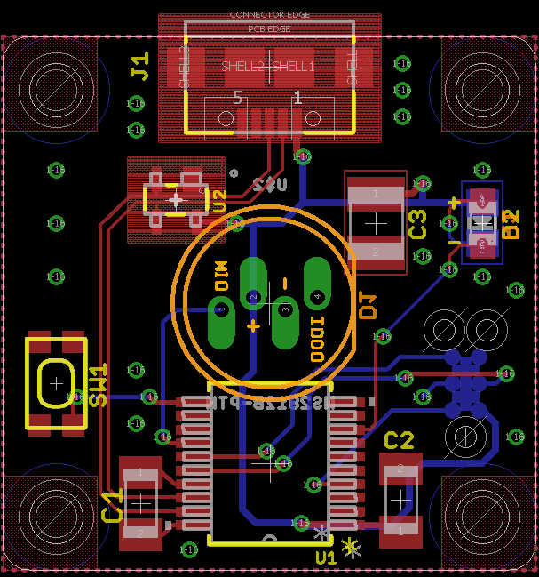
The completed board layout.
The board is identical to the board for the annoying caps lock warning buzzer except the buzzer, transistor, resistor, and diode have been replaced with an APA106-F8 LED. I started with the footprint for the APA106-F8 LED from a SparkFun LED library but reworked the location of the pins, part origin, and device outline to reflect reality. I also added signal labels to the silkscreen layers on each side of the board. I exported the Gerbers and uploaded them to OSH Park for manufacturing.
Designing the Enclosure
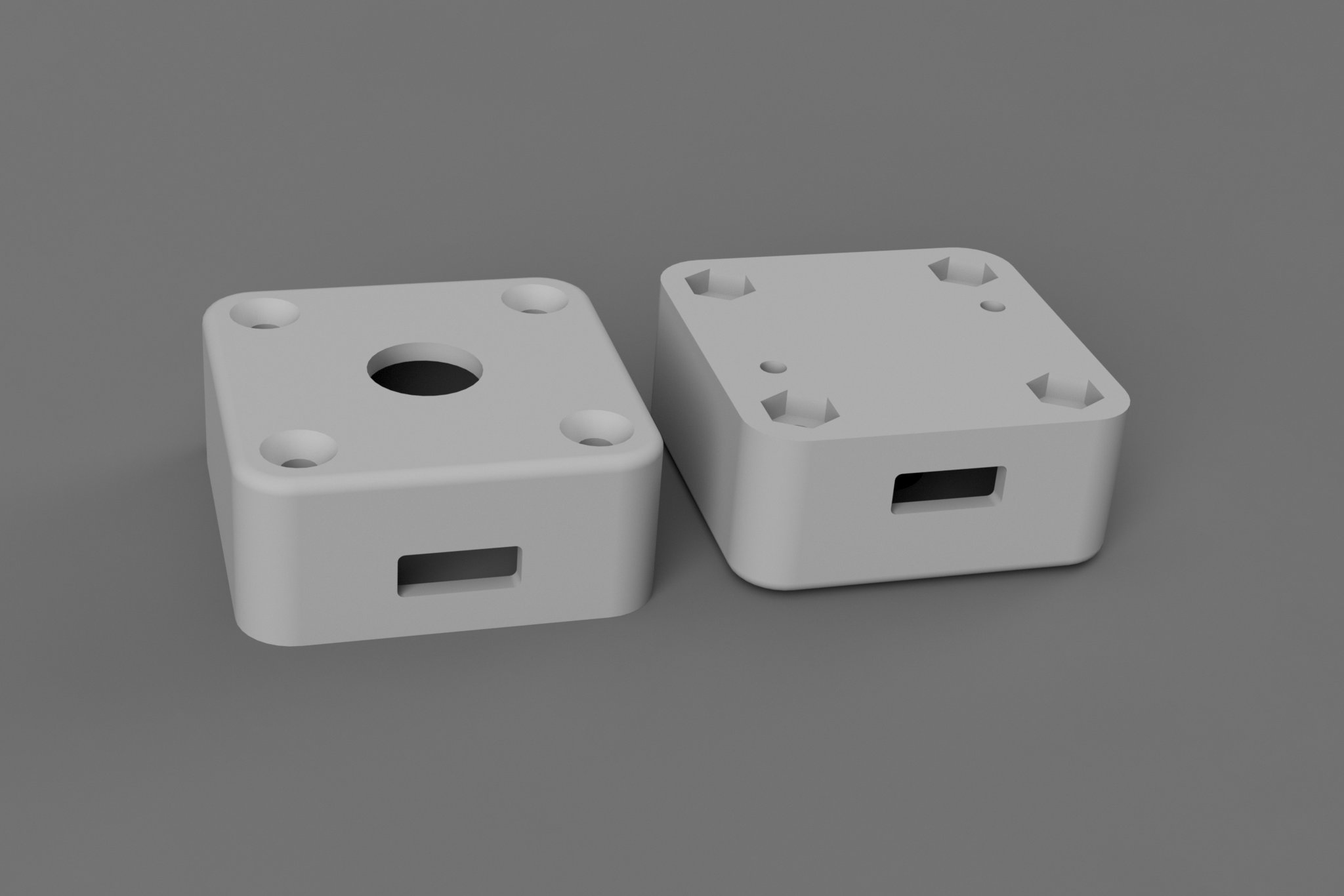
The completed enclosure design. It’s the same as annoying caps lock warning buzzer except for the diameter of the hole in the center of the top.
The enclosure is identical to the enclosure for the annoying caps lock warning buzzer except the central 10 mm hole for the buzzer was replaced with a 8.25 mm hole for the LED.
The enclosure has a cutout for the USB connector, countersinks for the flathead screws, and recesses to accommodate hex nuts. On the bottom are two holes. One is for a status LED and the other is for a small pushbutton to force the device into bootload mode at power up for firmware upgrades.
I exported the STL files for the enclosure from Autodesk Fusion 360 and uploaded them to sculpteo.com for manufacturing using HP Multi Jet Fusion 3D printing process. Be sure to use the part orientation feature to orient the parts with the most-visible surfaces down on the print bed. This means the top of the enclosure is oriented upside down on the print bed and the bottom of the enclosure is oriented right side up on the print bed.
Assembling the Project
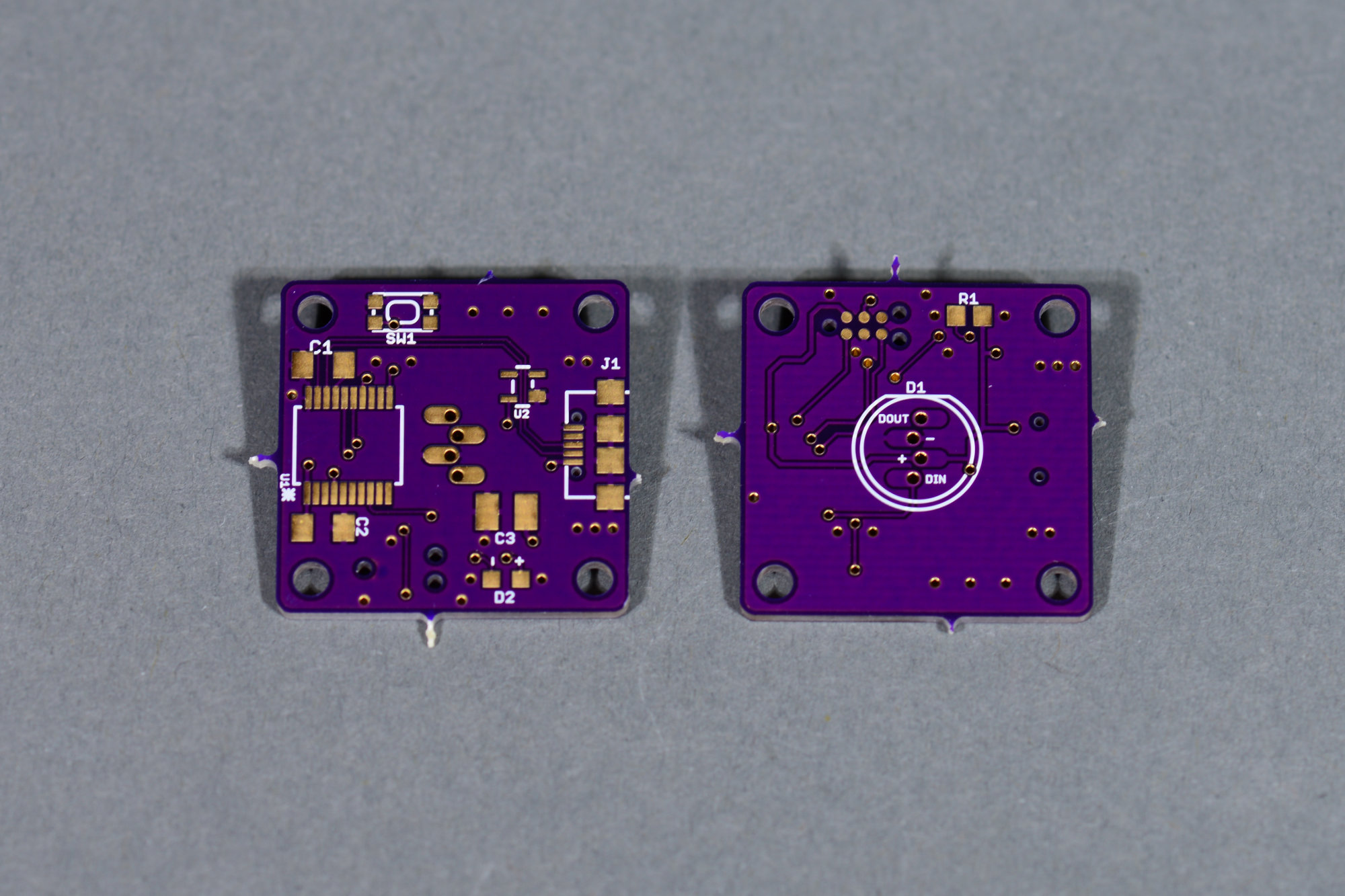
Unstuffed boards fresh from OSH Park.
On Saturday, June 27, 2020, I received the completed boards back from OSH Park.
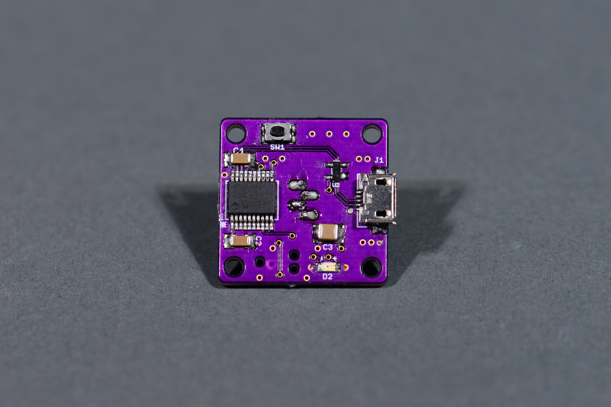
Stuffed board bottom.
Saturday night I stuffed all the components on the board starting with the top of the board (which confusingly enough will be placed top-side down in the enclosure).

Stuffed board top.
I then placed the 1k resistor on the bottom of the board and very carefully inserted, positioned, and soldered the LED in place.
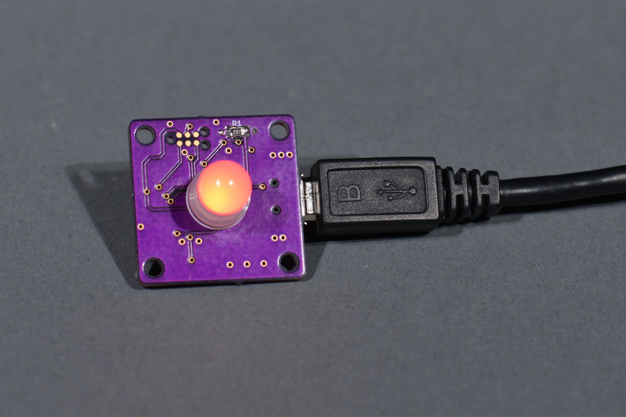
Testing the electronics before mounting them in the enclosure.
After building the board, I tested the board to make sure all was functional before placing it in the enclosure. The production board uses different GPIO pins on the PIC16F1459 versus the earlier prototype. I had to change the pins connected to the small button, the LED on the back of the board, and the main APA106-F8 LED in the software before I could do any testing.
Once these changes were made in the software, I connected the assembled board to a USB port on my computer and programmed the firmware using my MPLAB REAL ICE programmer and a Tag-Connect programming cable. I opened a terminal emulator to the board and could control the color of the connected LED. Success!
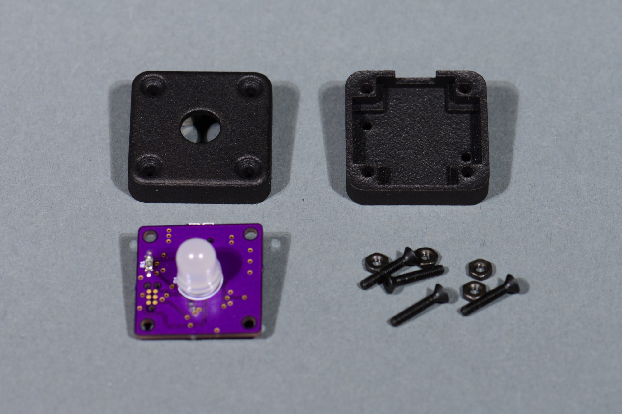
All the pieces for the project are about to come together.
On Monday, June 29, 2020, the 3D printed enclosure arrived. If you look at the bottom of the enclosure in the right-hand side of the photo, you can see sharp edges on all the surfaces. Contrast this with the smooth edges on the top of the enclosure in the left-hand side of the photo.
This is caused by the orientation of the part in the print bed and the printing process. The edges on the surfaces toward the bottom of the print bed are softened while the edges on the surface facing up in the print bed are sharpened. I tend to print my parts with the surfaces exposed to the user facing down in the print bed.
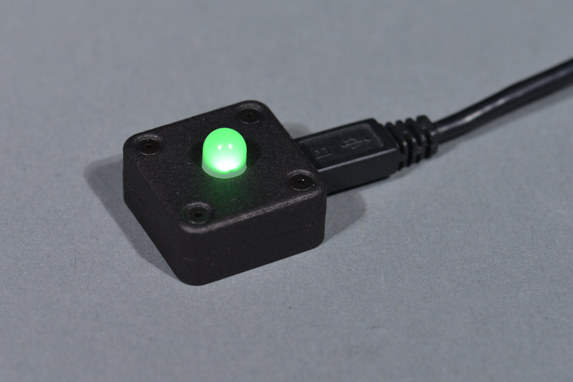
The completed and assembled project.
I assembled the unit using four 2-56 x 1/2″ black oxide socket head cap screws and four 2-56 black oxide hex nuts. The completed unit is shown in the photo above.
Testing

A Tera Term window connected to the single USB RGB LED.
To test the single USB RGB LED, I used Tera Term to connect to the serial port assigned by my PC to the USB RGB LED. In this case, COM41. The bit rate doesn’t matter. It’s ignored by the CDC stack on the PIC.
To set a color, just enter its hex value a the CMD> prompt and hit return. If you make a mistake, the delete key can be used to back up and change your entry. If you still make a mistake, usually the worst that happens is you get an unexpected color.
Finishing Touches and Next Steps
I’d like to try adding a 100k pull down resistor on the LED data signal to see if this would keep the LED from lighting up on power up. I also need to flash the bootloader and rebuild the software to support the bootloader. This would permit software updates without having to disassemble the unit. Finally, I’d like to add a random blinking mode that would blink the LED random colors without intervention by the host PC.
Bill of Materials
The complete bill of materials for this project is listed below.
| Line # | Mfr. # | Manufacturer | Description | Order Qty. |
| 1 | C1206C474K5RACTU | KEMET | 50V 0.47uF X7R 1206 10% | 1 |
| 2 | C1210C105K4PACTU | KEMET | 16V 1uF X5R 1210 10% | 1 |
| 3 | C1206C104J4RACTU | KEMET | 16V 0.1uF X7R 1206 5% | 1 |
| 4 | 629105136821 | Wurth Elektronik | USB Micro B | 1 |
| 5 | PIC16F1459-I/SS | Microchip | 8-bit MCU | 1 |
| 6 | CR0805-JW-102ELF | Bourns | 0805 1K 5% | 1 |
| 7 | KMR211NGLFS | C&K Switches | Tactile Switch | 1 |
| 8 | PRTR5V0U2X,215 | Nexperia | 5.5V ESD Protection Diodes | 1 |
| 9 | 599-0130-007F | Dialight | 0805 Orange LED | 1 |
| 10 | APA106-F8 | Unknown | Addressable through-hole 8mm RGB LED | 1 |
| 11 | 91253A081 | McMaster Carr | 2-56 x 1/2″ black oxide socket head cap screws | 4 |
| 12 | 96537A110 | McMaster Carr | 2-56 black oxide hex nuts | 4 |
Design Files
The software, board, and enclosure design files for this project are located in my single-usb-rgb-led repository on Github.