
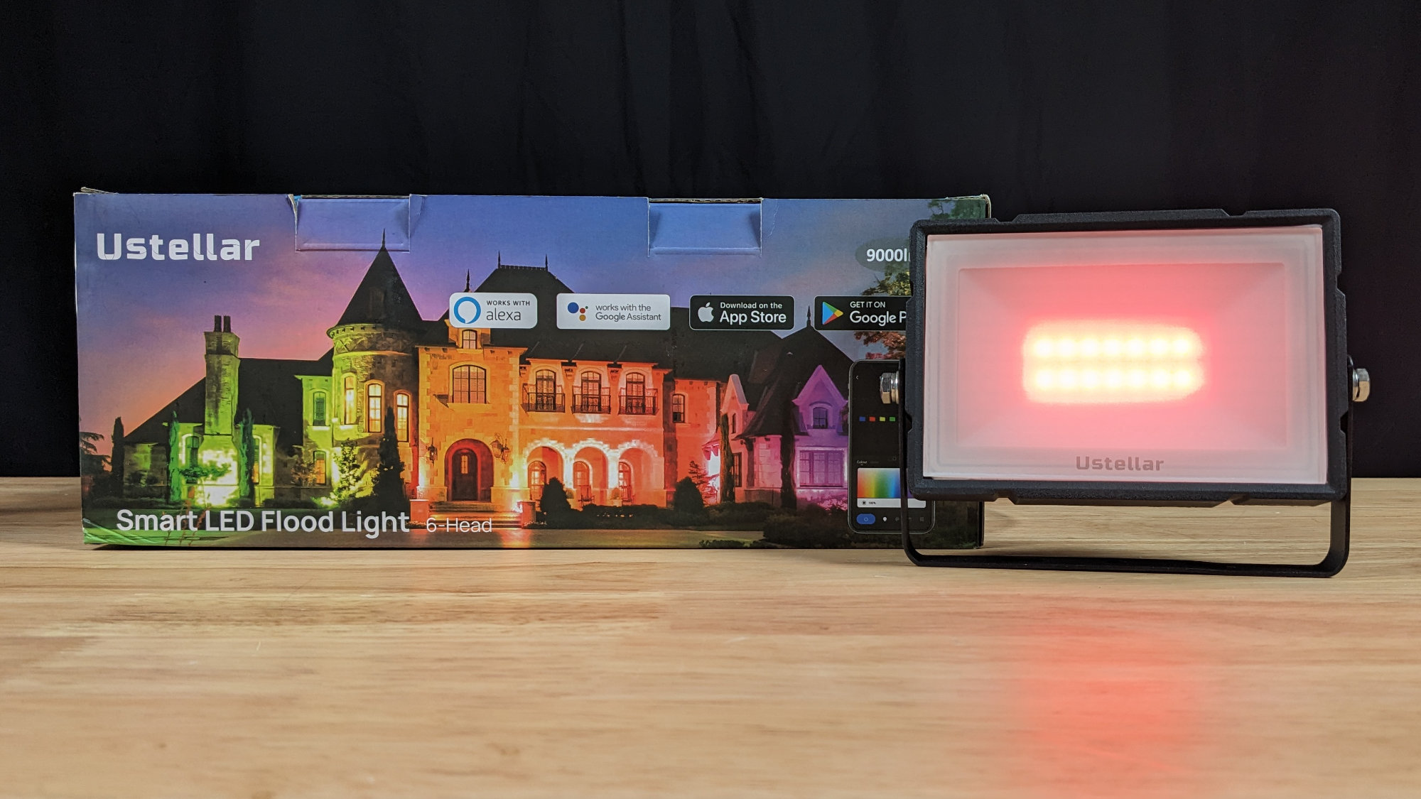
The Ustellar 100 W light set box and one of the lights.
In my my last post, I looked at four different sets of inexpensive LED flood lights to see which could be controlled using WLED. While they all could be controlled with WLED to some extent, only some could take advantage of WLED’s extensive library of built-in effects. In this post, I’m going to take a detailed look at the 100W version of Ustellar’s GemBand set of six RGBW smart flood lights. It’s a little different than the previous sets but can still be controlled with WLED with one pretty big caveat.
Disclaimer: Glen may earn compensation for sales from links on this post through affiliate programs.
Detailed Description of the Lights
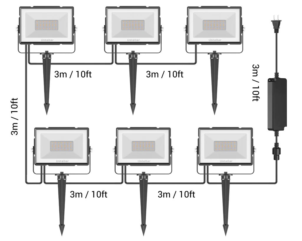
Diagram from Ustellar’s website showing the major components of the six flood light set.
The set of lights includes a power adapter and six flood lights. There’s a connector between the power adapter and the first light. The rest of the lights are permanently attached to each other with 3 m of cable from one light to the next. The diagram from the Ustellar website shown above is accurate.
At the end of my previous post, I outlined a list of five rules for finding lights that potentially use the WS2811 protocol and could be compatible with WLED and other pixel controllers. This set potentially violates two of those rules. First, there’s not a separate controller between the power supply and the lights. Second, from the diagram, photos, and videos, I couldn’t tell if the connector between the power supply and the first light had two, three, or more pins. I went ahead, took a risk, and bought the set.
I purchased my set of lights direct from Ustellar’s website for $123 but they’re available on Amazon for as low as $159.99 minus a $50 coupon.
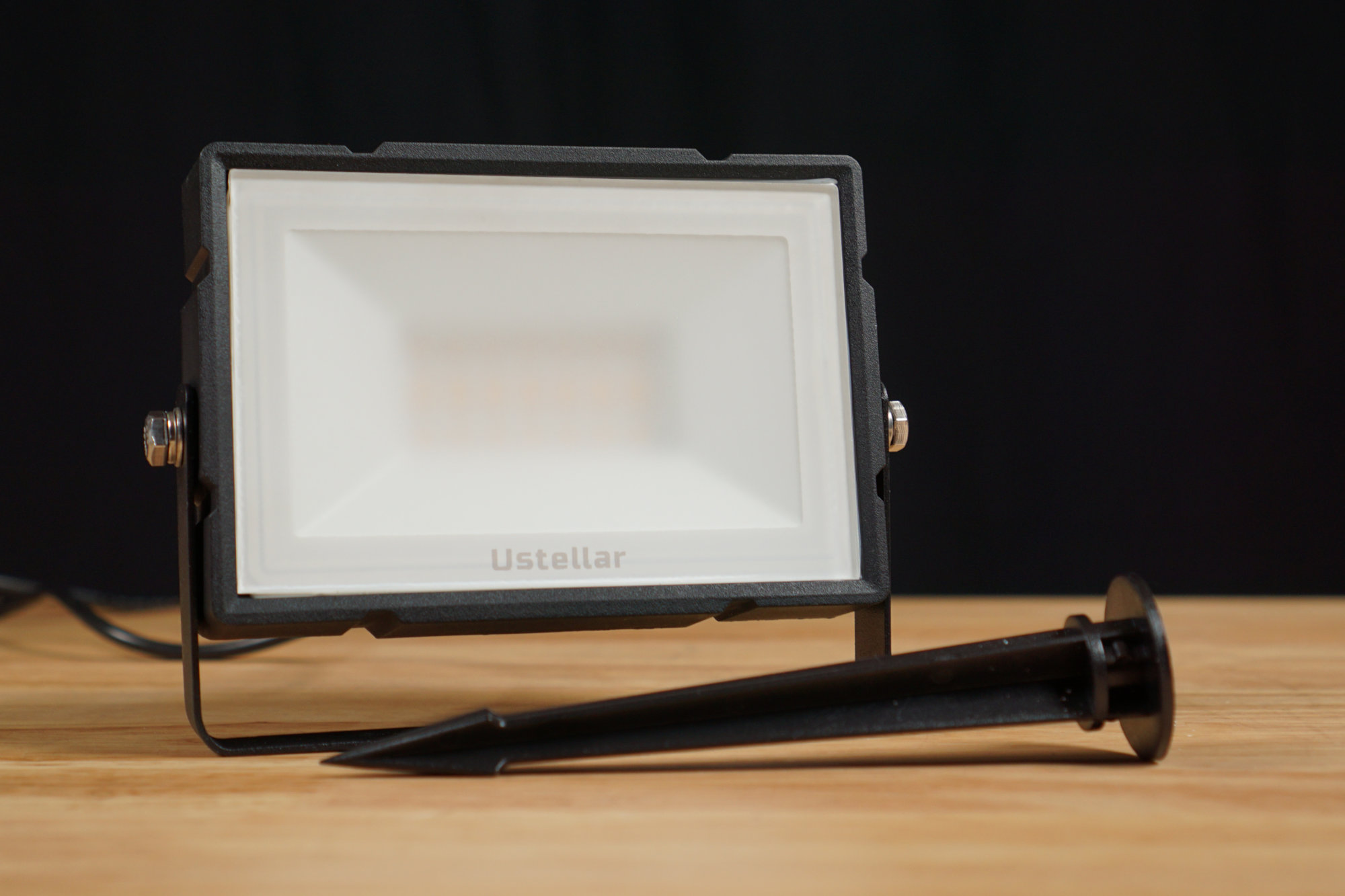
One of the aluminum and glass flood lights and its plastic ground stake.
Each light is housed in a sturdy one-piece aluminum enclosure with a frosted glass front. The lights measure about 150 mm x 100 mm and contain 6 rows of LEDs distributed as 4 rows of warm white LEDs and 2 rows of RGB LEDs. The is exactly double the number of rows and LEDs as the 40 W version. The glass is sealed to the aluminum enclosure with adhesive making non-destructive disassembly highly unlikely. The included ground stakes are plastic so use an old screwdriver or similar to start the hole before whacking at the stakes mercilessly with a rubber mallet.
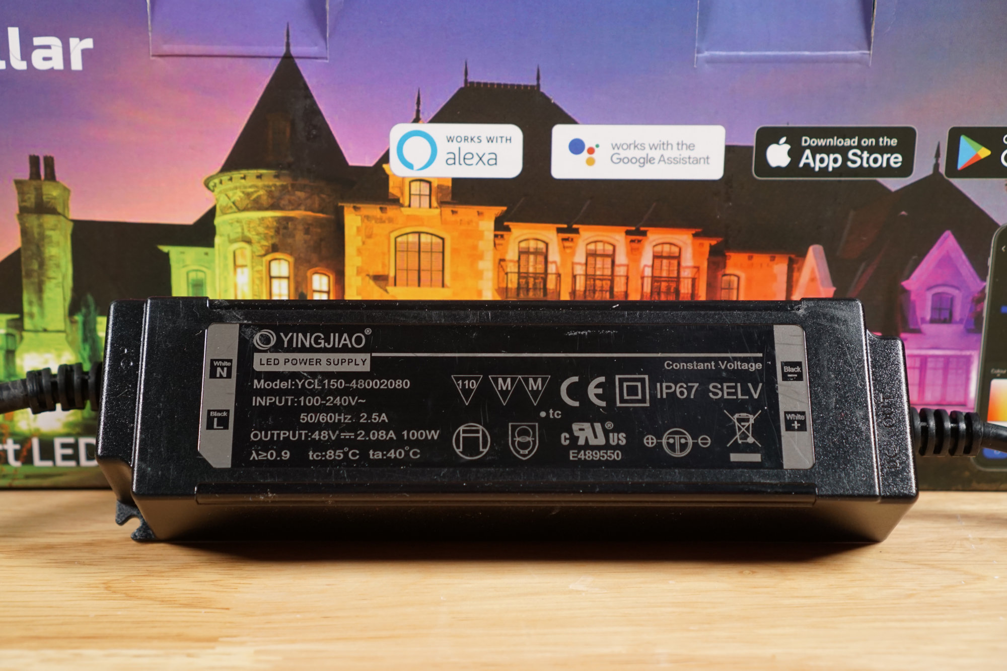
The included 48 V 2.08 A / 100 W power supply.
The 48 V at 2.08 A / 100 W power supply is a sealed waterproof brick. The manufacturer and model number are listed on the supply and there’s a public, real datasheet available on the manufacturer’s website. This power supply does appear to be customized somewhat for Ustellar though.
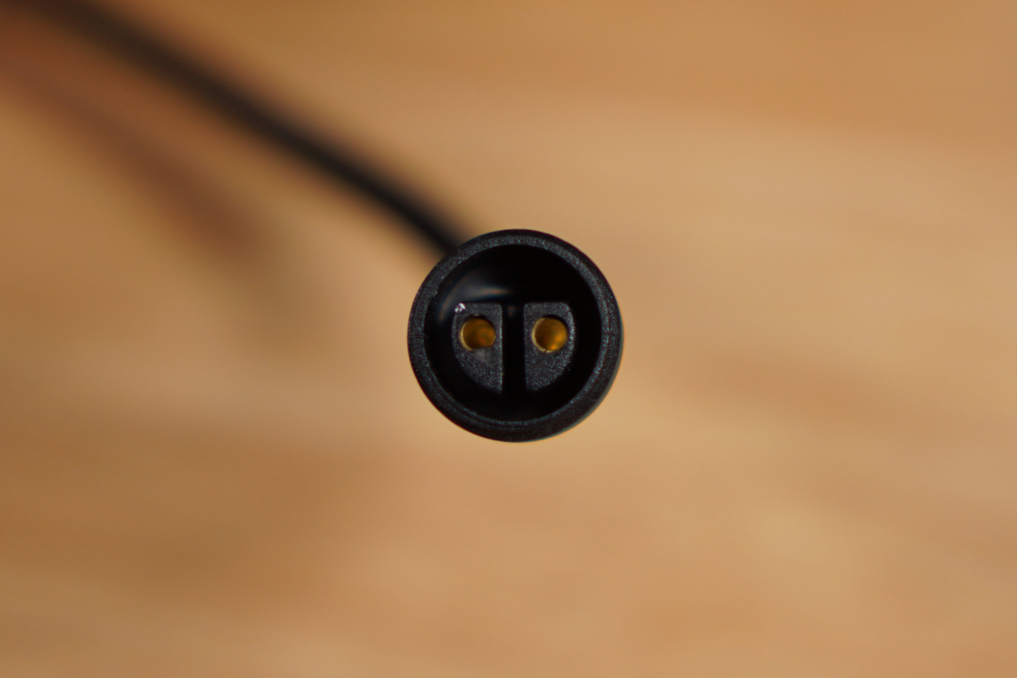
The two-pin connector on the cable from the power supply.
The input side of the power supply uses a standard two-prong North American AC line cord. The output side of the power supply uses the two-prong connector shown in the photo above. This connects to the mating connector on the power cord from the first light in the string. Both cords are permanently attached to the power supply.
Looking back at the markings on the edges of the top of power supply, the line cord has line and neutral and the output cord has DC (+) and DC (-). This appears to be a simple power supply rather than a power supply with a built-in wireless receiver and controller for the lights.
If the controller is not in the power supply, that leaves open two possibilities:
- There’s a wireless receiver in the first light and the remaining lights follow commands from the it.
- There’s a wireless receiver in every light.
If it’s the first possibility, maybe I can still use 5 of the 6 lights. If it’s the second, well, I’m going to need to visit a local glass shop to get some new glass cut to make use of any of the lights. Time to do some research.
Research
I couldn’t find much information on the 100 W version of the light set. I did find lots of information on the 40 W version of the light set and my hope was the 100 W set would function similarly.
Setup Video
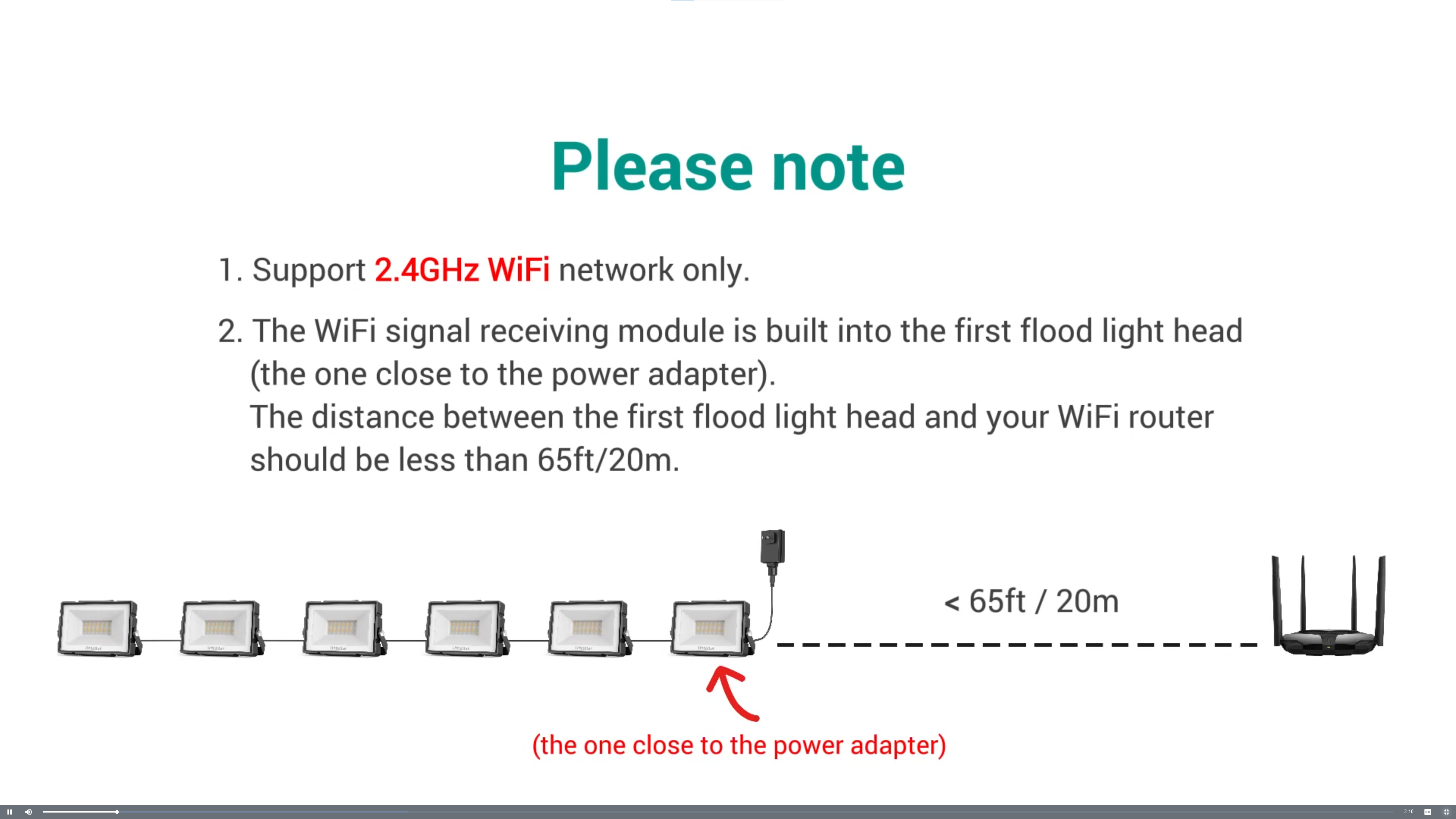
A frame from the instructional video for the 40 W set of flood lights.
First up, I found a video on how to set up the lights. The most interesting part of the video is shown in the screen capture above. This image strongly implies there’s only a single wireless receiver / controller and it’s located in the first light in the string.
FCC Filings
Next up, I headed over to fccid.io to search for the FCC filings for the light. The FCC ID on the tag on the power supply is 2AWONUT88875. Despite this power supply only being for the 100 W light set, the indicated FCC ID was for the filings for the 40 W version of the set. Better than nothing I guess.
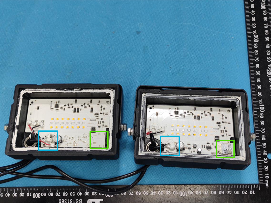
An internal view of two of the flood lights from the 40 W set. The light on the right is the first light in the chain. The light on the left is representative of the remaining flood lights.
One of the internal photos from the FCC filing is shown above. I added the green and blue boxes on to the photo. The light on the right is the first light in the chain. The light on the left is representative of the remaining flood lights.
If you look inside the green boxes, there’s only a wireless module in the first light. The remaining lights do not have a wireless module. If you look inside the blue boxes, there’s only two wires connected to the input of the first light but three wires connected to the input of the second light.
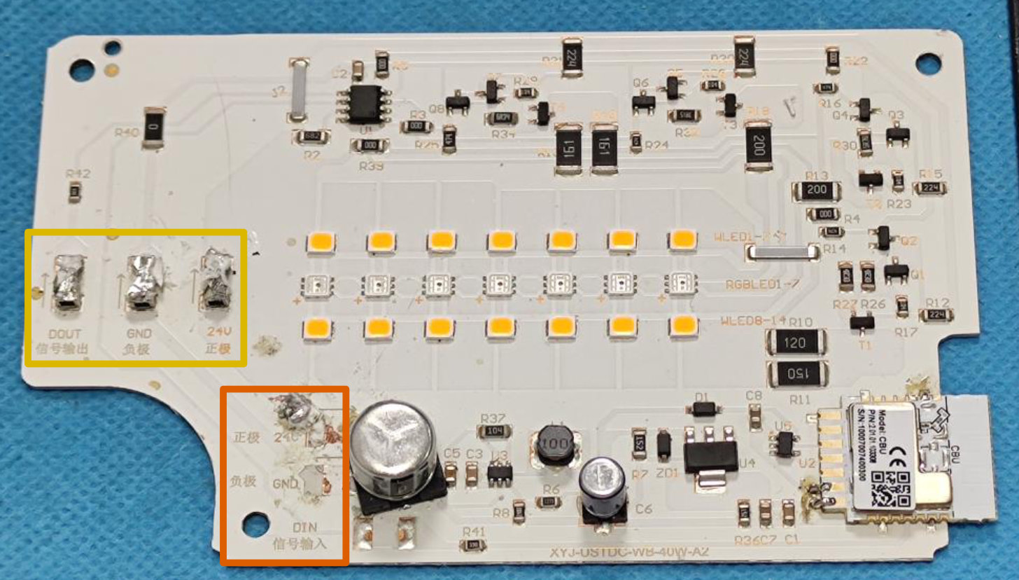
Circuit board from one of the lights with the power and data inputs highlighted in orange and the power and data outputs highlighted in yellow.
The power and data input and output terminals are shown inside the orange and yellow boxes I added to the 2nd internal photo shown above. On the first light, the black and white wires from the power supply are connected to the 24V and GND inputs and there’s no connection to the DIN terminal. There is, however, a connection to the DOUT terminal. On the second and subsequent lights, the black, white, and red wires from the output of the previous light are connected to the 24V, GND, and DIN terminals of the next light.
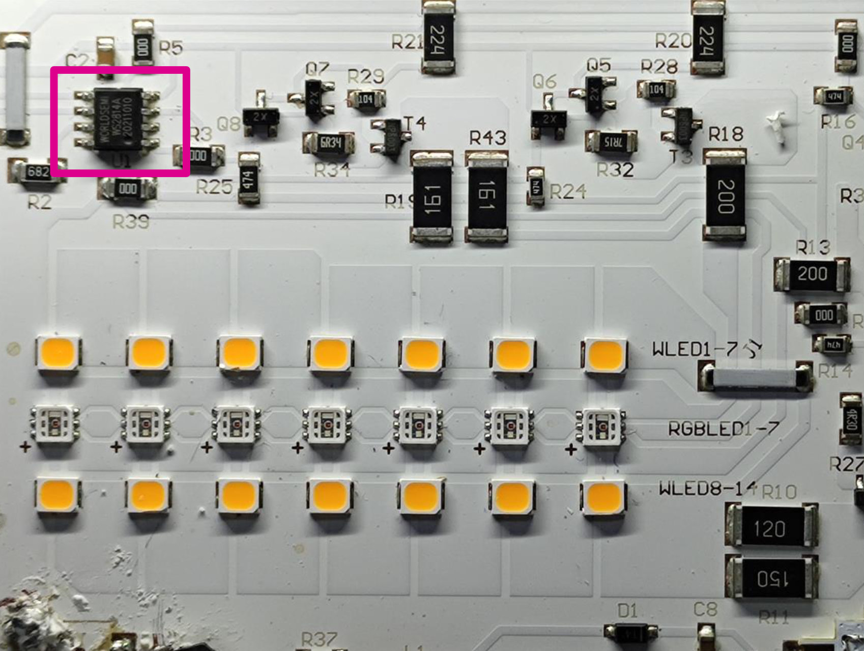
Circuit board from one of the lights with a WS2814 four-channel LED driver highlighted in magenta.
At this point, I felt safe to assume that only the first light contains a wireless receiver and controller and the remaining lights are controlled by the first light. I still did not know what the protocol was until looking at the third internal photo shown above. Yep, inside the magenta box is a WS2814 four-channel LED driver.
By the way, the wireless module is a BK7231N but it would be difficult to flash custom firmware on it since you must either break the glass to get to the programming terminals or figure out how to do an unauthorized over-the-air update.
Digging into My 100 Watt Set
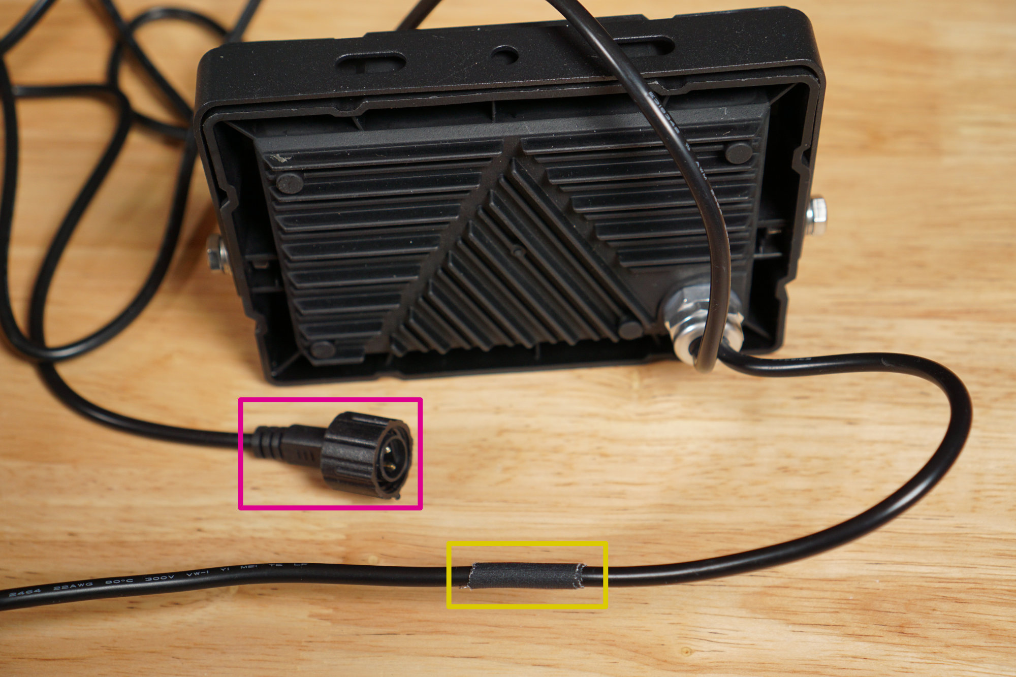
One of my lights from the 100 W set with the power connector highlighted in magenta and my surgery to discover how many conductors in the cable to the next light highlighted in yellow.
I felt pretty confident at this point that at least five of the six lights used the WS281x protocol and could be controlled via WLED. Of course, all the information I had was for the 40 W set and the big question was if the 100 W kit worked the same as the 40 W kit. If the wire between the first and second light was three conductors, I was golden. If it was only two conductors, this 100 W set functioned differently than the 40 W set and I’d need a new plan.
Counting the Conductors
I noticed the two conductor wire from the first light to the power supply was more flexible and had a tighter bend radius than the wire from the first to the second light. This was a good sign there was at least one more conductor in the wire between the lights. I used a knife to make a quarter inch slit in the outer insulation jacket and peeked inside. Sure enough, three wires!
Discovering the Protocol
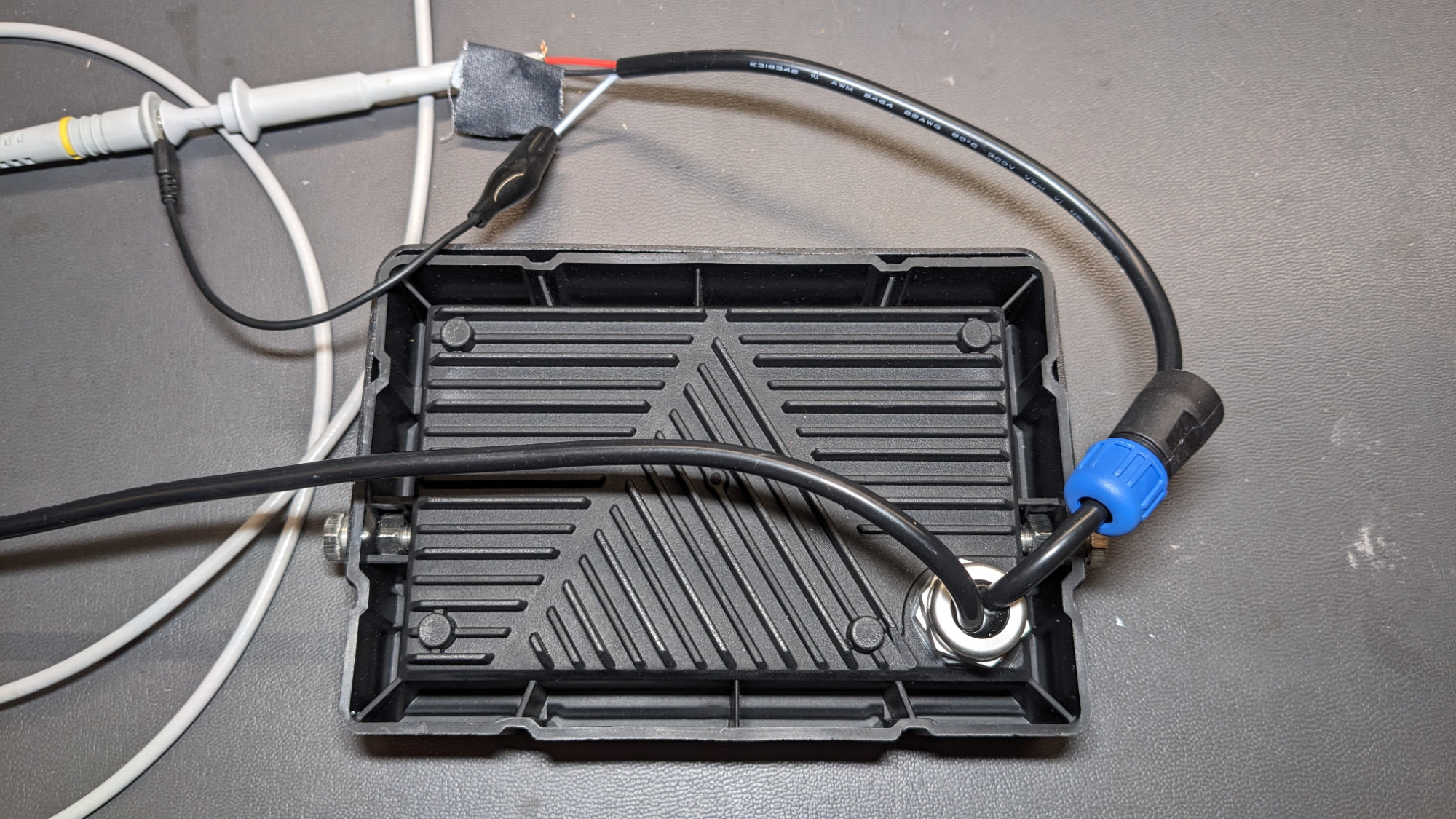
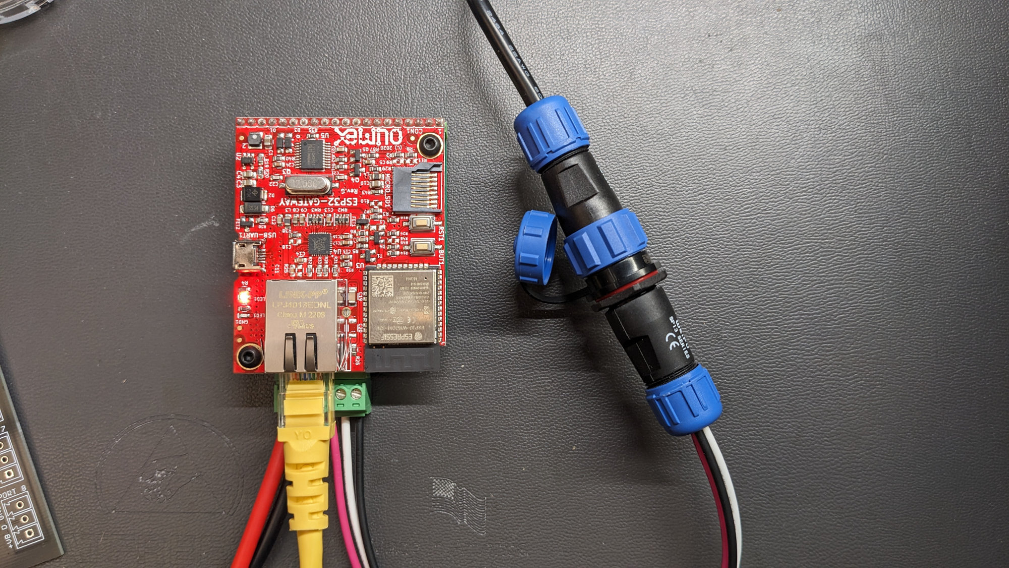
Probing the data output from the first light in the set. The left black wire is the power input from the power supply. The right black wire is the power and data output to the second light in the set. I’ve replaced the second light with an oscilloscope probe. I also slipped the backshell for a waterproof connector over the wire so I don’t forget later.
At this point, I cut the power supply and first light from the rest of the set. I removed the outer jacket from the cable to the second light and stripped the wires. I used a DMM to verify the black wire was 48 VDC and the white wire was ground as shown in the FCC filings.
Then, before I forgot, I slipped a waterproof connector’s backshell over the power and data output cable since I’m going to put a set of connectors between the first and second lights. This will let me easily swap between using the controller built into the first light and my WLED controller later.
To decode the protocol, I connected an oscilloscope probe to the red data wire and white ground wire as shown in the photo above. I then observed the protocol’s waveforms while using the set’s native app to set the lights to various colors.
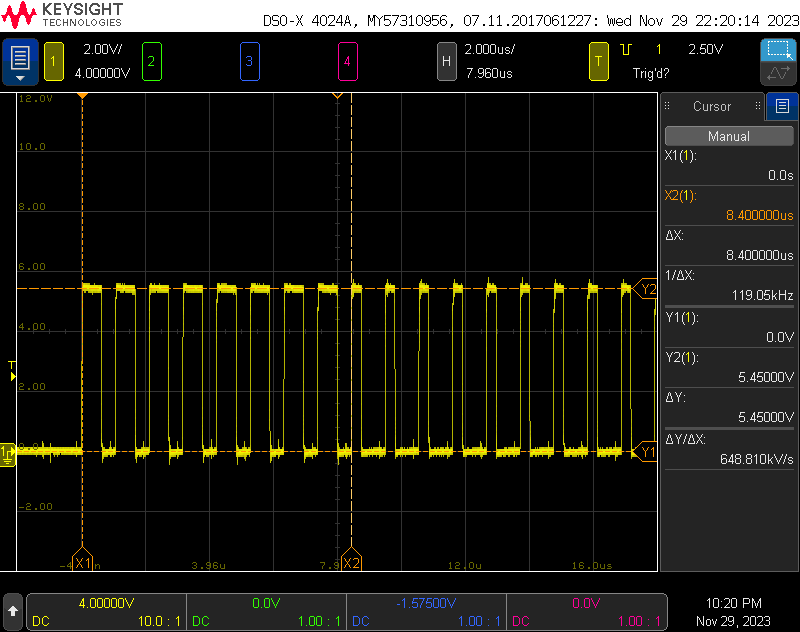
The first 17 bits of the protocol.
The waveform was the WS2811 protocol at 950 kHz and using 5 V logic levels. Each light had 4 channels of color information and each channel had 8 bits. The transmission order was { 8 bits of warm white, 8 bits of red, 8 bits of green, and 8 bits of blue }.
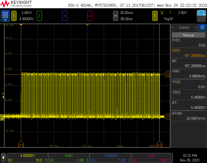
B
The total length of the data sent to the lights was ~167.2 μs. At 950 kHz, this is 160 bits which corresponds to 5 lights of 4 channels of 8 bits.
New 48 V WLED Controller
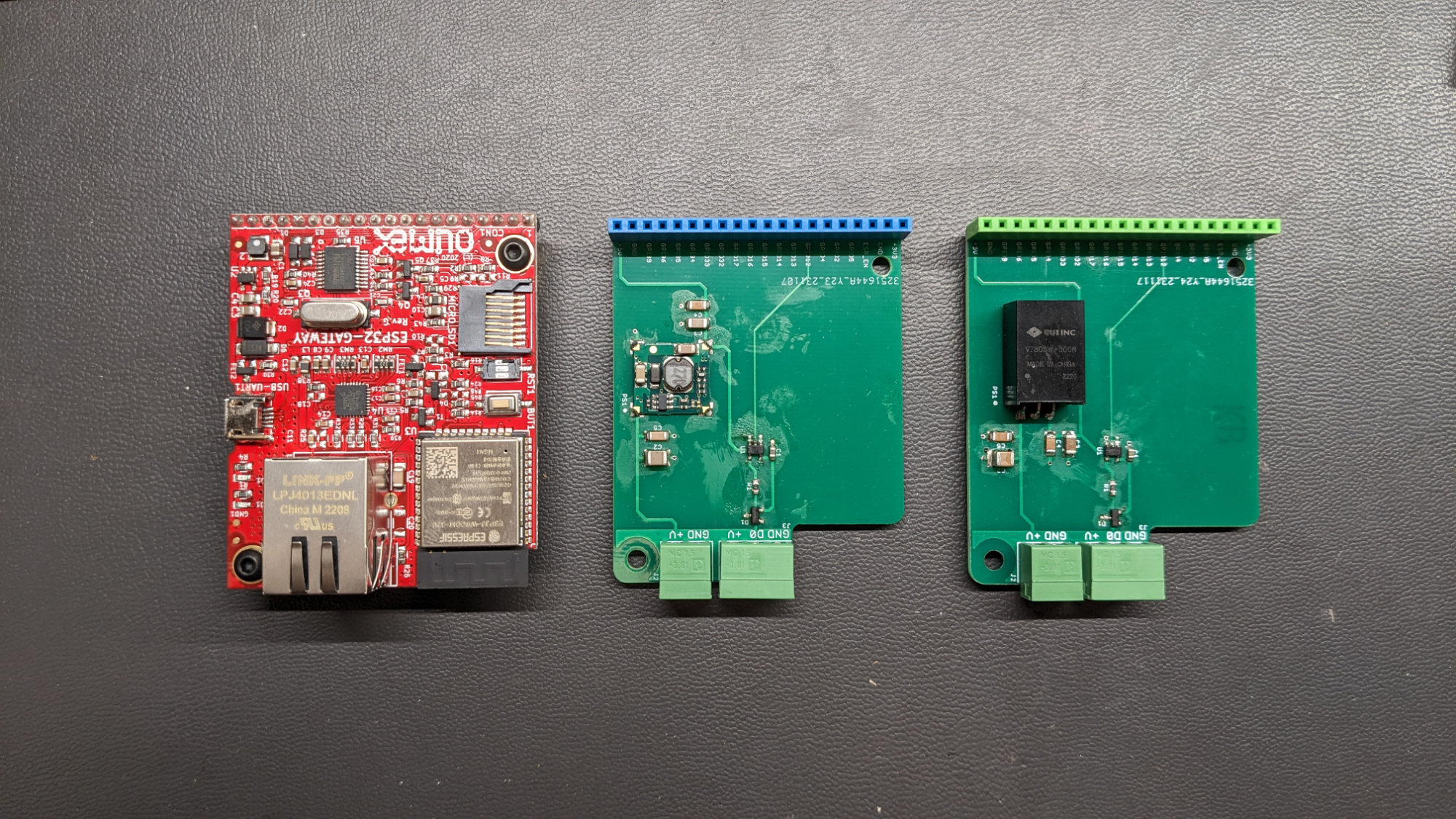
Left to right: the Olimex ESP32 Gateway board that will run WLED, my first interface board with a maximum supported pixel voltage of 24 V, and my new interface board with a maximum supported pixel voltage of 48 V.
With the pinout and protocol known, it was time to look at controlling the lights with WLED, an Olimex ESP32 Gateway, and my interface board. The interface board I built previously has a 5 V DC/DC converter to power the Olimex ESP32 Gateway board from the LED power supply. The DC/DC converter is rated up to an input voltage of 36 V.
Since these lights are 48 V, I had to redesign the interface board with a DC/DC converter rated up to an input voltage of 72 V and upgrade the input capacitors to some with a 100 V rating. The Olimex ESP32 Gateway board, the 24 V version of the interface board, and the 48 V version of the interface board are shown in the photo above.
The WLED controller connected to the second light in the string. I placed a 3-pin male waterproof connector on the light’s power/data input cable. This is connected to a 3-pin female waterproof connector with a short pigtail to the WLED controller.
I soldered a waterproof 3-pin male connector on to the power and data cable to the first light in the string of now five lights. I used a short pigtail with a mating female connector to connect the string of lights to the WLED controller and interface board. I also soldered a female connector on the power and data output of the light with the wireless module inside it. The connectors allow me to swap easily between using 6 lights with the factory controller or 5 lights with the WLED controller.
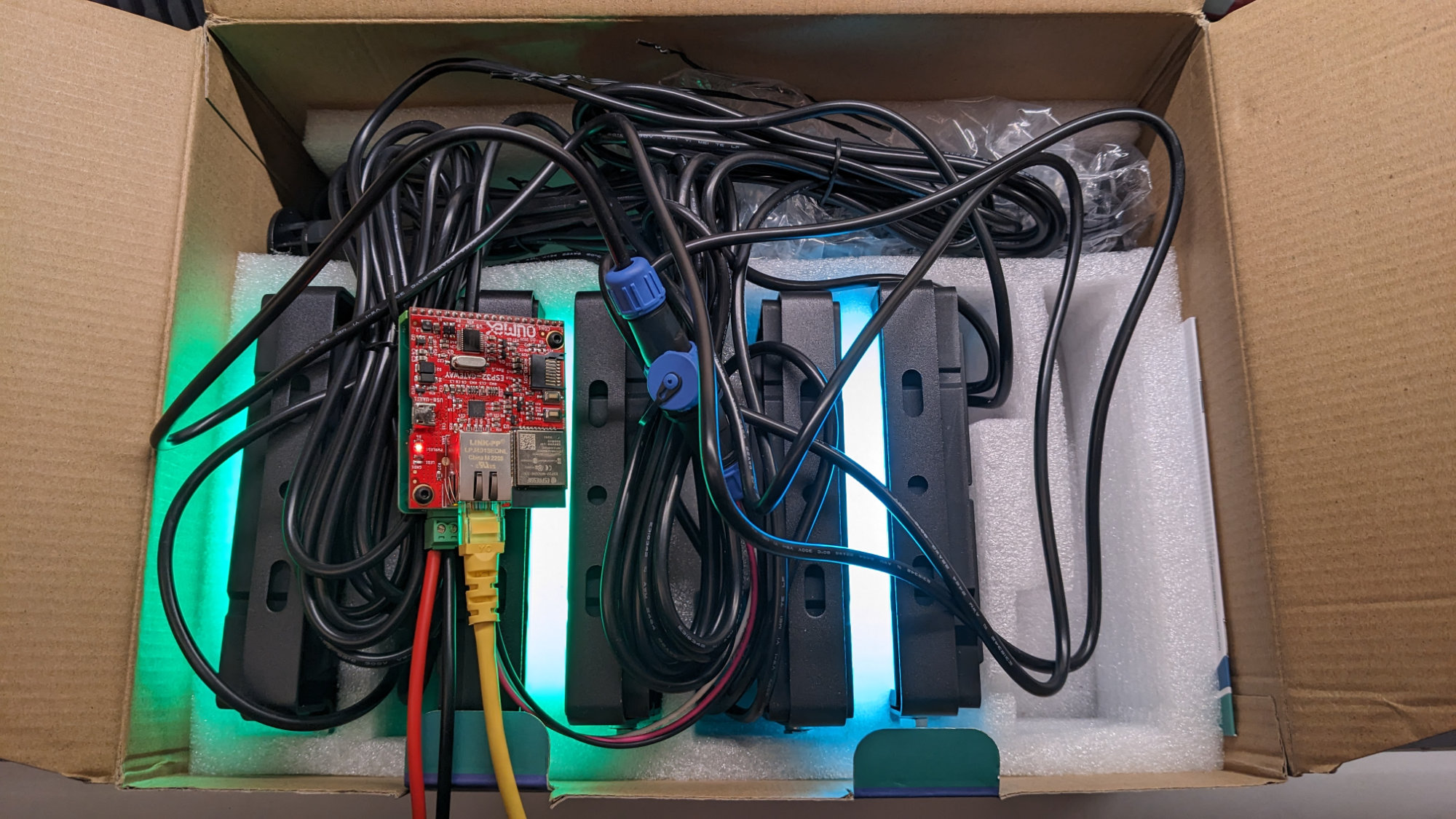
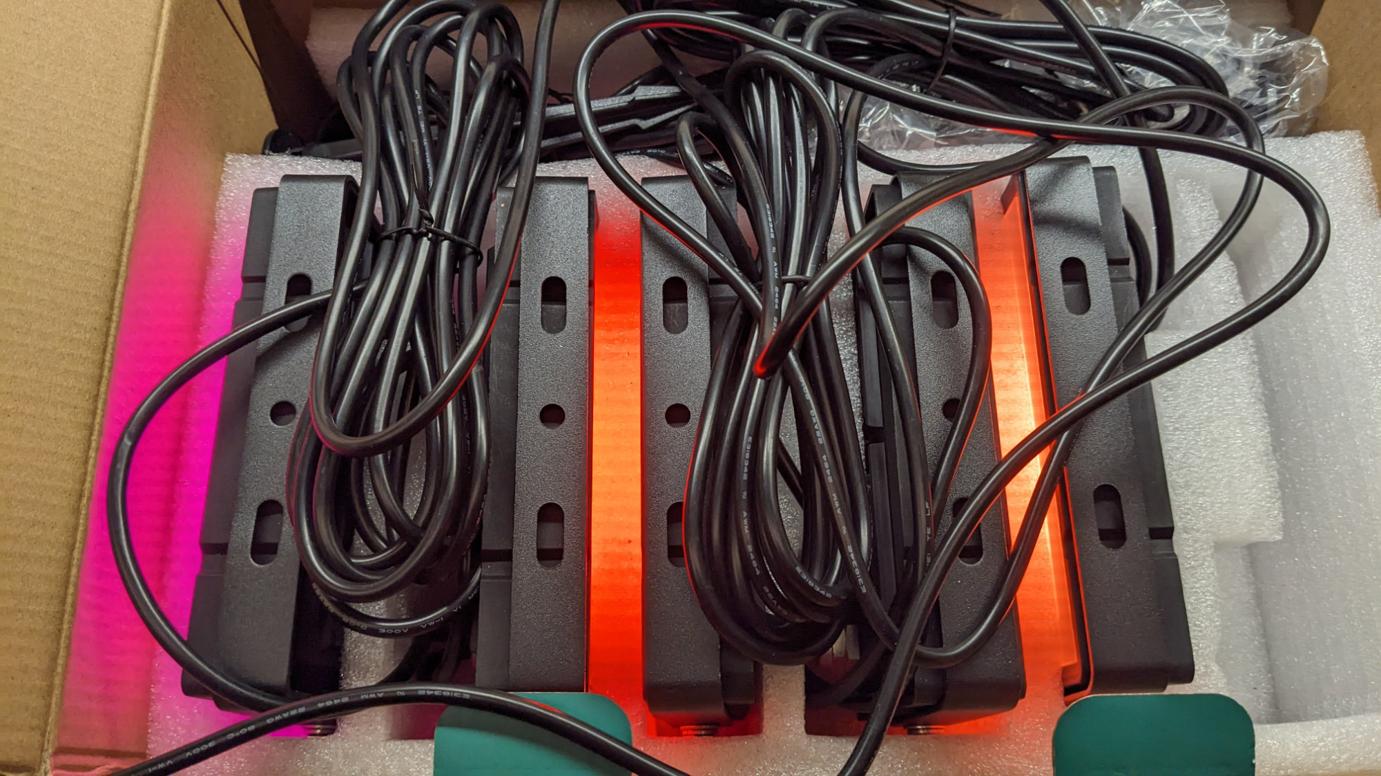
Power from my bench supply, an Ethernet cable, and the last five lights of the string are connected to the WLED controller. I didn’t feel like dealing with the 15 meters of cables so I did my initial testing at lower output levels in the box. There’s a fire extinguisher under my desk too.
With everything connected, it was time to try out WLED with the lights. I threw everything in the box then threw the box on my workbench and powered up the controller and lights. The photo above shows the five lights, the connectors, and the WLED controller with the 48 V interface board.
More colors. Also still in the box.
While WLED supports RGBW pixels, permits reordering the color components, and swapping one color channel and with the white channel, it does not permit arbitrary reordering of the channel components. With this limitation, none of the WLED built-in effects work as expected. The best I could do with WLED is to select SK6812 RGBW pixels in the LED settings panel and multi RGBW in the sync interfaces panel. With these settings selected, WLED functioned as a transparent E1.31/ArtNet/DDP interface to the pixels.
Conclusions
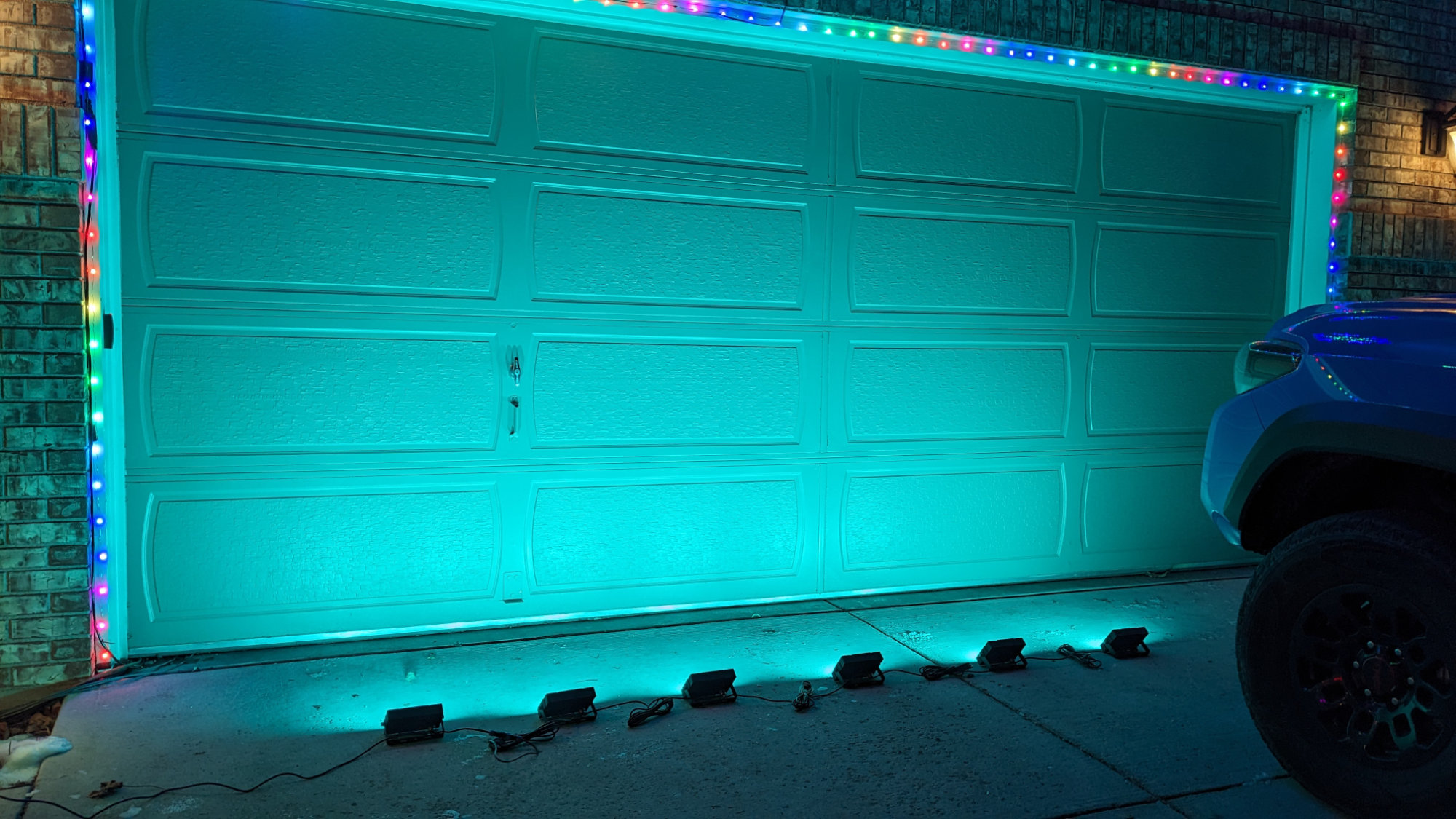
Hey! That’s 6 lights! Yep, I didn’t want to drag my bench supply outside and I don’t have the connectors I want for the 48 V power input yet so this photo is taken using six lights and the stock controller built into the first light.
These floodlights are available in both a 40 W set and at 100 W set. Both sets function similarly with a power supply, a wireless controller built into the first light, and then five more daisy chained lights that are controlled by the first light. The 40 W set uses a 24 V power supply and the 100 W set uses as 48 V power supply.
As long as you’re willing to use only five of the six lights from the set, have a controller supporting the set’s supply voltage, and can live without using most of the built-in effects, either of these light sets can be used with WLED. Since WLED does not support arbitrary channel reordering, the built-in effects are nearly useless but the lights can still be controlled over the network.
Disclaimer: Glen may earn compensation for sales from links on this post through affiliate programs.