

Rinsing the bike off after a muddy night ride can be needed. Being able to see what you’re doing without getting your phone out or going inside the house is great.
Ever want to control some outdoor lighting without using your phone or going back in the house? Read on to see how I installed a set of landscape lights then built a set of outdoor, waterproof Zigbee buttons to control them using an nRF52840 module, Zigbee2MQTT, Python, and TinyTuya.
Disclaimer: Glen may earn compensation for sales from links on this post through affiliate programs.
Motivation

Behold my muddy butt!
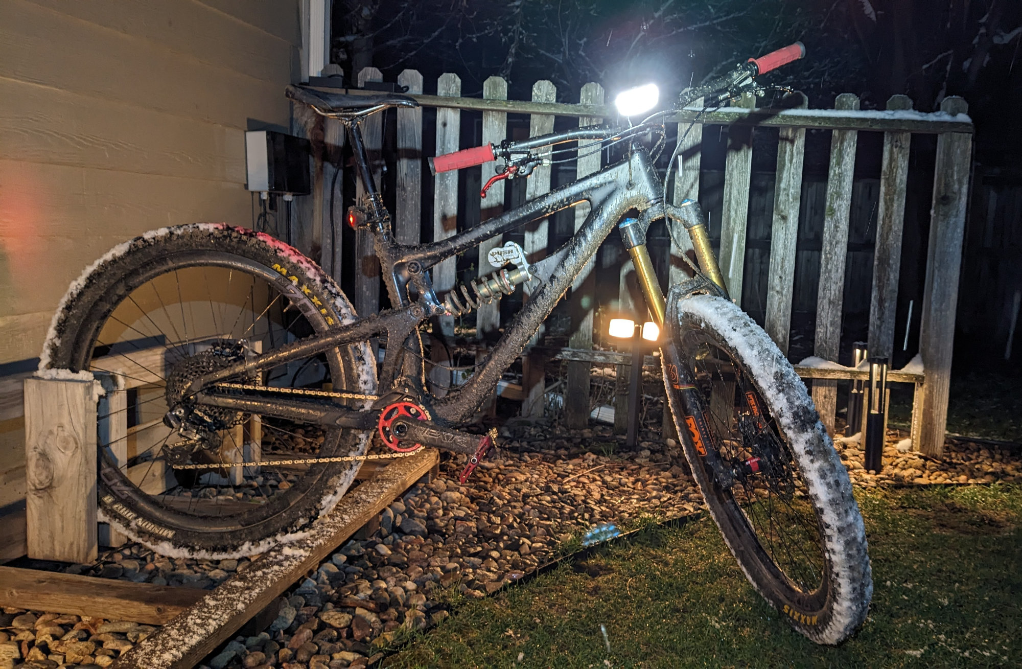
We had a much wetter than normal summer here last year. My bike (and myself) were often too muddy to bring in the house after a ride. I’d either get done with a night ride or get home after dark after a long drive home and couldn’t see to rinse the bike off in the backyard bike rack I built many years ago. I decided I needed some lights for the bike rack and I wanted to control them outdoors with real buttons. I did not want to need to dig my phone out of my pocket or take my gloves off or walk in the house to control the lights.
The Lights
Thank you, XMCOSY+, for the free set of lights!
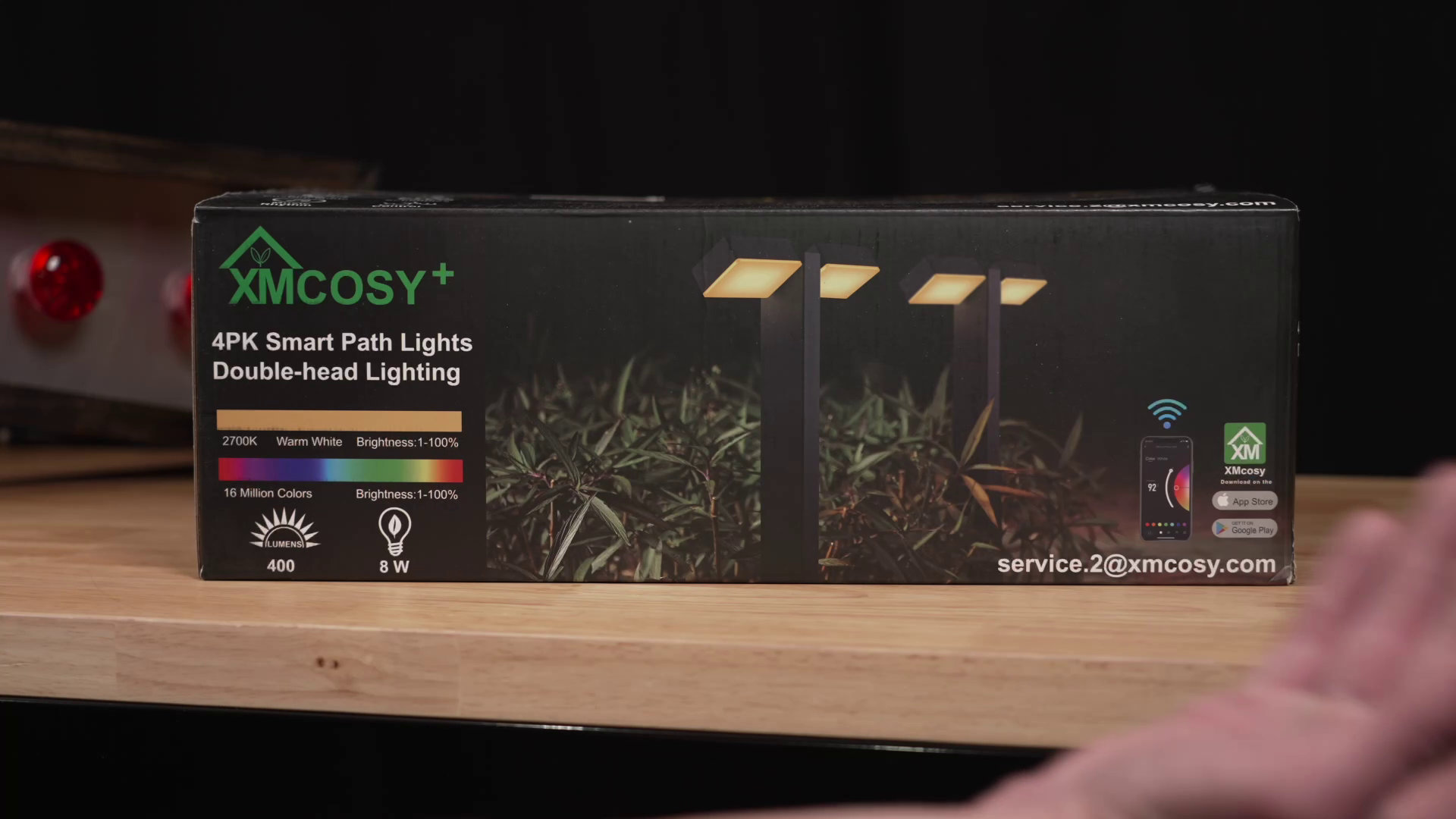
After writing about the XMCOSY+ string lights I hung in my backyard, XMCOSY+ offered to send me a set of their Low-Voltage Double-Head RGBW Pathway Lights for free. I took them up on the offer.
The lights feature warm white and red, green, and blue LEDs. They can be set to warm white or any color using the Tuya Smart Life app for iPhone or Android. Each light has two heads that can be swiveled up and down independently to direct light where it’s needed. These lights are usually aimed downward to light up a path or walkway but they can be pointed upward to light up plants or wash walls too.
Behold my muddy bike!
They were likely expecting a more traditional unboxing and review video but I put the lights to use lighting up the bike rack in my backyard. They really do make it easier to see to rinse off the bike. You can see one of the lights behind my snow and mud covered bike in the photo above.
The Light Set
The complete XMCOSY+ dual-headed pathway light set.
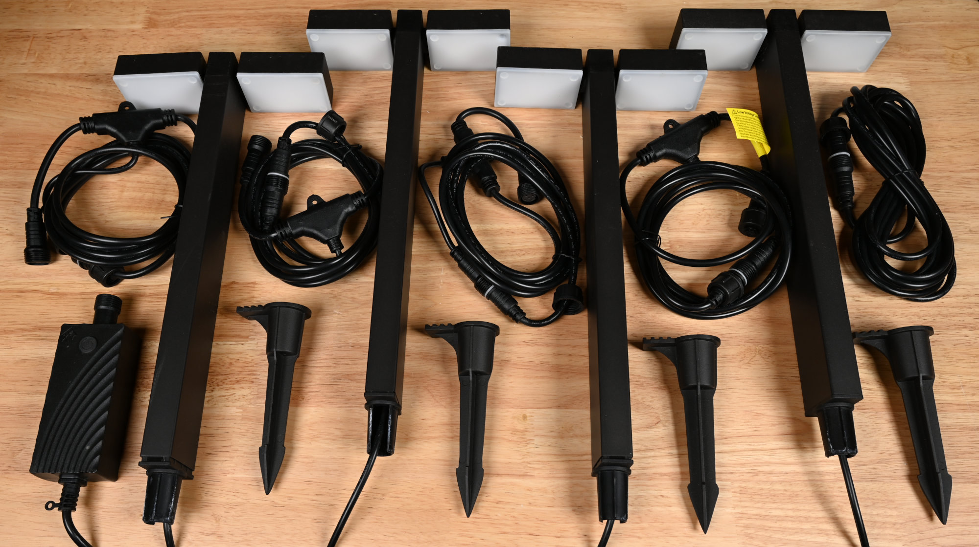
The light set includes a power supply, four 8-foot splitter cables, four ground stakes, four double-head pathway lights, and an extra 13-foot extension cable that can be used if the distance between the power supply and the first light or any two lights is greater than eight feet. A beefier 100 W power supply and extra extension cables are available separately as well.
Power Supply Details
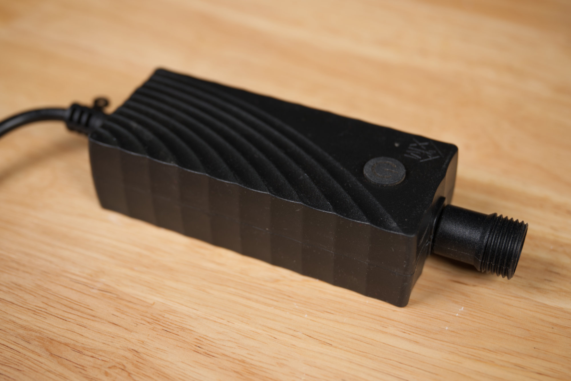
The 36 W power supply for the lights. The power supply includes both a 12 V, 3 A switching power supply and a Tuya cloud-based Wi-Fi PWM LED controller.
The power supply is shown in the photo above. The AC line cord is on the left and the 5-pin female connector for the lights is on the right. The power supply is rated for 12 V at 3 A or 36 W and has both FCC and ETL certifications.
The power supply contains an embedded Tuya IoT Wi-Fi LED controller. The power supply’s connector has a +12 V common output and four ground returns for the four different colors of LEDs embedded in the light heads. Since all the lights are connected in parallel to the same output, the lights cannot be set to different colors at the same time.
Power Cable Details
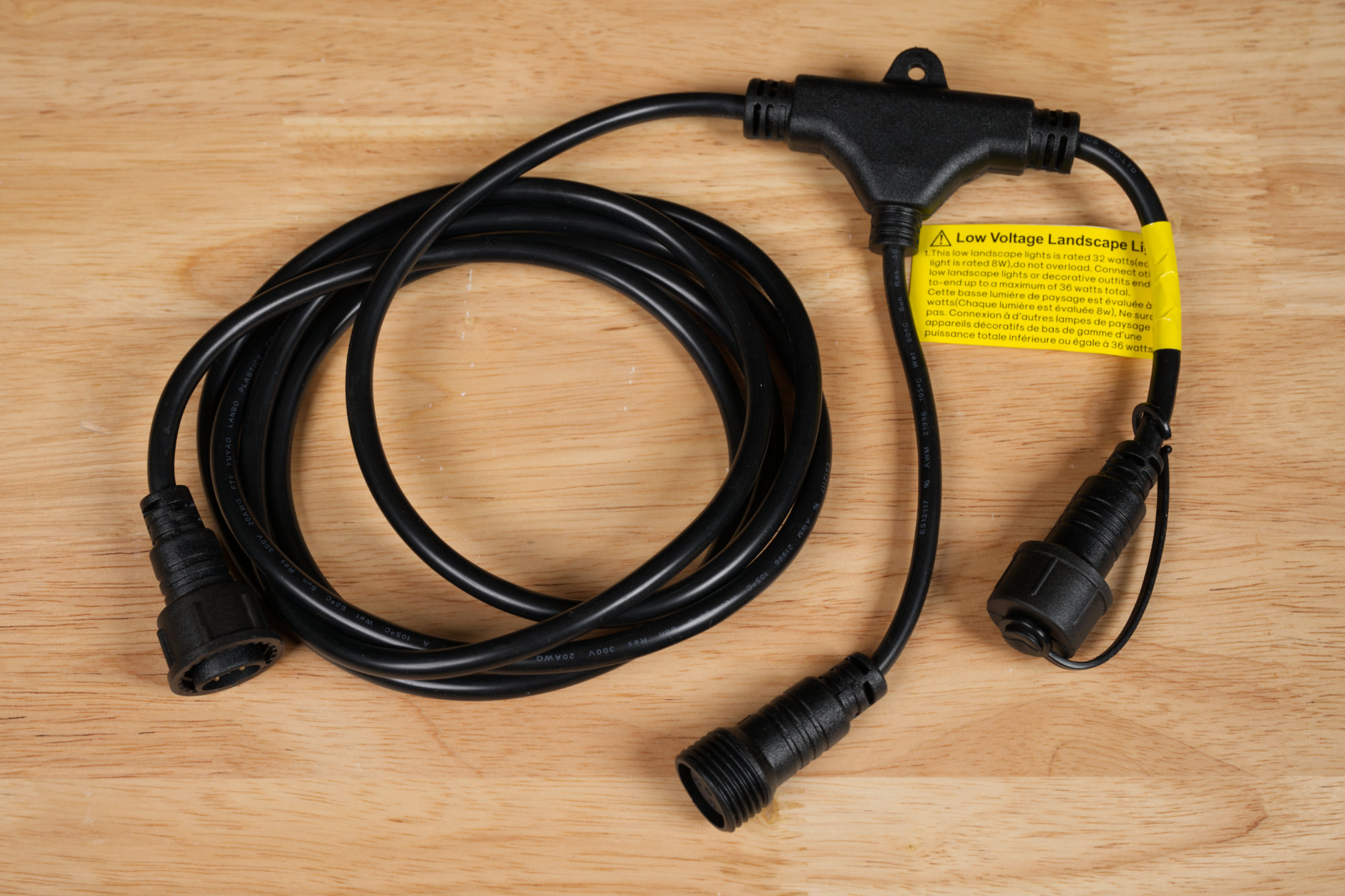
Eight foot, five pin splitter cable with one male plug and two female receptacles.
The lights include four 8-foot splitter cables and one 13-foot extension cable. One of the four splitter cables is shown above. The splitter cable has one male plug and two female receptacles. The male plug connects to the power supply or a previous splitter cable. The two female connectors connect to a light head and the next splitter cable. This is the normal cable that is strung between the power supply and the first light and then between each subsequent pair of lights.
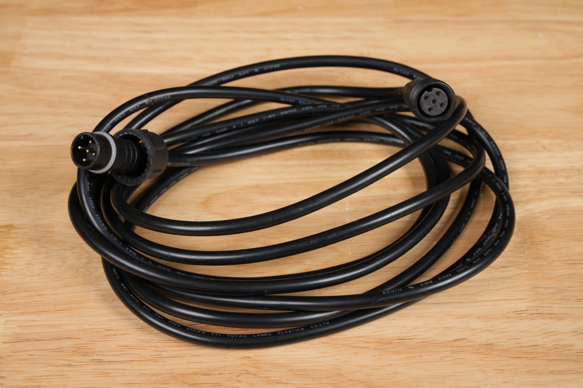
The 13-foot extension cable.
The light set also includes a single 13-foot extension cable. This cable can be put between the power supply and the first light or between any pair of lights if the distance between them is longer than that allowed by the 8-foot splitter cable. Extra extension cables can be purchased separately if needed. All the cables and connectors have five conductors.
Fixture Details
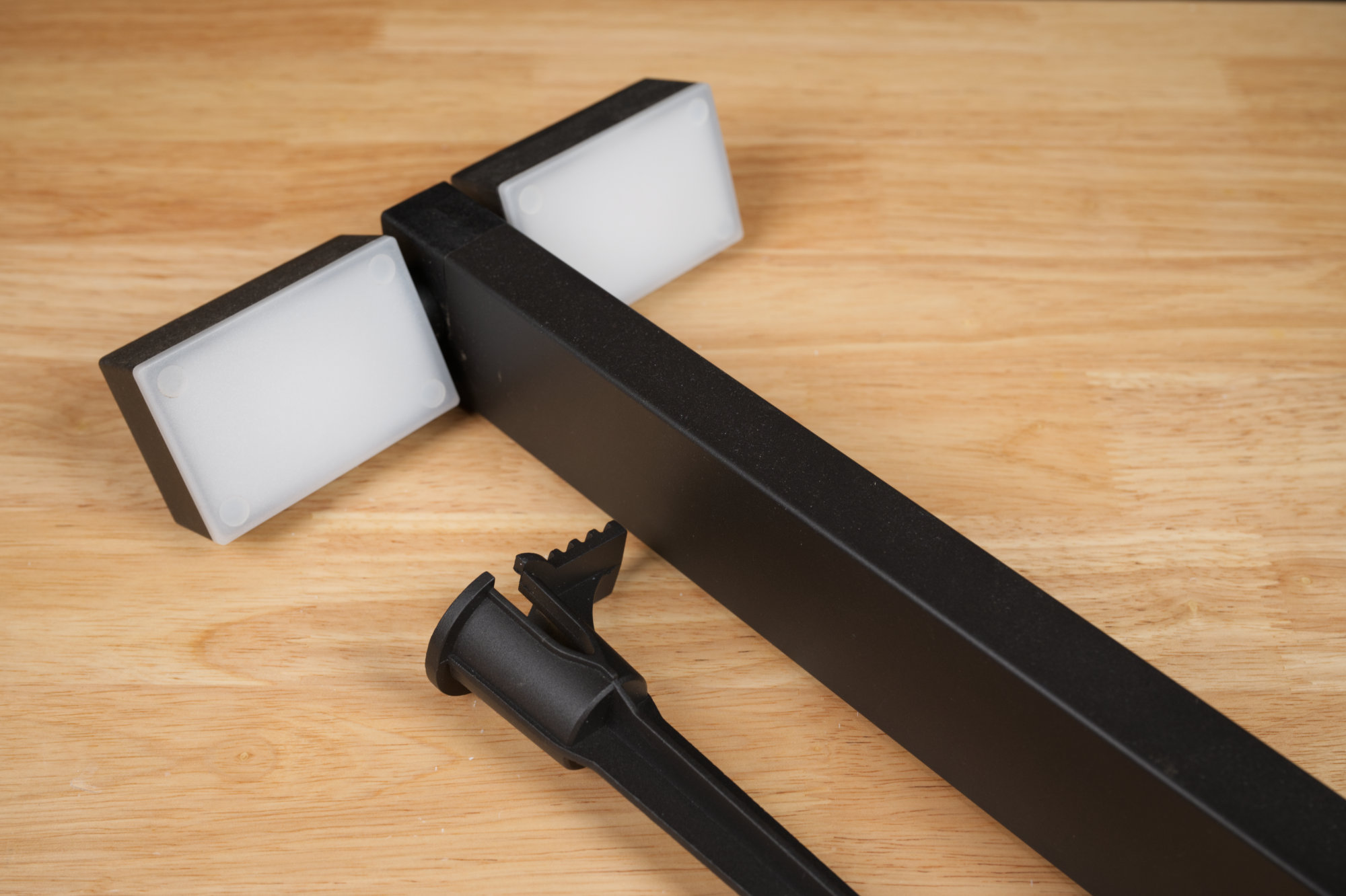
The pathway light and its metal ground stake.
Each light has two rotatable heads and a metal ground stake. To set up a light, use a rubber mallet to set the stake in the ground, press the lamp into the cup on the stake, and connect the light’s power connector to one of the female sockets on the splitter or extension cables.
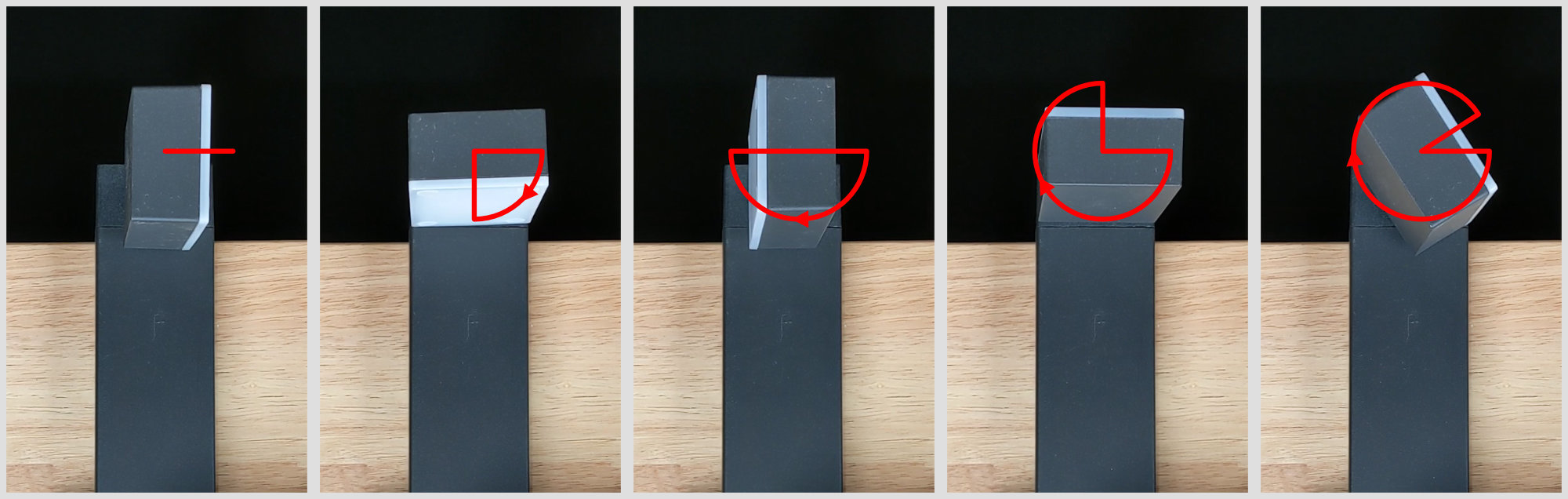
Each light head rotates independently through about 330 degrees.
Once the lamp is in place, the heads on either side of the post can be rotated independently to direct light where it’s needed. The total rotation is about 330 degrees.
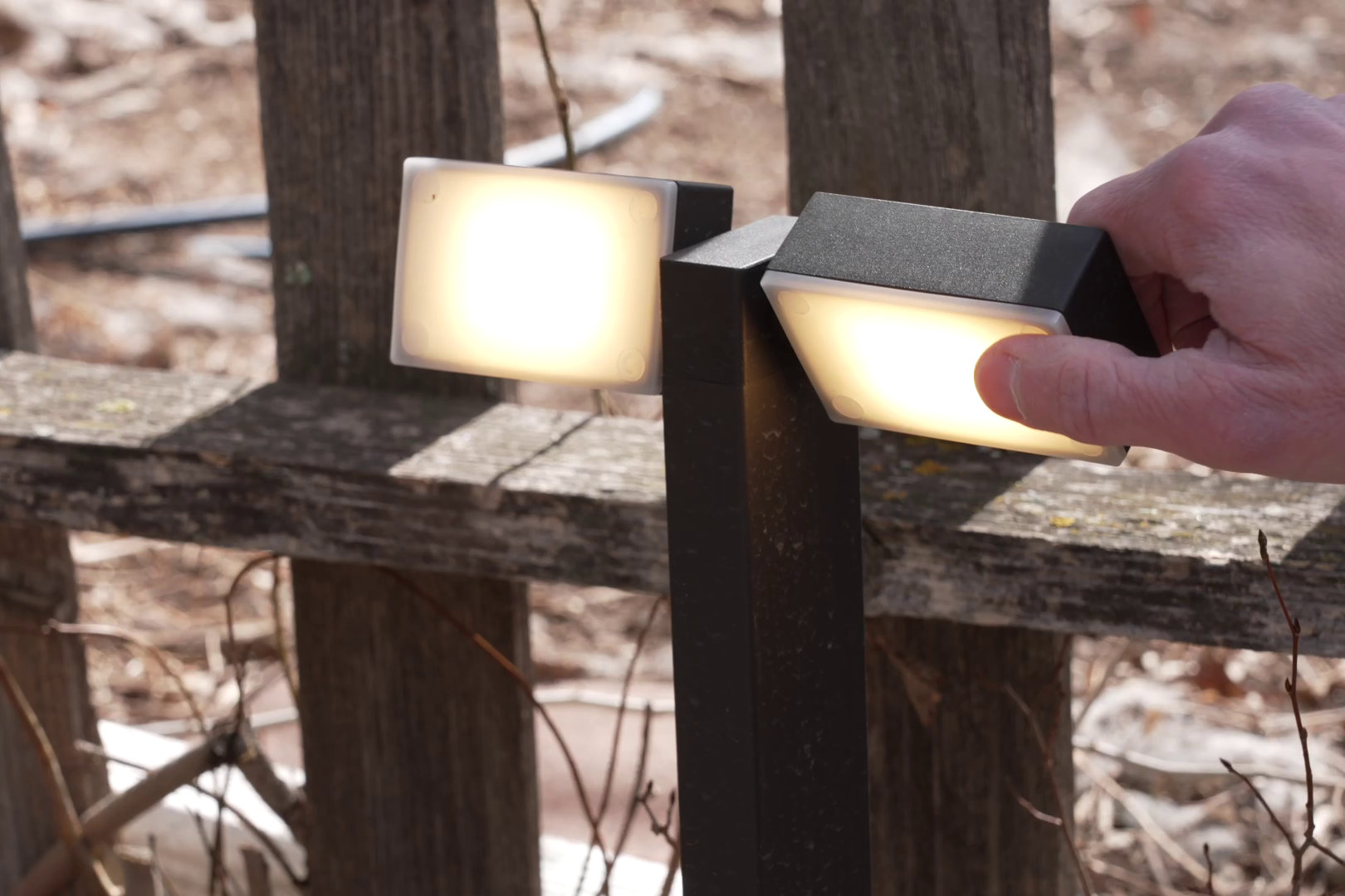
The two heads on each light can be rotated individually through an angle of about 330 degrees.
Most people will place the lights along a walk way and aim the lights down toward the walk way or will place them on the edge of a flower bed and rotate them out or down toward the plants. I placed one on either side of my bike rack and rotated the lights up toward the bikes.
Electrical Details
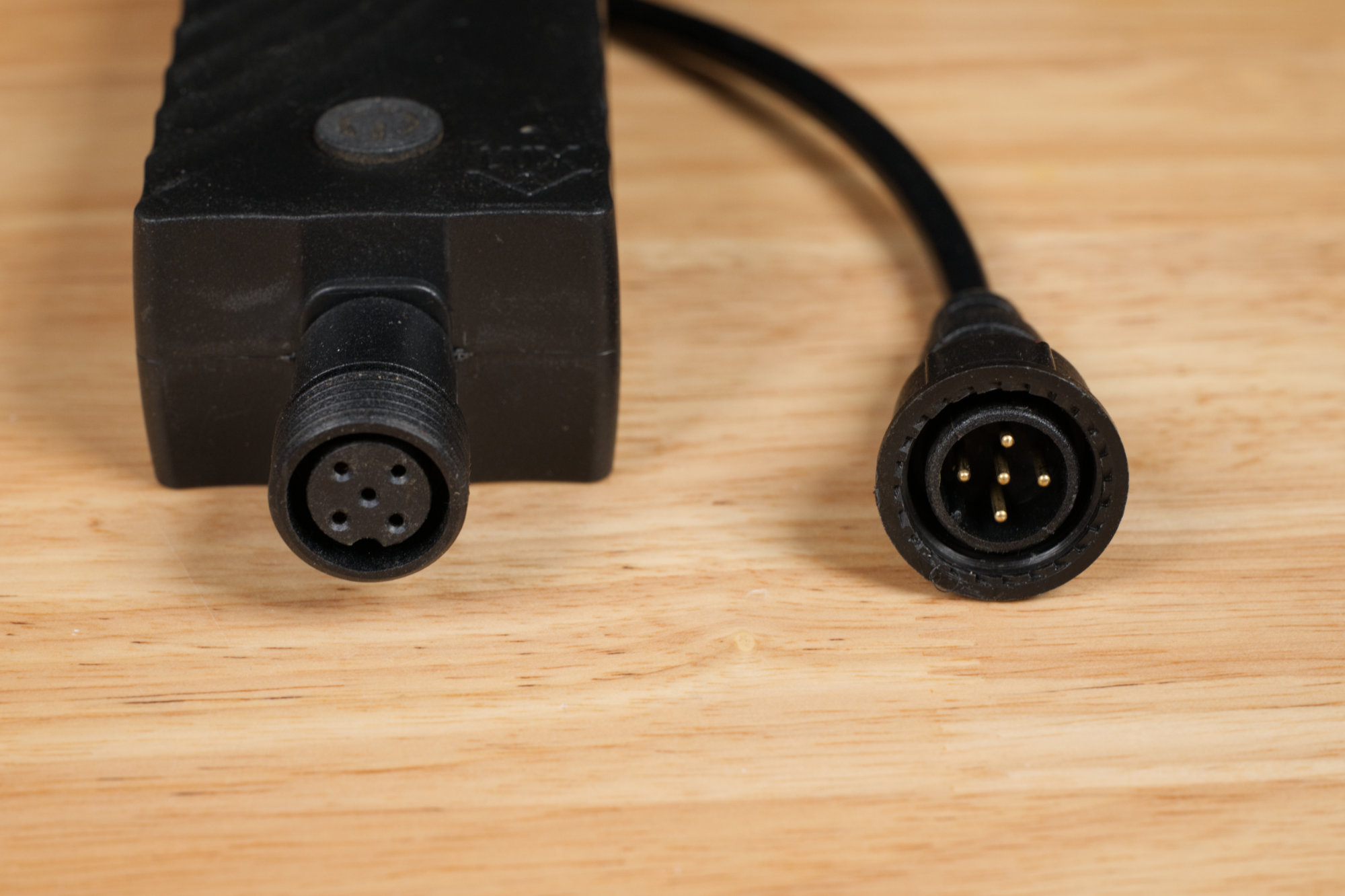
The female power supply connector and a male light head connector.
The power supply and lights use the proprietary five-pin connectors shown in the photo above. The connectors are about an inch in diameter.
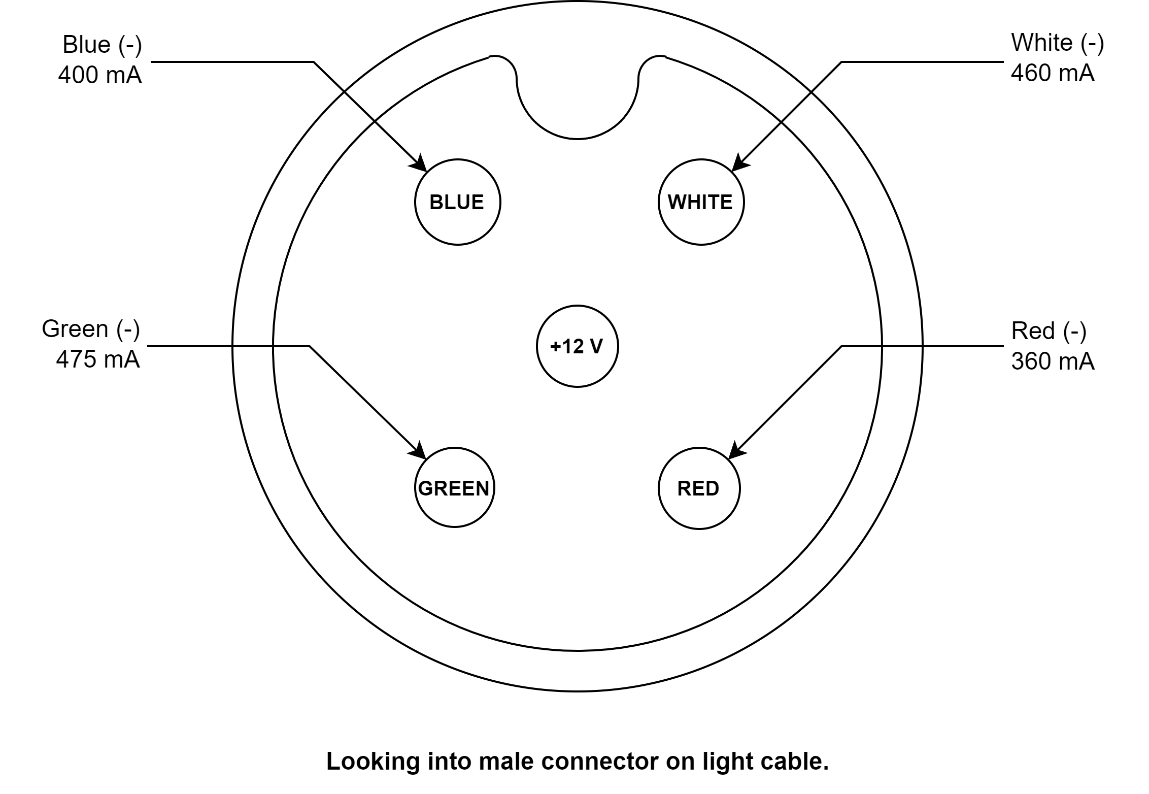
Pin out of the five pin connector looking into one of the male connector on one of the lights. The current values are for a single dual-headed light fixture.
This is the first light set I’ve examined that uses PWM dimming directly from the power supply / controller versus all the other sets that used some form of the WS2811 protocol.
Color Temperature
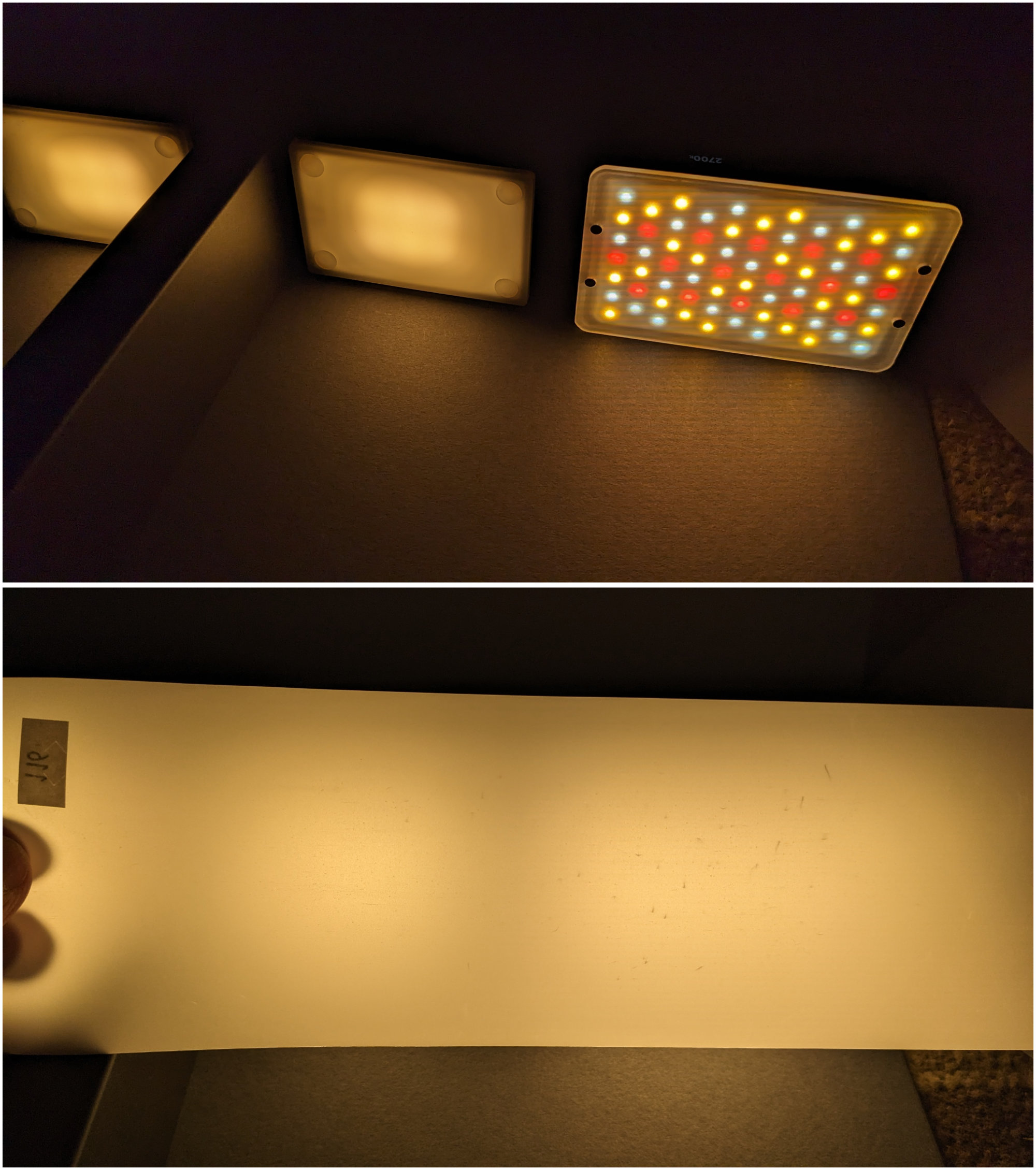
Top: one of the double-headed pathway lights next to my Aperture MC Pro video light. Bottom: holding a diffusion gel sheet in front of the lights.
I don’t have a spectrometer to measure the color temperature of the lights but I estimated the color temperature to be about 2700K by matching the color of an adjustable color temperature video light to the color of the pathway lights. Matching the color temperature was made easier by viewing both lights through a small scrap of diffusion gel. This matches with the lights claimed color temperature.
Controlling the Lights
Tuya Smart Life App
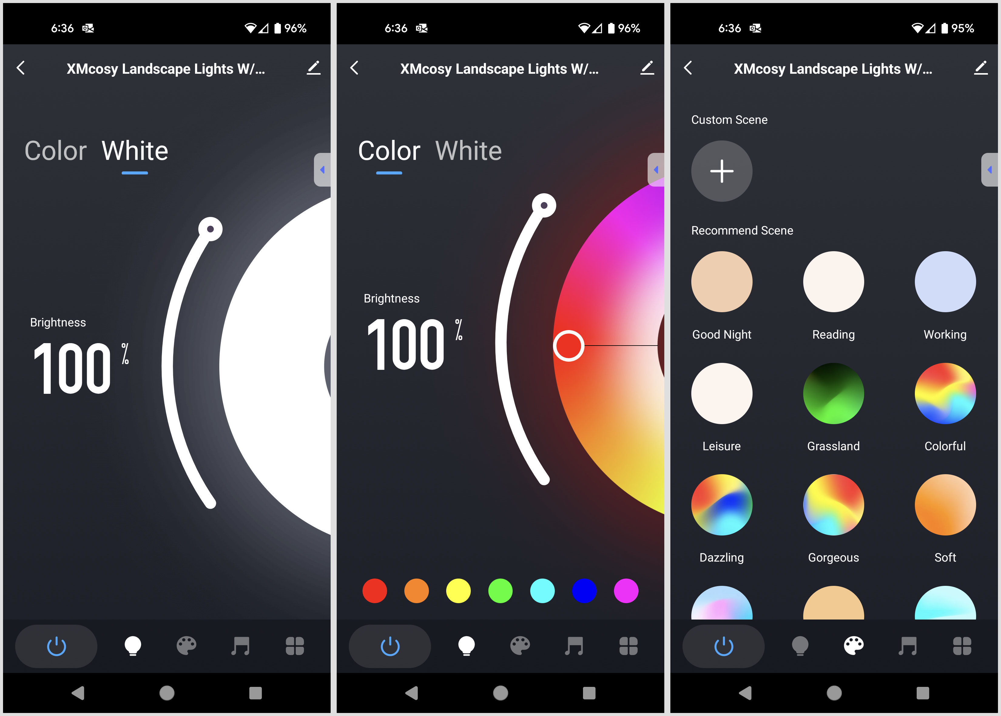
Three screens from the Tuya Smart Life App used to control the pathway lights.
These string lights are based on a Tuya IoT processor and as such can be controlled via the Tuya Smart Life app. Three screens from the app are shown in the image above. The leftmost screen shows the slider used to adjust the brightness of the lights when they are set to white. The middle screen shows the color wheel and slider used to adjust the color and brightness of the lights when they’re set to color. The rightmost screen shows some of the color changing effects these lights can do. Note that all lights are always the same color.
All in all, I think the app is adequate for most people’s needs. I, however, intend to control these lights using the TinyTuya library from a Python script in conjunction with the Zigbee buttons I’m building.
TinyTuya
Describing how to get started with TinyTuya is beyond the scope of this blog post. Fortunately, the documentation and getting started guide for the library is quite good and the examples and issues pages cover most of the missing details.
The Python script below shows the basics of turning these lights on, setting them to white at full brightness, and turning them off again.
import tinytuya
import time

ttdevs={}
ttdevs['bike_stand_floods'] = ("<DEVICE ID>", "<DEVICE IP>", "LOCAL KEY")

#----------------------------------------------------------------------------------------------
# turn tuya floods on or off
#

def tuya_floods (name, on):
  print ("sending " + ("on" if (on) else "off") + " request to " + name + "...")

  d = tinytuya.BulbDevice(ttdevs[name][0], ttdevs[name][1], ttdevs[name][2])
  d.set_version(3.3)
  d.set_socketPersistent(False)

  if on:
    d.turn_on()
    d.set_white()
  else:
    d.turn_off()

  print (("on" if (on) else "off") + " request to " + name + " done.")

#----------------------------------------------------------------------------------------------
# main
#

if __name__ == "__main__":

  while True:
    tuya_floods ('bike_stand_floods', True)
    time.sleep (1)
    tuya_floods ('bike_stand_floods', False)
    time.sleep (1)
Cloud-Free Alternatives
In addition to using the Tuya Smart Life app or the Tuya local API via TinyTuya, the lights can be controlled using common off-the-shelf PWM RGBW LED strip controllers such as those made by Gledopto, Zooz, and Shelly. A brief survey of some available 3rd party controls follows, but for now, I’m personally sticking with TinyTuya and the stock controller.
The easiest way to connect the lights to a 3rd party controller is to cut the male connector off the 13-foot extension, strip the wires, and connect the wires to the new controller. The female end of the extension may then be connected to a splitter cable or a pathway light as normal. The black wire in the extension cable is the common +12 V. The remaining wires are white, red, green, and blue and are the grounds for their respective colors of LEDs.
Gledopto 5-in-1 Zigbee Controller

The Gledopto Zigbee Pro+ 5 in 1 Smart LED Controller.
If you have an existing Zigbee network, my favorite Zigbee LED light controller is the Gledopto Zigbee Pro+ 5 in 1 LED controller #GL-C-201P. It can control single color, CCT white, RGB, RGBW, and RGBCCT LED strips or lights. The lever terminal strips are convenient and it’s compatible with Zigbee2MQTT out of the box.
To use this controller with the XMCOSY+ path lights, press the “Opt” button until the indicator LED is yellow to place the device in RGBW mode. Once in RGBW mode, add it to Zigbee2MQTT and it’ll show up as a GL-C-007P Pro RGBW controller. You can then set the device’s attributes to control the attached lights.
I purchased mine from AliExpress. Be sure to click “5in1 Pro Plus” before adding the device to the cart if you go this route. There are also similar looking devices on Amazon like the GIDEALED Smart ZigBee 3.0 LED Controller 5 in 1 but I haven’t personally tried these.
Zooz RGBW Z-Wave Controller
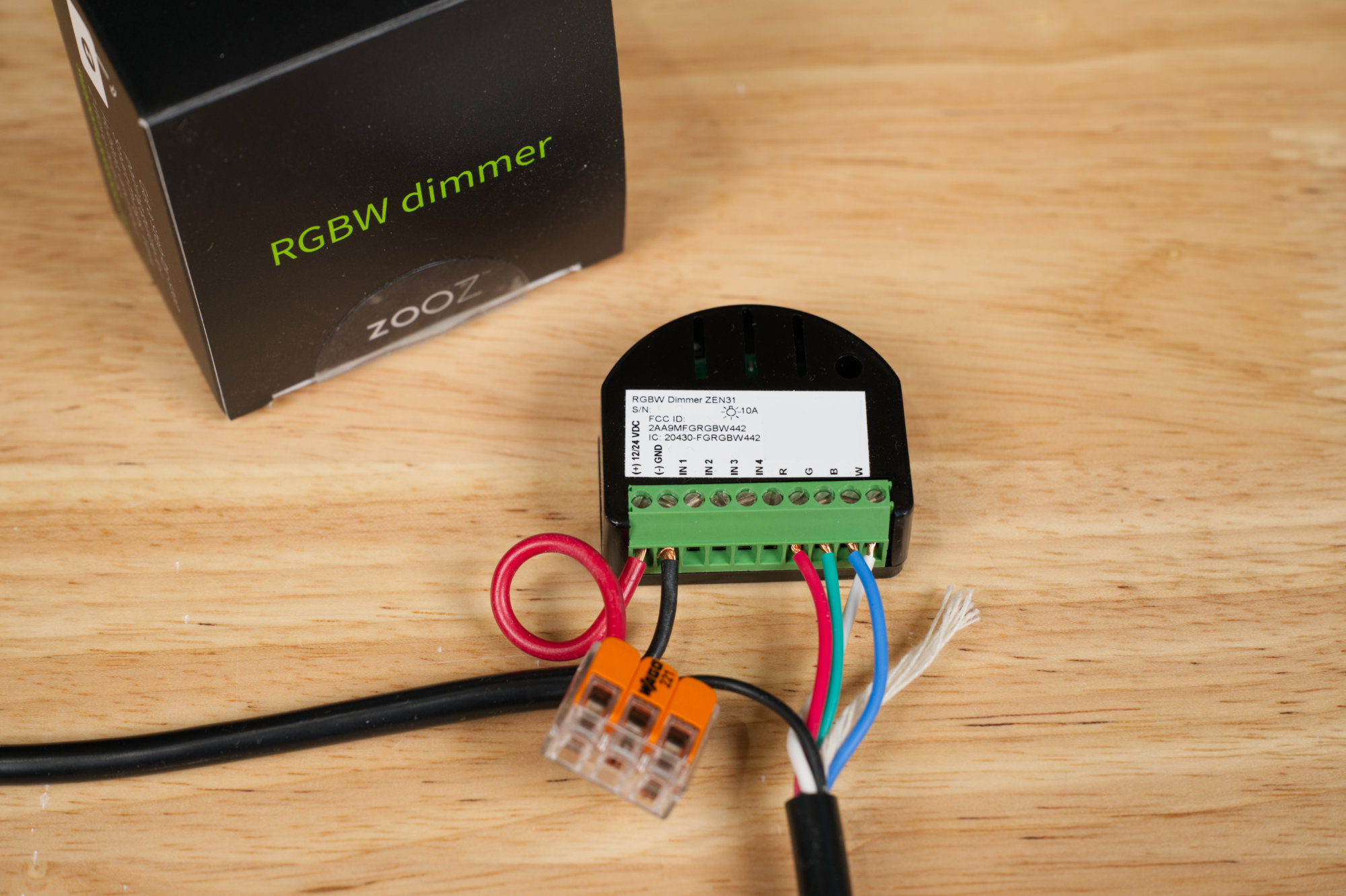
The Zooz ZEN31 RGBW Dimmer. The cable on the left is connected to a +12 V power supply. The cable on the right is the extension cable that came with the lights that I cut up and connected to the dimmer. If this were for anything other than testing, I’d do a neater job stripping and inserting the wires in the terminal strip.
If you have a Z-Wave network or are looking for a UL-certified LED controller, the Zooz ZEN31 RGBW dimmer is a great alternative to the Zigbee devices mentioned above. It can be monitored and controlled using an MQTT broker, the Z-Wave JS UI software, and a Z-Wave dongle like the Zooz Z-Wave Long Range 800 Stick. In the photo above, I have the Z-Wave RGBW dimmer connected to a power supply (cable from the left) and the cut extension cable that came in my set of lights (cable going down).
Shelly RGBW Wi-Fi Controller
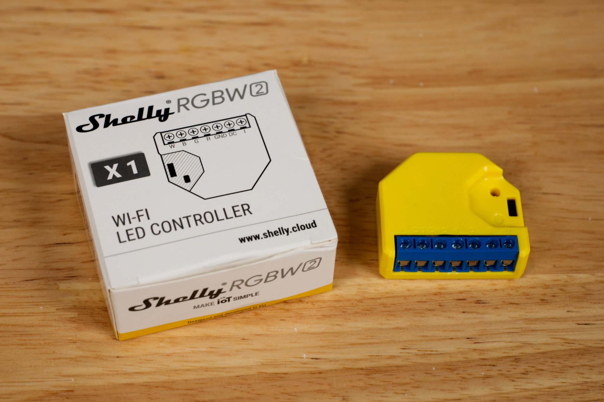
The Shelly RGBW2 Wi-Fi LED controller. It’s the only 3rd party controller that sits directly on a Wi-Fi network and thus doesn’t need a Zigbee or Z-Wave hub.
If you don’t have an existing Zigbee or Z-Wave network or want a simple Wi-Fi RGBW LED controller, the Shelly RGBW2 Wi-Fi LED controller is a great product. It can talk directly to an MQTT broker over your existing Wi-Fi network without the need for Zigbee or Z-Wave hub.
Outdoor Rated Controls
My goal for this project is to be able to control the lights without having to dig my phone out or take my gloves off. To do this, I want some physical buttons! And I want them to be waterproof so they can be located outdoors!
The Buttons
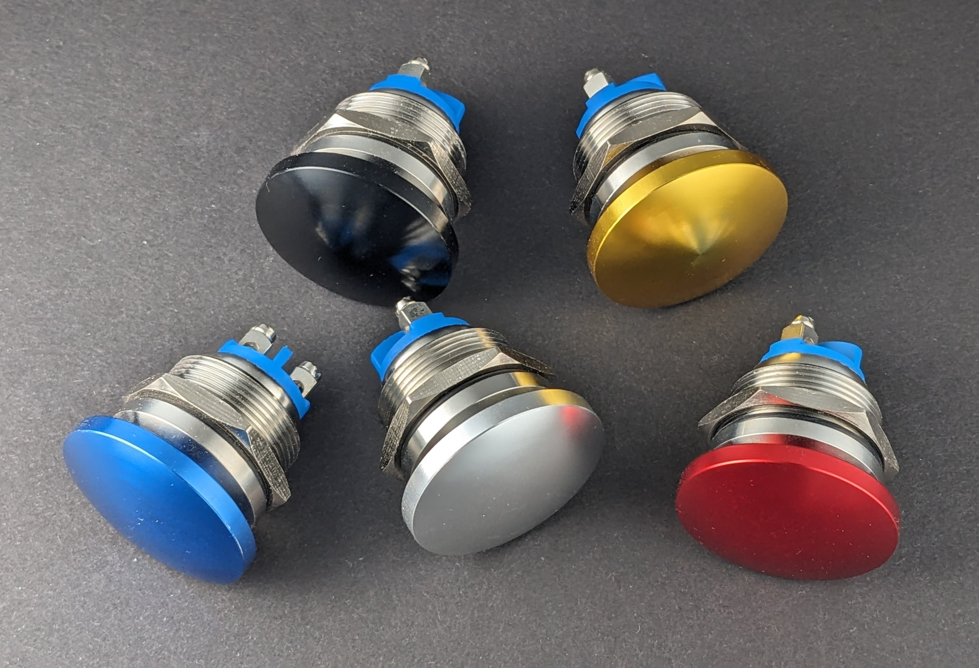
Generic 22 mm momentary mushroom head push button switches.
After digging through my boxes(!) of industrial controls and browsing Amazon and AliExpress, I selected some generic 22mm momentary mushroom head push buttons in bright colors. They’re listed as IP65 but I’m a bit skeptical. Time will tell. The buttons are available from Amazon under the Apiele brand name. I selected a green button to turn the lights on and a red button to turn the lights off.
The Enclosure
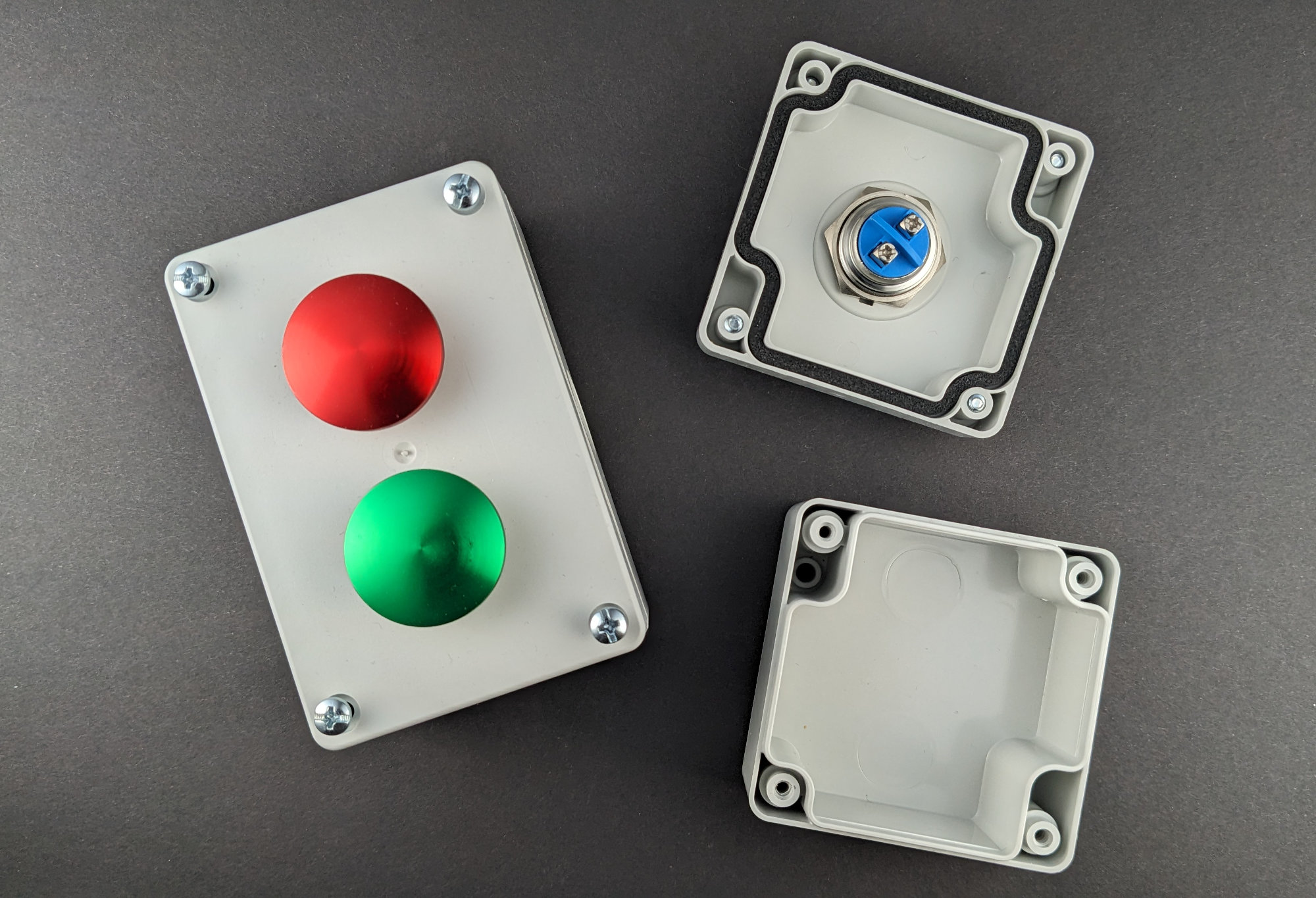
Automation Direct’s one-hole and two-hole waterproof button enclosures.
For an enclosure for the buttons, I used Automation Direct’s SA100SL single-hole and SA105-40SL double-hole waterproof pushbutton enclosures. These enclosures have pre-drilled 22 mm holes, are IP65 rated, and are relatively inexpensive. These enclosures also have plenty of room for a small circuit board and battery.
Existing Solutions
Indoor-Rated Zigbee and Wi-Fi Smart Buttons / Scene Controllers
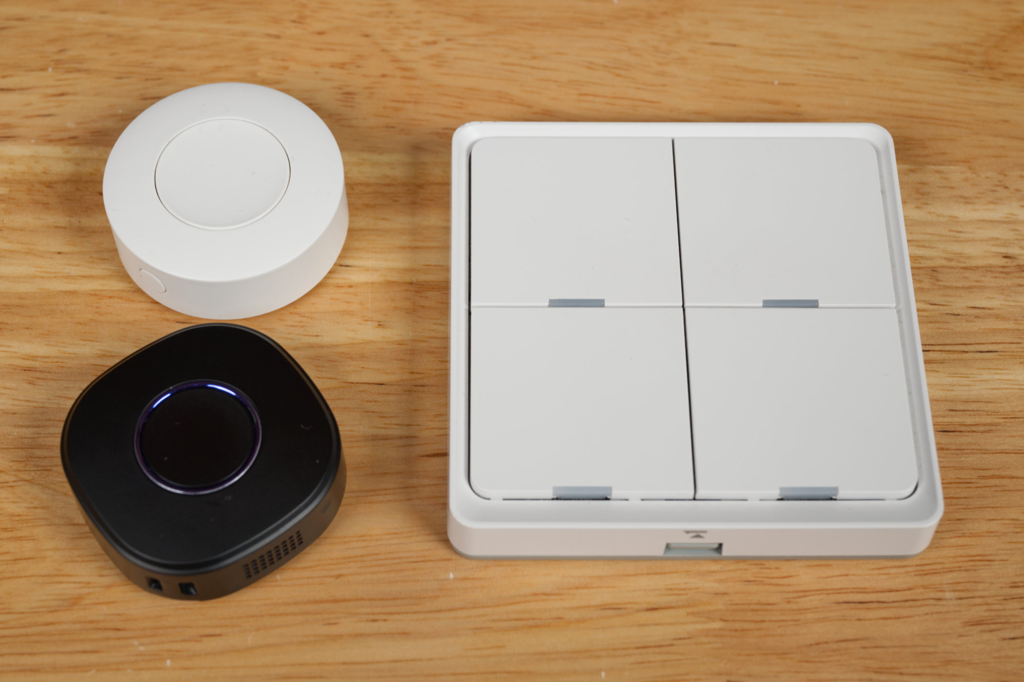
Upper left: Sonoff SNZB-01P Zigbee wireless switch. Lower left: Shelly Button 1 in black. Right: MOES Wireless Smart Scene Switch.
If you’re good with locating the buttons to control the lights indoors or in the garage, there are lots of Zigbee options and at least one Wi-Fi option. My favorite Zigbee buttons are the single-button Sonoff SNZB-01P Smart Button and the four-button MOES Wireless Smart Scene Switch. These directly integrate with Zigbee2MQTT and a Python script subscribed to their MQTT messages can be used to control other Zigbee, Z-Wave, and Wi-Fi devices on the network.
The only battery-powered Wi-Fi smart button I could find is the Shelly Button 1. Like other Wi-Fi devices, it does not require a Zigbee or Z-Wave hub to connect to the network. Like other Shelly devices, it can publish and subscribe to an MQTT broker directly.
The only downside to a battery-powered Wi-Fi button is it takes a few seconds to connect to the Wi-Fi network from its low-power sleep state before it can send the on or off command to the MQTT broker to send to any scripts or lights. This results in a very noticeable delay between pushing the button and the lights changing state.
The obvious solution at this point would be to rip the guts out of the Sonoff button, solder some wires across the button terminals, then connect the wires to the 22 mm pushbuttons and slap everything into the two-button enclosure. Oh wait, there’s only one button to solder wires to on the Sonoff device and the MOES device with multiple buttons is too big to fit in the waterproof enclosure.
Hue Light Switch Module
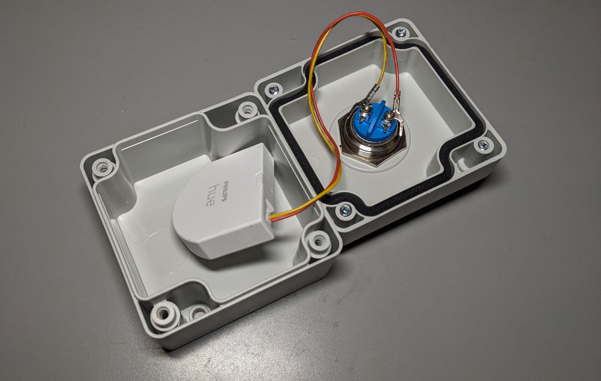
The Hue Wall Switch Module connected to a single button inside a single-hole waterproof enclosure.
After doing more searching, I stumbled on the Philips Hue Wall Switch Module. This device is almost perfect. It’s Zigbee and supports two buttons or two toggle switches. If you’re 100% in on the Hue ecosystem, this is the device for you. Connect it to some buttons or switches, add it to the Hue hub, create some automations to turn some Hue lights on and off and you’re done.
I’ve been trying to lessen my dependence on Hue devices, however, since they started requiring an account to use their app. Technically, the Hue Wall Switch Module is supposed to work with Zigbee2MQTT but I was experiencing high battery drain issues caused by the module sending attribute reports way too frequently. I did not experience these issues when using it with the Hue Hub.
If you want to get crafty, you can connect to the Hue Hub’s streaming API from a Python script, listen for the button pushes, and use those to trigger other devices outside the Hue ecosystem:
import requests
from requests.packages.urllib3.exceptions import InsecureRequestWarning
import json

HUE_HUB_URL_BASE    = 'https://<YOUR_HUB_IP>:443'
HUE_APPLICATION_KEY = '<YOUR_HUB_APP_KEY>'

#----------------------------------------------------------------------------------------------
# main
#

if __name__ == "__main__":

  # probably a bad idea
  requests.packages.urllib3.disable_warnings(InsecureRequestWarning)

  print ("opening http stream on hue hub")

  # open an http stream an keep listening for pushed updates
  stream_url = HUE_HUB_URL_BASE + '/eventstream/clip/v2'
  stream_headers = {
    "Accept": "text/event-stream",
    'hue-application-key': HUE_APPLICATION_KEY
  }

  while True:
    try:
      r = requests.get (stream_url, headers=stream_headers, verify=False,
        timeout=20000, stream=True)

      for line in r.iter_lines():
        if line[0:4] == b'data':
          payload = line[6:]
          parsed = json.loads (payload)
          for item in parsed:
            if 'data' in item:
              if 'button' in item['data'][0]:
                event = item['data'][0]['button']['button_report']['event']
                devid = item['data'][0]['id']
                if event == 'initial_press':

                  if devid == '<YOUR_FIRST_BUTTON_DEVICE_GUID>':
                    print ('green button pressed')
                    # do something cool here

                  elif devid == '<YOUR_SECOND_BUTTON_DEVICE_GUID>':
                    print ('red button pressed')
                    # do something cool here

    # seems to die about once a day, restart
    except requests.exceptions.ConnectionError:
      print ("requests.exceptions.ConnectionError raised, retrying.")
Thread Sensor Tag Module
At this point, I had narrowed my selection of microcontrollers down to an nRF52840 Zigbee controller from Nordic Semiconductor. A lot of this was based on already having several nRF52840 dev kits on hand from some prior Bluetooth work.
While trying to find this microcontroller in an easy-to-solder and pre-certified RF module, I stumbled upon the Thread Sensor Tag. The Thread Sensor Tag is also on hackaday.io.
The Thread Sensor Tag uses an nRF52840 RF module made by Minew Semiconductor. This RF module has all of its pins on castellated edges on the outer periphery of the module and is easy to hand solder without the use of special equipment. The RF modules are available directly from Minew Semiconductor for about $7 each on AliExpress.
The RF module is based on the Nordic Semiconductor nRF52840 microcontroller. The nRF52840 SDK includes the Zypher RTOS, a complete Zigbee stack, and several Zigbee examples. In addition, the nRF52840 uses the popular Visual Studio Code for its development environment. The nRF52840 features extremely low power consumption making it perfect for battery-powered devices. I found my microcontroller and RF module!
Design Requirements
The following is a list of requirements for my hardware design:
- Use a Minew Semiconductor MS88SF2 nRF52840 RF module.
- Connections for up to four external push button switches.
- Reset button.
- User button.
- Two LEDs.
- Standard ARM 10-pin SWD programmer / debugger connection.
- Powered by a large 620 mAh CR2450 coin cell battery.
- Small board able to fit in either the single-button or dual-button outdoor enclosures.
Hardware Design
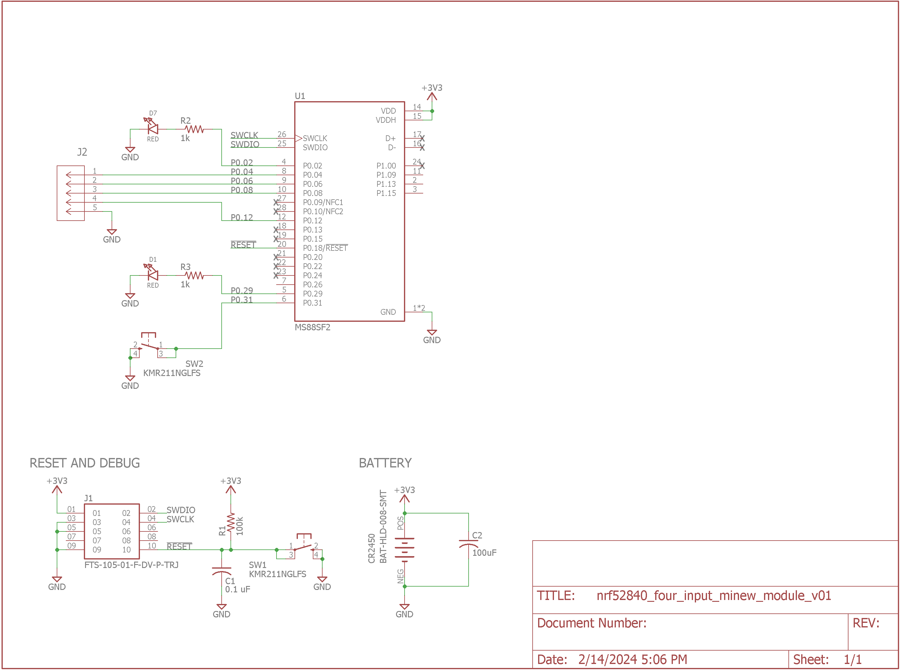
Zigbee button transmitter schematic.
The very high integration of the Minew Semiconductor MS88SF2 RF module means there’s not much to the hardware. It’s the RF module plus a few buttons, LEDs, passives, and connectors. The push button inputs are held in the high state using the nRF52840’s internal pullups. The complete schematic is shown above.
Note that the MS88FS2 is available in three different power configurations. For my battery-powered four-input Zigbee transmitter, I’m using “Configuration 3: 1.8V-3.6V to VDD.”
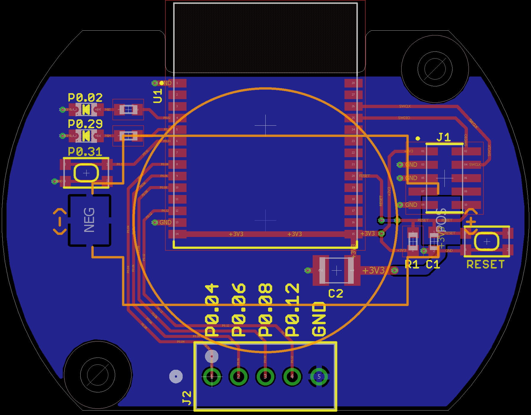
Zigbee button transmitter board layout.
The board layout is shown above. For best RF performance, the antenna should be hanging in free space and the ground plane kept clear of it. The battery holder solders to the bottom of the board.
Hardware Bring Up
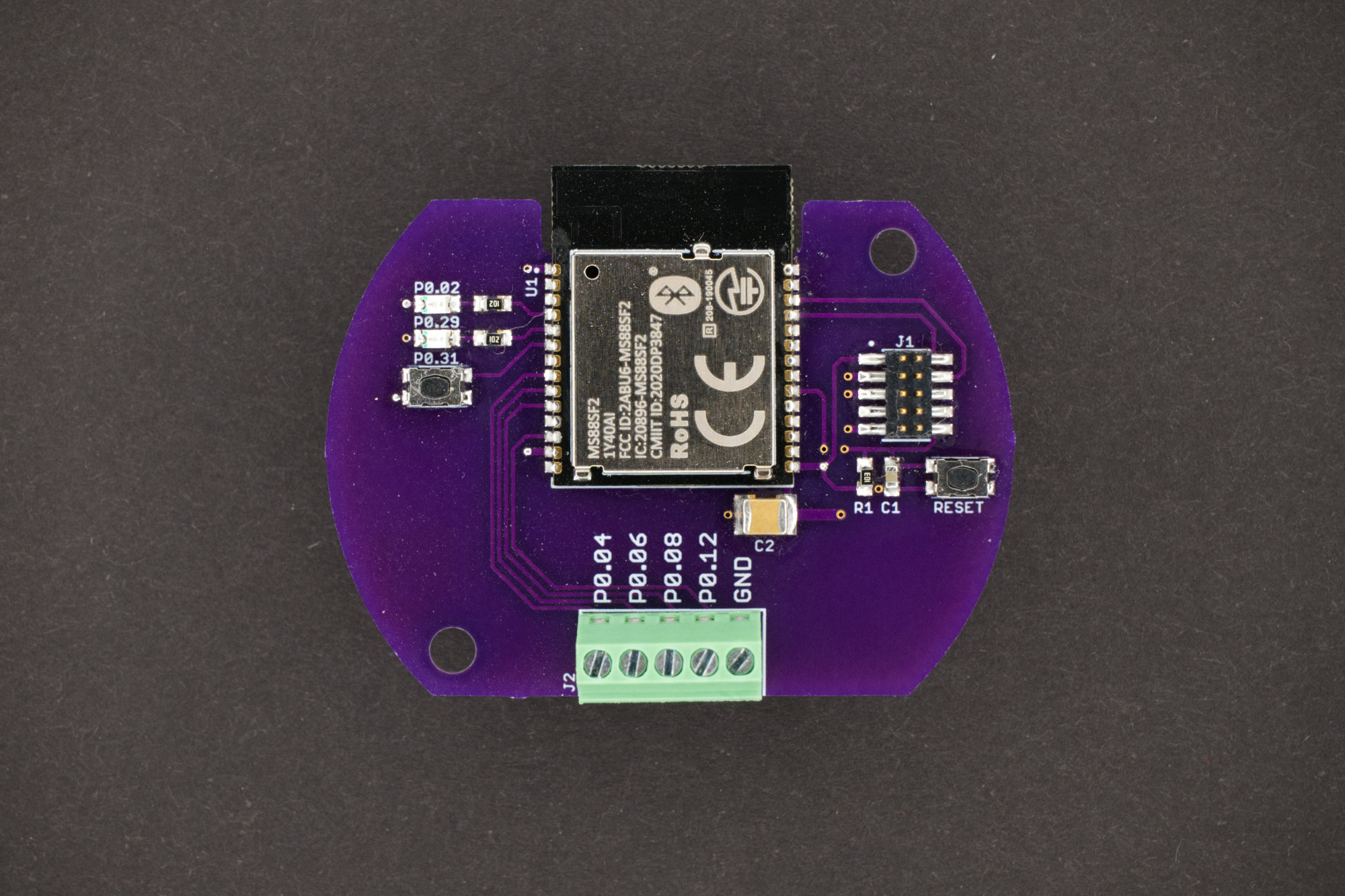
The front of the assembled Zigbee button transmitter board.
The assembled board is shown in the photograph above. The only through-hole component is the five-pin terminal strip to connect the buttons.
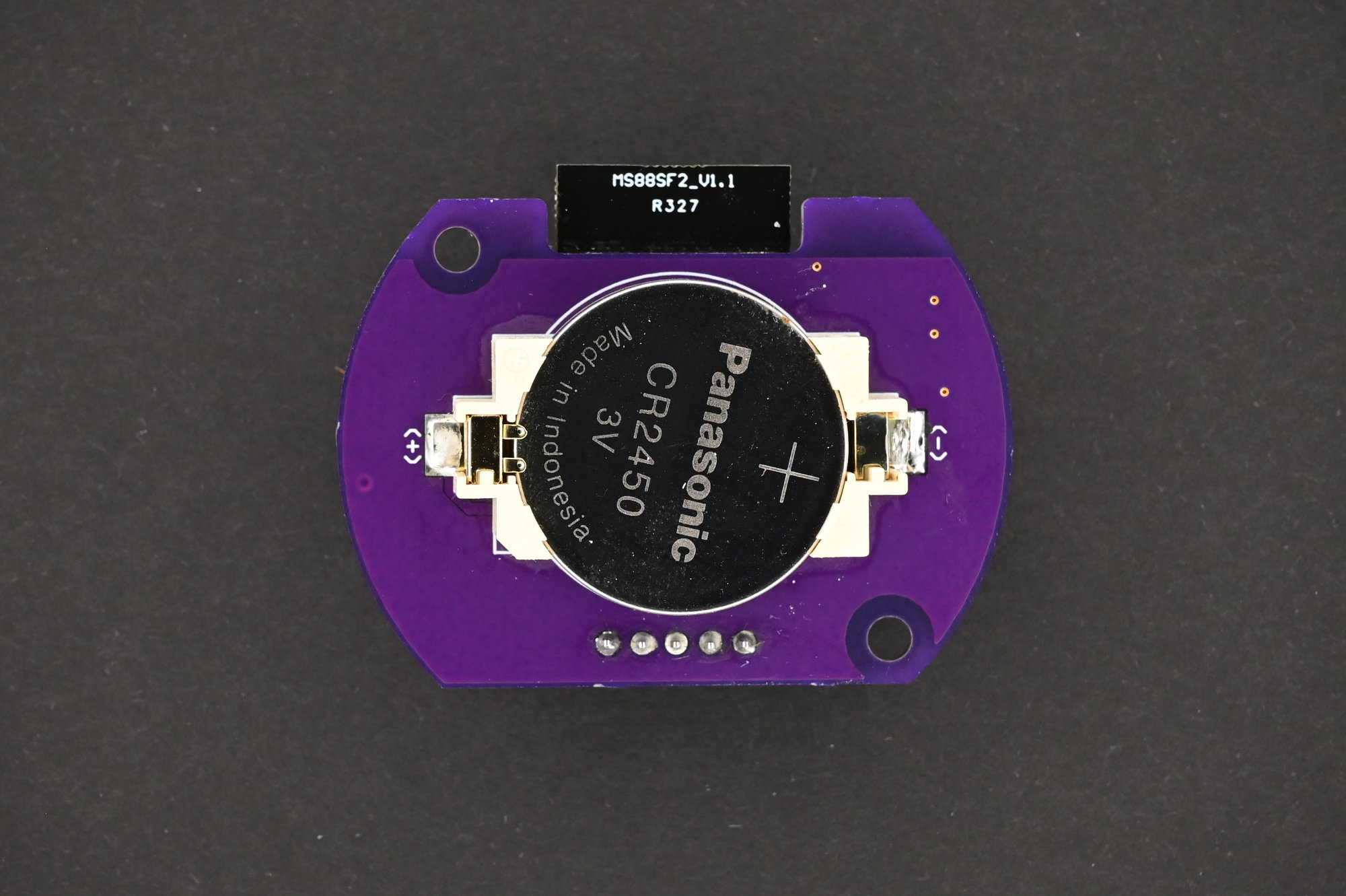
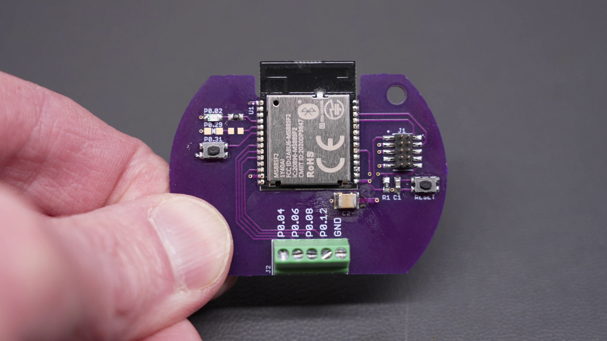
The back of the assembled Zigbee button transmitter board. Note that the wireless module’s antenna is hanging in free space and clear of the PCB, ground plane, and battery.
The photo above shows the back side of the board. The antenna is free and clear of the board, ground plane, and battery. On the next revision, I’m going to include the chamfered corner that indicates the (+) terminal of the battery holder on the silkscreen layer.
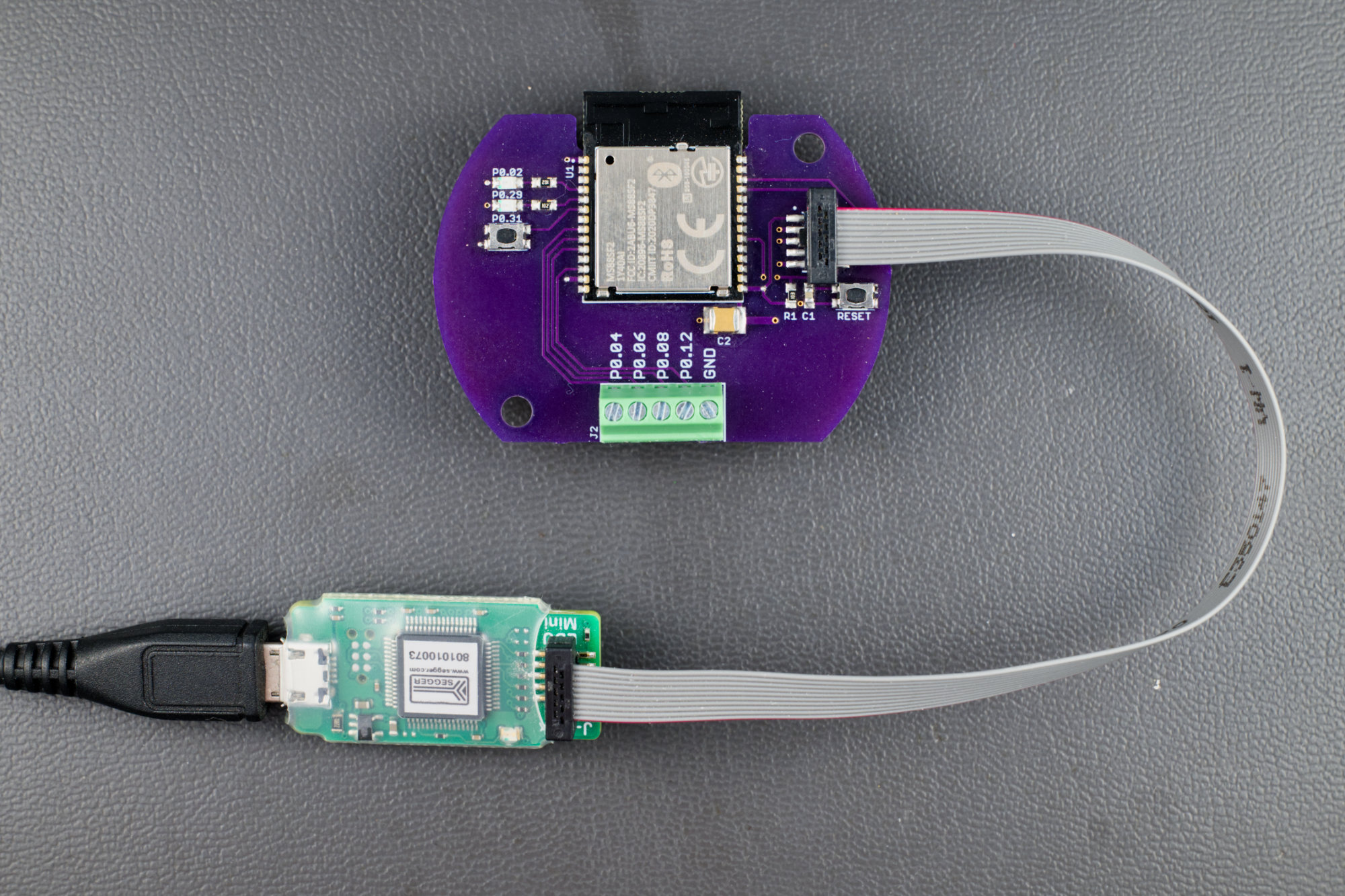
For programming and debugging, I used a J-Link Edu Mini.
For programming and debugging the nRF52840 from Visual Studio Code, I used nRF Connect Visual Studio Code plugins, version 2.5.1 of the nRF Connect SDK, and a Segger J-Link EDU Mini SWD programmer and debugger.
Programming and debugging can be done while the board is powered from the CR2450 coin cell. For board bring-up and most of the development work though, I used a current limited bench supply and some alligator clips to clip on to the battery holder’s (+) and (-) terminals.
Embedded Software Development
The hardest part of this project was the software development. The learning curve is tremendous and the nRF Zigbee library is not documented very well. I was able to leverage the examples included in the SDK to get started. From there, Otávio Ribeiro’s Zigbee Light Sensor code and Jan Gnip’s Zigbee Air Quality Monitor code were also useful, particularly for figuring out how to declare and use the extended identity Zigbee cluster library that would let Zigbee2MQTT identify and interview my module.
Since my Zigbee module is going outdoors, I wanted direct attribute reports of the battery voltage. Unfortunately, in the Zigbee cluster library, battery voltage is not a reportable attribute. It has to be polled. But if the device is asleep for 8 hours a day, good luck polling it. I could have relied on the battery percentage attribute reports only but the raw battery voltage is much more useful.
I eventually was able to kluge together a hack to wake the module from sleep every eight hours, use the ADC to measure VDD, and send an attribute report with the battery level and the battery voltage back to my Zigbee coordinator and Zigbee2MQTT. It’ll definitely fail any Zigbee compliance testing, but I can at least monitor the battery voltage during the dead of winter.
There’s a few gotchas around calling things at interrupt time vs on the main Zigbee thread and waking the scheduler from sleep. These are documented pretty well in the comments in my code.
The code uses the ZCL genOnOff cluster to report button presses and releases. Button release reports can be turned off using a #ifdef in main.c. The code uses the three defined commands (OFF, ON, TOGGLE) and five reserved values to report all eight possible button state changes. These are detailed in the table below:
| Button | Pin | Press | Release |
| 0 | P0.04 | 0x00 (Off) | 0x04 (Reserved) |
| 1 | P0.06 | 0x01 (On) | 0x05 (Reserved) |
| 2 | P0.08 | 0x02 (Toggle) | 0x06 (Reserved) |
| 3 | P0.12 | 0x03 (Reserved) | 0x07 (Reserved) |
Again, it’s not going to win any rewards for Zigbee compliance but it works!
Power Consumption
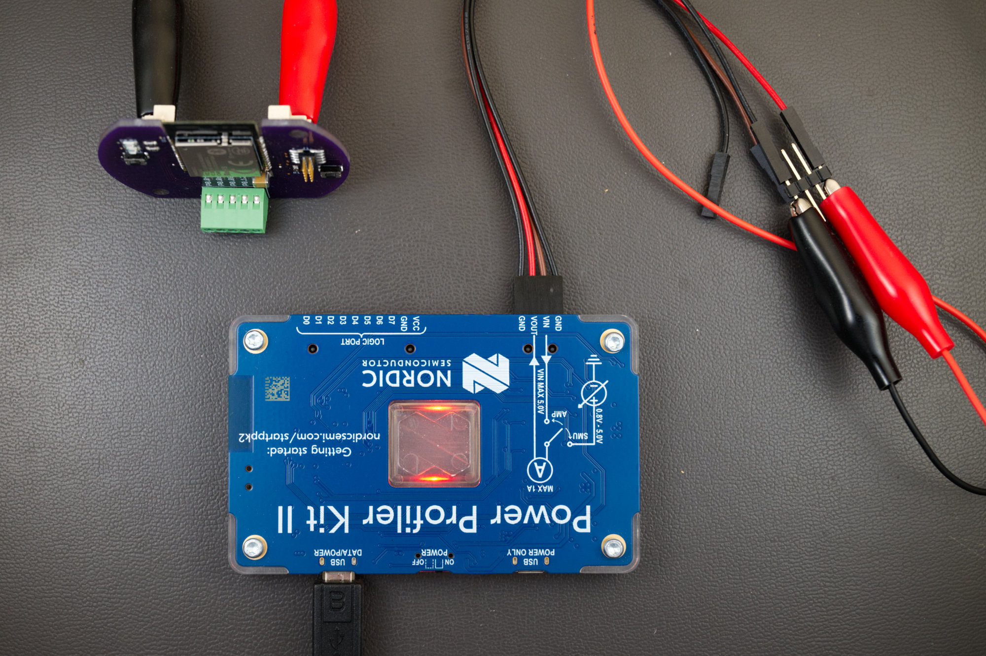
Measuring device power using a Nordic Semiconductor PPK2 power profiler kit.
If you’re serious about battery-powered design, get the Nordic Semiconductor PPK2 Power Profiler Kit! Just do it. The PPK2 supplies power and measures the connected device’s current consumption. The instantaneous current measurements are accumulated over time to derive an average current. If you let the PPK2 accumulate data over night, you can get an accurate average current value that encompasses all your device’s different modes of operation.
With the PPK2, you can also make changes to the software and see the impacts of those changes on current consumption. For example, enabling the UART for serial printf-style debugging increased the current consumption from a few μA to 600 μA. You can see that waking the microcontroller from sleep to poll for button presses consumes almost an entire mA versus a few μA sleeping and using the wake on interrupt feature. You can also see that Zigbee transmissions consume about 15 to 20 mA during the brief time while the radio is transmitting.
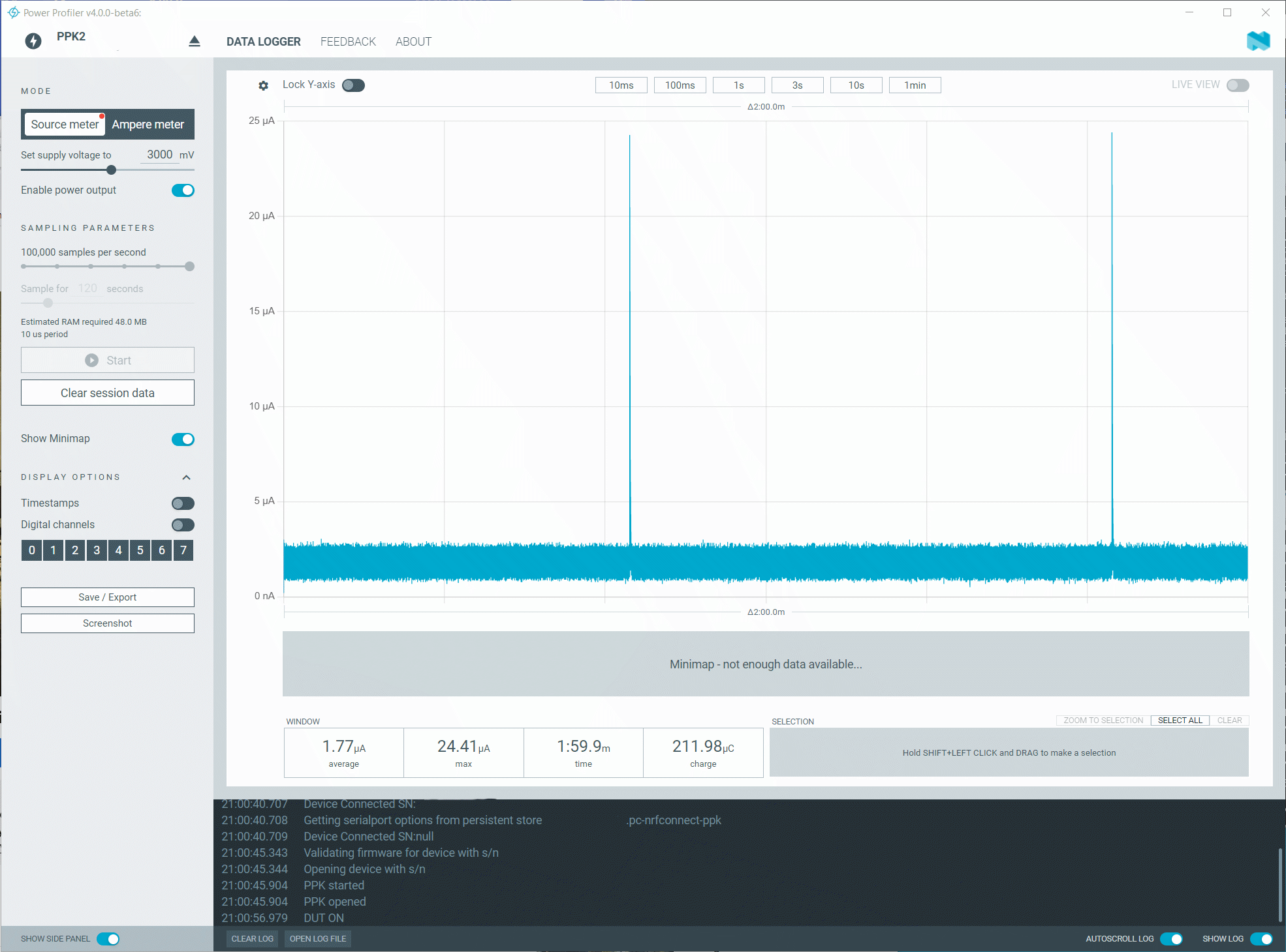
Idle current consumption is pretty good!
The screenshot above shows the average current consumption over a two minute period. 1.77 μA is pretty good! This, of course, does not show any Zigbee transmissions from periodic attribute reports or pressing buttons. If you run the PPK2 overnight, the average current consumption with a few button presses and attribute reports is about 3 μA.
A brand new CR2450 coin cell has 620 mAh of energy. 620 mAh divided by 3 μA is about 200,000 hours of operation. This is, in theory, about 23.5 years of operation from a single battery. In reality, it’ll never last that long but I’m really curious to see how long the battery does last!
You can also do this calculation using Coulombs. 620 mAh is 2232 C of charge. 3 μA is 3 μC/s. 2232/3e-6 is 744e6 seconds of operation. Divide that by 3600 seconds in an hour, 24 hours in a day, and 365 days in a year for 23.5 years!
Installation
Getting ready to install the hardware.
The photo above shows one of the completed four-input modules, programmed and powered and ready to go.
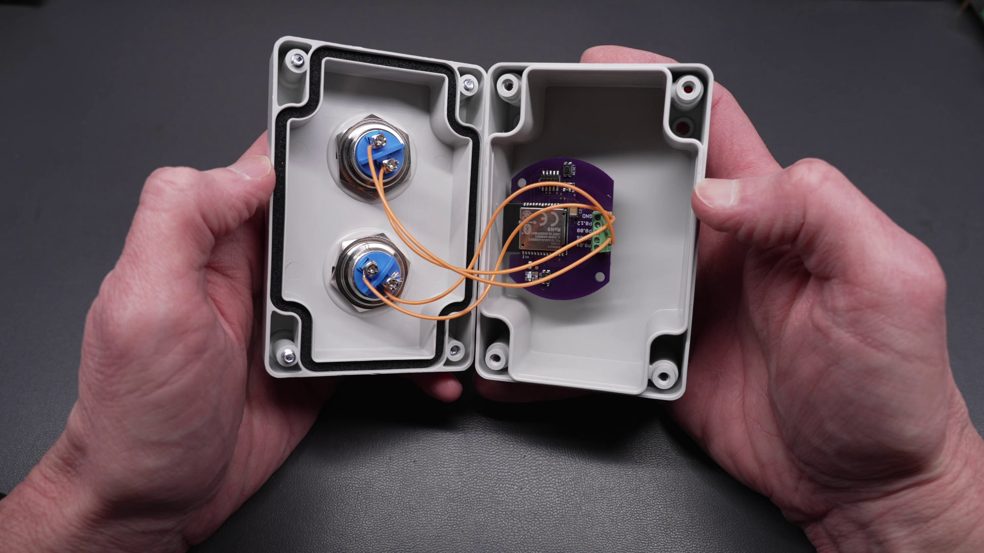
Buttons mounted to enclosure, board secured in place with a bit of tape, and the buttons connected to the board.
I secured the module to the back of the box using a short piece of 3M Command adhesive, installed the switches in the box, and wired everything up.
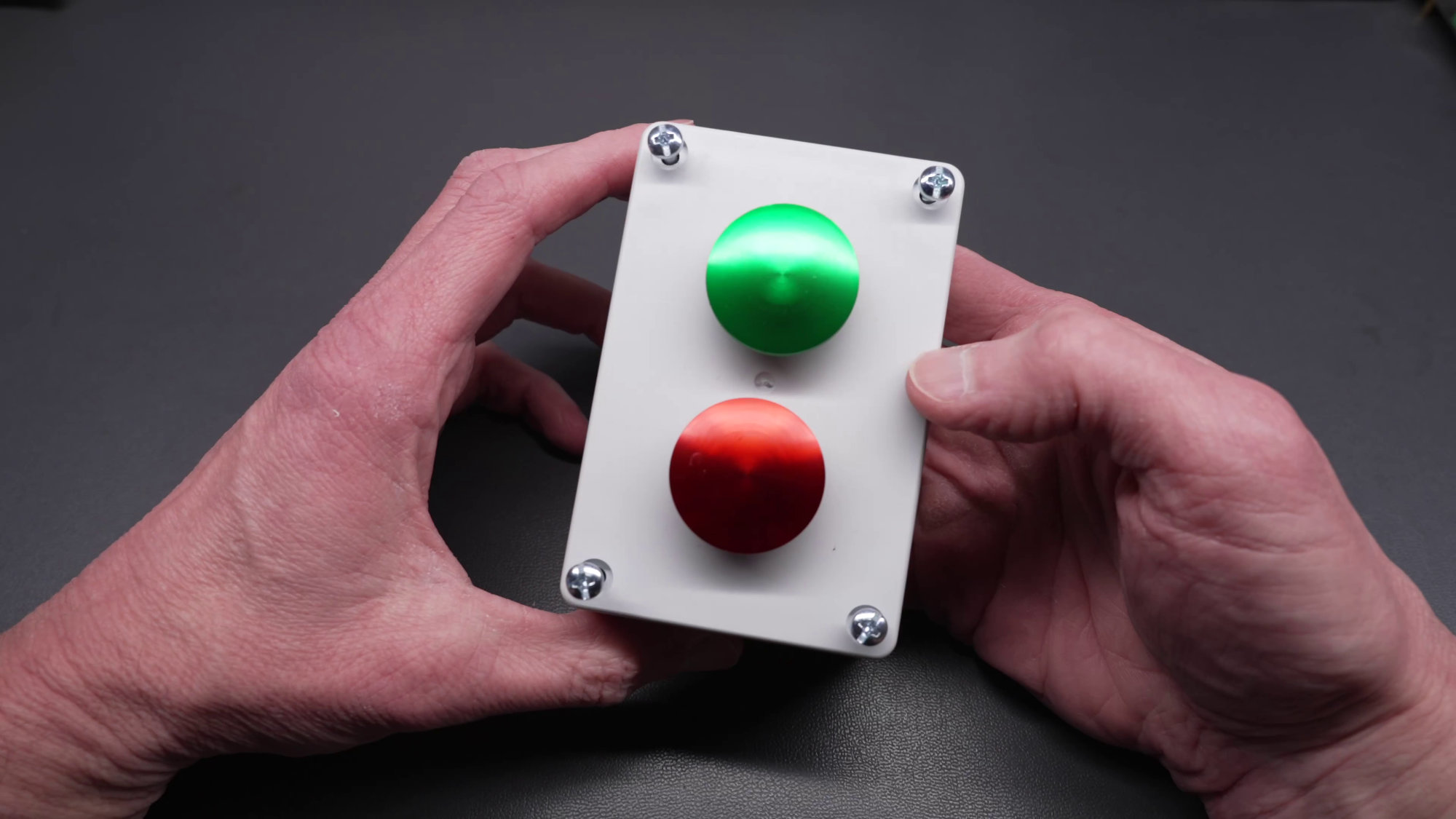
Front view of the buttons and enclosure.
The completed buttons and transmitter in their box. Since the screws for mounting the box are under the cover, hold off on tightening the cover until the box is mounted outside.
Finishing up the installation of the buttons.
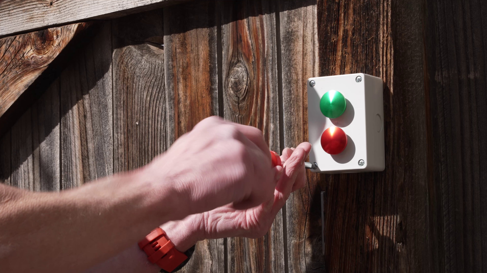
I mounted the box to a fence post just inside my back gate and secured the cover.
Linking Everything Together with Python, Zigbee2MQTT, and TinyTuya

Getting ready to mash that big green power button!
Now to make the buttons do something when they’re pressed! Integrating the buttons into Zigbee2MQTT required the creation of a custom converter. The documentation for creating custom converters is extremely lacking but the code below seems to work.
const {batteryPercentage,identify} = require('zigbee-herdsman-converters/lib/modernExtend');
const fz = require('zigbee-herdsman-converters/converters/fromZigbee');
const tz = require('zigbee-herdsman-converters/converters/toZigbee');
const exposes = require('zigbee-herdsman-converters/lib/exposes');
const reporting = require('zigbee-herdsman-converters/lib/reporting');
const extend = require('zigbee-herdsman-converters/lib/extend');
const ota = require('zigbee-herdsman-converters/lib/ota');
const tuya = require('zigbee-herdsman-converters/lib/tuya');
const {} = require('zigbee-herdsman-converters/lib/tuya');
const utils = require('zigbee-herdsman-converters/lib/utils');
const globalStore = require('zigbee-herdsman-converters/lib/store');
const e = exposes.presets;
const ea = exposes.access;

const fromZigbee_CustomActions = {
    cluster: 'genOnOff',
    type: 'raw',
    convert: (model, msg, publish, options, meta) => {
        if ((0, utils.hasAlreadyProcessedMessage)(msg, model, msg.data[1]))
            return;

        return { action: `cmd_${msg.data[2]}`};
    },
};

const definition = {
    zigbeeModel: ['four-input'],
    model: 'four-input',
    vendor: 'bikerglen.com',
    description: 'four contact closure input device',
    extend: [batteryPercentage(),identify()],
    fromZigbee: [fz.command_off, fz.command_on, fz.command_toggle, fromZigbee_CustomActions, fz.battery],
    toZigbee: [tz.battery_voltage], // permits reading voltage attribute over mqtt
    exposes: [e.battery_voltage()],
};

module.exports = definition;
I called this file four-input.js and placed it in /top/zigbee2mqtt/data. The configuration.yaml file in the same directory needs these two lines appended to the end of the file to recognize the custom converter:
external_converters:
  - four-input.js
After changing the configuration.yaml file, restart zigbee2mqtt and it should import the custom converter. At this point, the device can be added to Zigbee2MQTT by clicking join all and pressing the reset button. Once joined, the red LED on the transmitter will go out and Zigbee2MQTT should successfully interview the device. Sometimes it takes a few tries for everything to proceed smoothly.
If you connect MQTT Explorer to the same MQTT broker as Zigbee2MQTT and press the buttons, you should now the actions shown in the table below for each button press or button release (if releases were compiled into the binary):
| Button | Pin | Press | Release |
| 0 | P0.04 | “action”:”off” | “action”:”cmd_4″ |
| 1 | P0.06 | “action”:”on” | “action”:”cmd_5″ |
| 2 | P0.08 | “action”:”toggle” | “action”:”cmd_6″ |
| 3 | P0.12 | “action”:”cmd_3″ | “action”:”cmd_7″ |
Finally, the Python code below can be used to connect to the MQTT broker, subscribe to the button press/release messages, and toggle the pathway lights on or off using TinyTuya. The following items in the code need to be set for your specific network and device:
- The MQTT broker’s IP address (192.168.X.X below).
- The pathway light’s ID, IP address, and local API key from the TinyTuya poll of the device on your network (<TT_LOCAL_ID>, 192.68.X.X, and <TT_LOCAL_KEY> below).
- The MAC address of the Zigbee module from Zigbee2MQTT (0x<ZIGBEE_DEVICE_MAC> in two places below).
import concurrent.futures
import paho.mqtt.client as mqtt
import json
import tinytuya

MQTT_HOST           = '192.168.X.X'
MQTT_PORT           = 1883

ttdevs={}
ttdevs['bike_stand_floods'] = ("<TT_LOCAL_ID>", "192.168.X.X", "<TT_LOCAL_KEY>")

thread_pool = concurrent.futures.ThreadPoolExecutor(max_workers=32)


#----------------------------------------------------------------------------------------------
# mqtt on_connect
#

def on_connect (self, userdata, flags, rc, trash):
  print ("Connected with result code " + str(rc))
  # Minew nRF52840 module
  result = self.subscribe ("zigbee2mqtt/0x<ZIGBEE_DEVICE_MAC>", 0)


#----------------------------------------------------------------------------------------------
# mqtt on_message
#

def on_message (self, userdata, msg):
  print (msg.topic + " " + str (msg.payload))

  # Minew nRF52840 module
  if msg.topic == "zigbee2mqtt/0x<ZIGBEE_DEVICE_MAC>":
    if msg.payload:
      parsed = json.loads (msg.payload);

      if 'action' in parsed:

        if (parsed['action'] == 'on'):
          thread_pool.submit (tuya_floods, 'bike_stand_floods', True)
        elif (parsed['action'] == 'off'):
          thread_pool.submit (tuya_floods, 'bike_stand_floods', False)


#----------------------------------------------------------------------------------------------
# turn tuya floods on or off
#

def tuya_floods (name, on):
  print ("sending " + ("on" if (on) else "off") + " request to " + name + "...")

  d = tinytuya.BulbDevice(ttdevs[name][0], ttdevs[name][1], ttdevs[name][2])
  d.set_version(3.3)
  d.set_socketPersistent(False)

  if on:
    d.turn_on()
    d.set_white()
  else:
    d.turn_off()

  print (("on" if (on) else "off") + " request to " + name + " done.")


#----------------------------------------------------------------------------------------------
# main
#

if __name__ == "__main__":

  client = mqtt.Client (client_id="", userdata=None, protocol=mqtt.MQTTv5)
  client.on_connect = on_connect
  client.on_message = on_message
  client.connect (host=MQTT_HOST, port=MQTT_PORT)

  client.loop_forever ()
The Final Result
Here’s a video of of this project. It’s a minute and a half long. If you want to skip to the Zigbee stuff, fast forward to about 40 seconds.
The video embedded above covers the entire project from motivation, through the use and installation of the lights and Zigbee buttons, and the final result. If you want to skip to the Zigbee stuff, fast forward to about 40 seconds.
Design Files
The design files are available on Github in my Zigbee homebrew four-input repository.
Disclaimer: Glen may earn compensation for sales from links on this post through affiliate programs.