
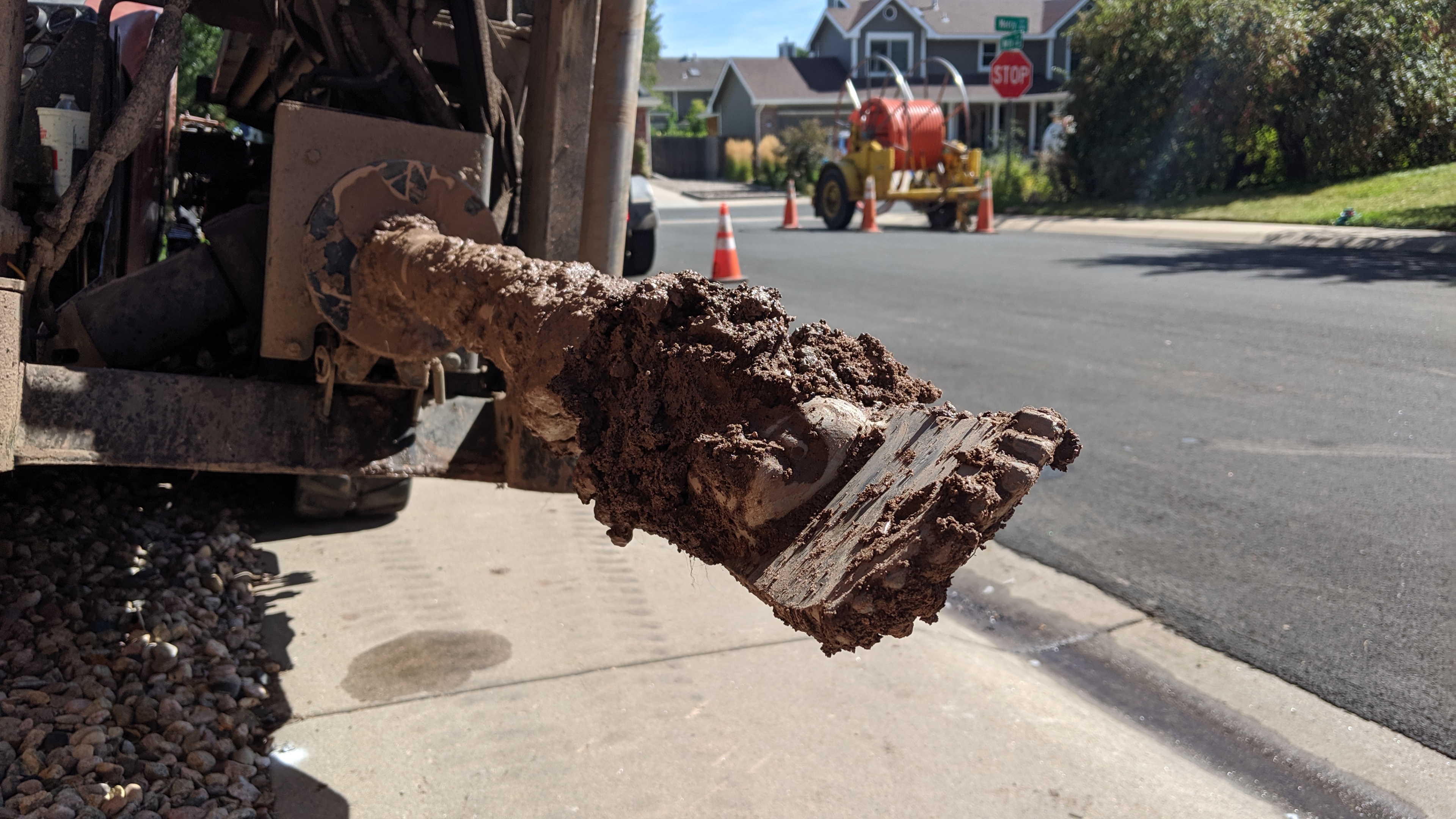
The business end of a horizontal drilling machine’s drill head.
In part one of this series of posts, we covered the broadband launch, the start of construction in my neighborhood, the vaults and flowerpots, utility locates and dig ins, and conduit. In part two, we’re going to look at putting the conduit in the ground using horizontal directional drilling and then we’ll continue to document everything as construction moves forward. Read on to hear more about the process as the build in my neighborhood continues.
September 25 – Horizontal Directional Drilling
The bulk of the conduit installation was completed on my street last week. They still need to come back and install conduit under and across the street in a few places and install conduit in my cul-de-sac. To install the conduit, crews bored a hole through the ground then pulled the conduit back through the freshly drilled hole.

Horizontal directional drilling machine at work in my neighborhood.
The drilling technique they’re using is known as horizontal directional drilling or simply directional boring. This technique lets crews dig a 300 to 600 foot long horizontal hole in the ground for the new conduit without having to dig trenches and tear up streets and sidewalks. This technique also lets crews minimize the damage to lawns and other landscaping. A horizontal directional drilling machine is shown in the above photo.
The word directional in the name of the technique refers to the fact that the drill head can be steered to change the direction of the hole as it’s being drilled. Crews start by planning a path for the hole. The goal is to bury the new conduit two to three feet below ground while staying at least one to two feet away from any existing utilities. While drilling the hole along the path, crews can steer the drill head up and down to avoid existing utilities or left and right to follow the contour of a sidewalk or street.
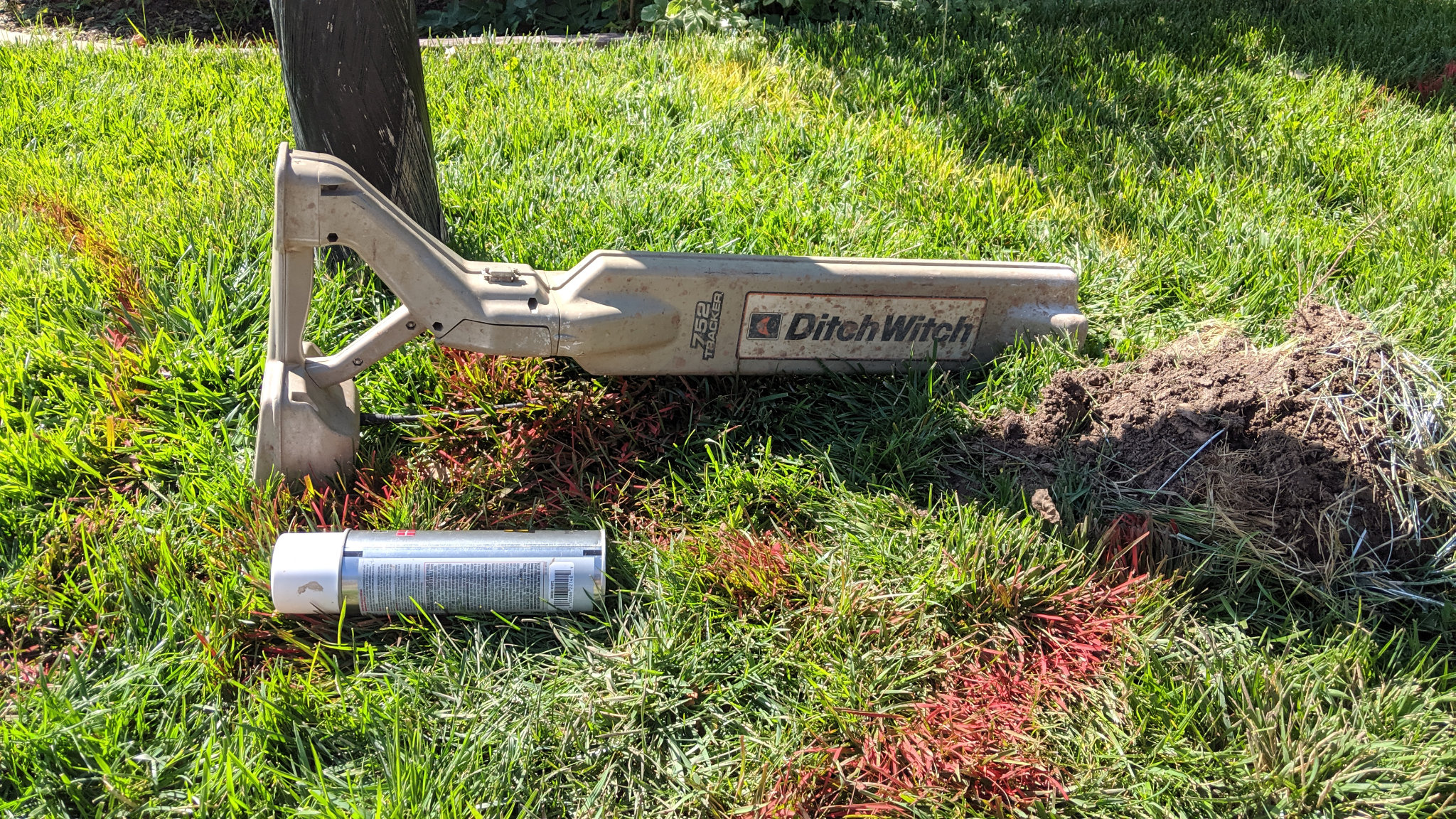
The tracker is critical to locating and steering the bit while performing directional boring.
Critical to steering the drill bit around obstacles and staying on the planned path is knowing the location, depth, and orientation of the drill head during the drilling process. In the tip of the drill head is a beacon. The beacon broadcasts a radio signal which can be detected by a tracker like the one shown in the above photo.
While drilling, the drill operator sits at the controls on the drilling machine and controls the rotation and thrust of the drill bit. A tracker operator then walks along the drill path with the electronic tracker. Periodically drilling is stopped and the tracker operator locates the position, depth, and orientation of the bit. Any needed course corrections are relayed to the drill operator who steers the drill head to make the necessary corrections and drilling resumes.
(If you missed it earlier, in part one of this series, we talked about using utility locates and keyholes to locate underground obstacles to avoid during the drilling process.)
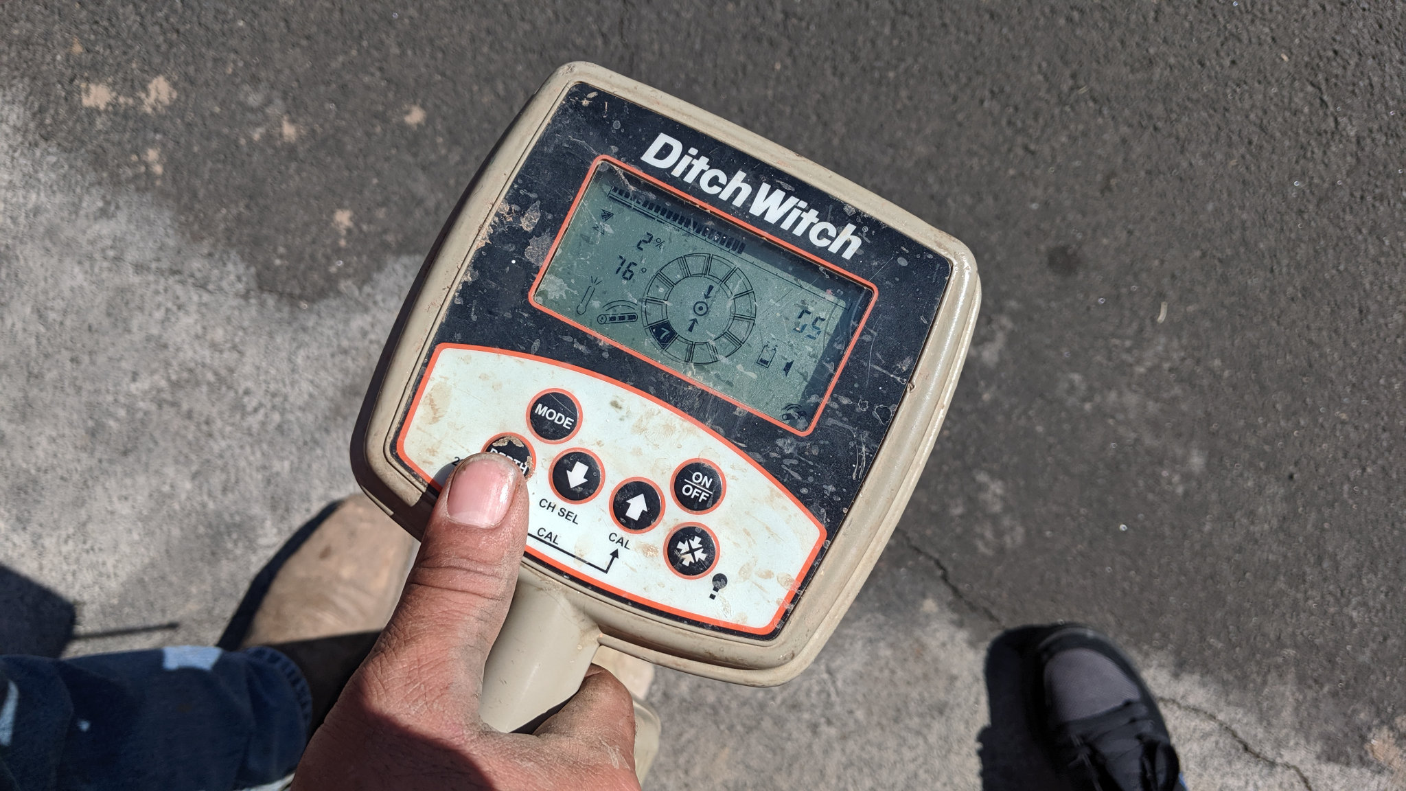
The screen on the top of the tracker. This information is relayed electronically to the drill operator who has an identical screen at their controls.
The screen on the tracker is shown in the above photo. In this case, the tracker is located directly over the drill head and the depth is about five feet. The center circle in the display indicates the orientation of the drill head and consequently the direction the drill head is being steered. Like the hours on a clock, 12 is up, 3 is right, 6 is down, and 9 is left. In this case, the circular display indicates seven so the drill head is being steered down and to the left.
But what actually makes the drill head change direction? The drill operator only has three things under their control: the rotation of the drill head, the thrust or forward force of the drill head, and the amount of mud being pumped out of the tip of the drill head. None of those alone is enough to steer the drill head. The key lies in the shape of the drill head.
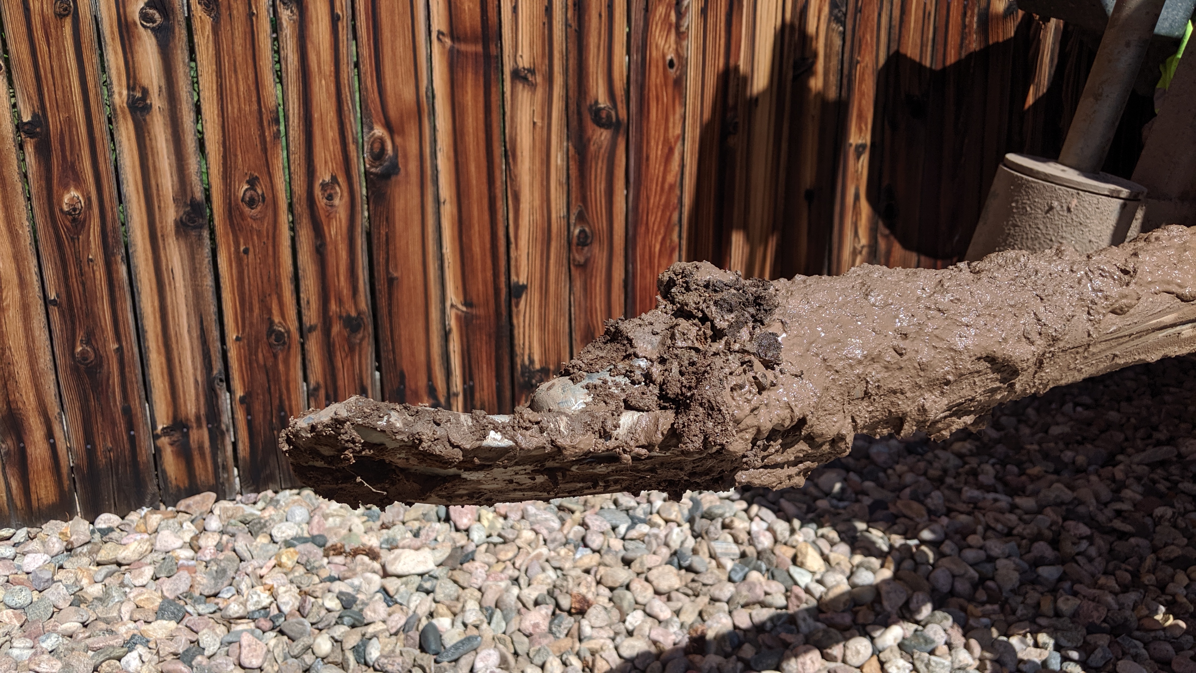
Directional boring machine drill head. It’s very muddy even after the technician scraped off enough mud to make out the details of the drill head. The radio beacon is located in a sealed chamber towards the right side of the photo.
If you look at the photo above, you can see that the drill head is not symmetrical. It has an angled face on one side. If the operator uses thrust to push the drill head into the ground without rotating the drill head, the drill head will be deflected away from the angled face. If this bit were underground and the operator applied thrust without rotation, the drill head would be deflected up and away from the camera. Once the drill head is deflected to the desired direction, the operator applies thrust with rotation to drill the hole along the new direction.
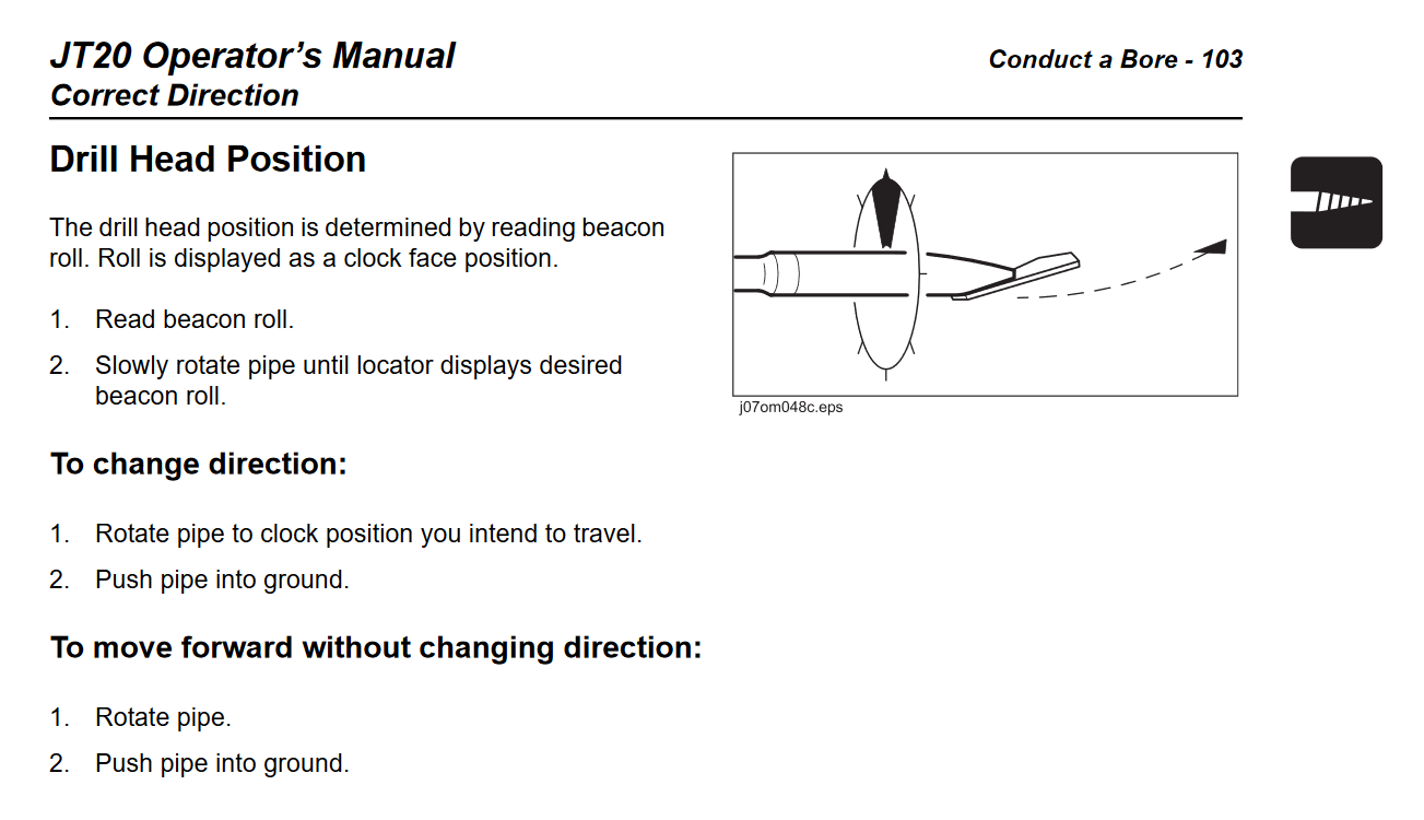
The correcting drill head direction page from a horizontal drilling machine’s operator’s manual. Source: Ditch Witch.
The instructions above are from a Ditch Witch horizontal directional drilling machine’s operator’s manual. In the inset image, you can see the clock indicator from the tracker superimposed around the drill bit. You can also see the angled surface of the drill head. The dashed line arrow indicates the direction the drill head will deflect when thrust is applied without rotation.
The ability to steer the drill head and direction of the hole underground comes down to the ability to accurately determine the orientation of the drill head using the tracker, to rotate the drill head to the correct orientation, and to push the drill head forward through the ground without rotating it.

The business end of a horizontal drilling machine’s drill head.
To help with the drilling process, there’s a high-pressure water jet just behind the tip of the drill head. It’s circled in blue in the above photo. High pressure water is pumped down the drill pipe and exits the drill head through this hole. The water helps to break up the soil around the drill head, serves as lubrication and coolant for the possibly hundreds of feet of rotating drill shaft in ground, and pushes the excavated material out of the drilled hole and back toward the machine operator.
After drilling is complete and the drill head emerges from the ground at its destination, it’s time to pull the conduit back through the freshly bored channel. One end of a chain with a freely rotating swivel joint is threaded through a hole in the drill head. The hole is about an inch back from the tip and is circled in red in the photo above.
The other end of the chain is connected to a fitting attached to the end of the conduit. The photo below shows the fitting mounted on the end of a piece of conduit. The drill pipe with the conduit attached is then rotated and pulled back through the bored channel toward the machine’s operator. This action pulls the conduit into the bored channel and the conduit is now buried underground with minimal disruption to surface activities.
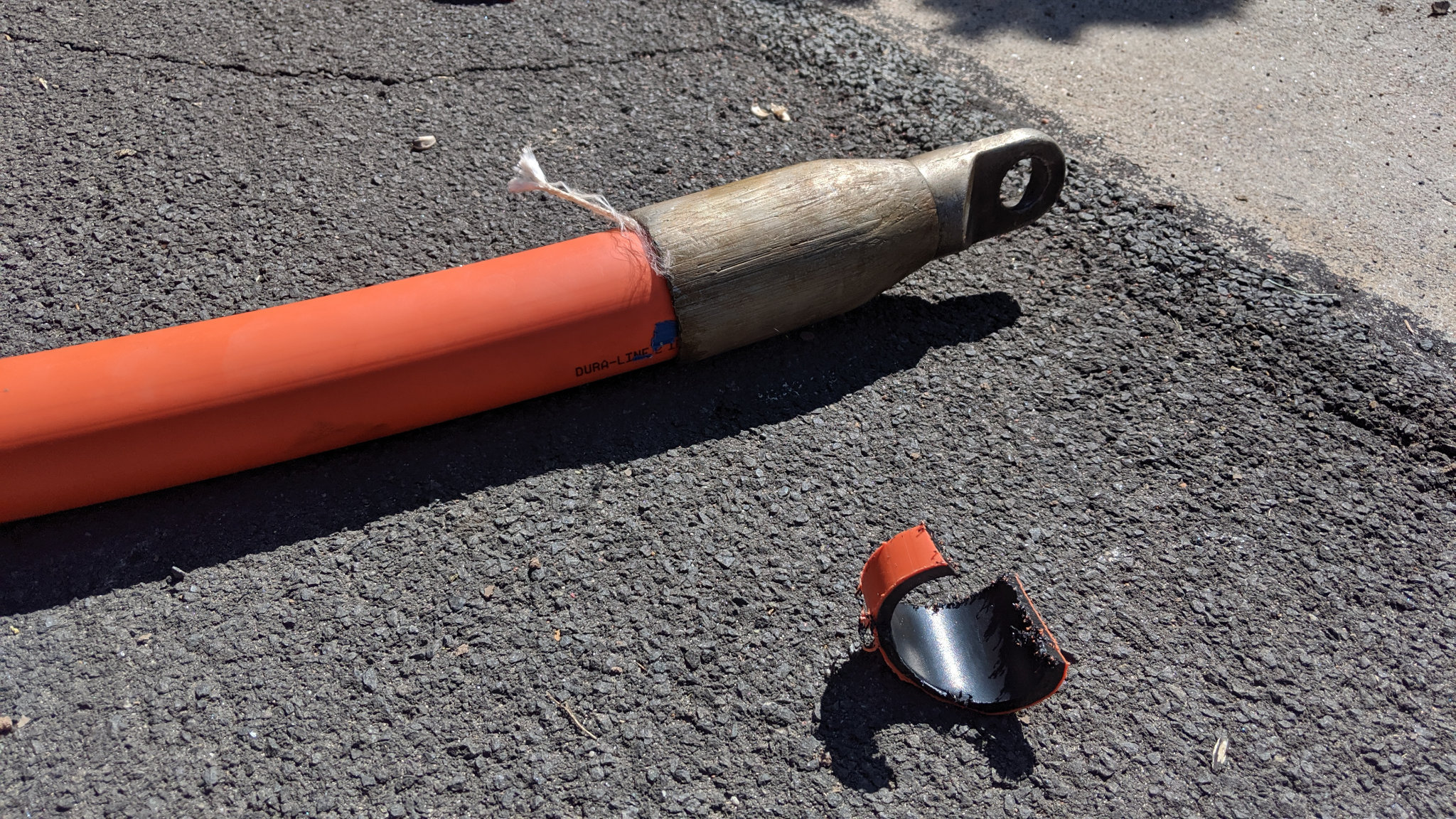
Conduit with fitting attached and ready to be pulled back through the freshly bored hole.
I’ll continue to update the part two blog post with updates as work continues in my neighborhood. Lastly, I cannot thank the contractors at AEG and their subcontractors like RR Drilling LLC out of Brighton enough for explaining the process and letting me take these photos between drilling sessions. Part two continues soon!
September 26 – Even Moar Horizontal Directional Drilling
More directional boring occurred in my neighborhood today. They started pulling short runs of conduit from one side of the street to the other. They also installed conduit in the cul-de-sac on the opposite side of the street from me. Maybe they’ll install conduit in my cul-de-sac this week or the next.
October 1 – Some Boring Activity on My Cul-De-Sac!
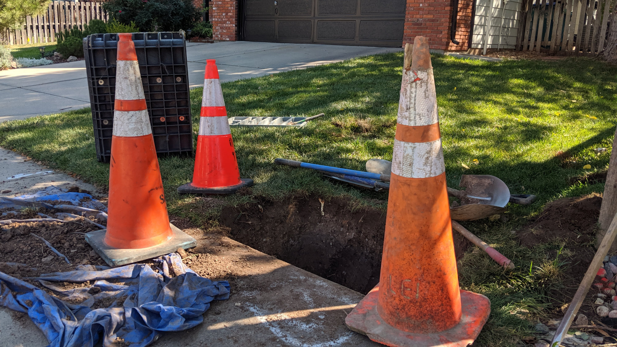
Last Thursday I got excited! On my way out the door to leave for work, the construction crews with their horizontal directional drilling rig showed up in my cul-de-sac. While I was at work, they marked a few locations for keyholes like this one directly in front of my driveway.
They’ll eventually dig a keyhole to locate the depth of the water pipe leading to my house.
They also pulled conduit a third of the way around the cul-de-sac but stopped one house over from me. They pulled two pieces of 1-1/4″ conduit and topped them off with an orange construction cone. The photo below shows the conduit. You can see the white pull tape that will be used to pull fiber through the conduit at a later point in time.
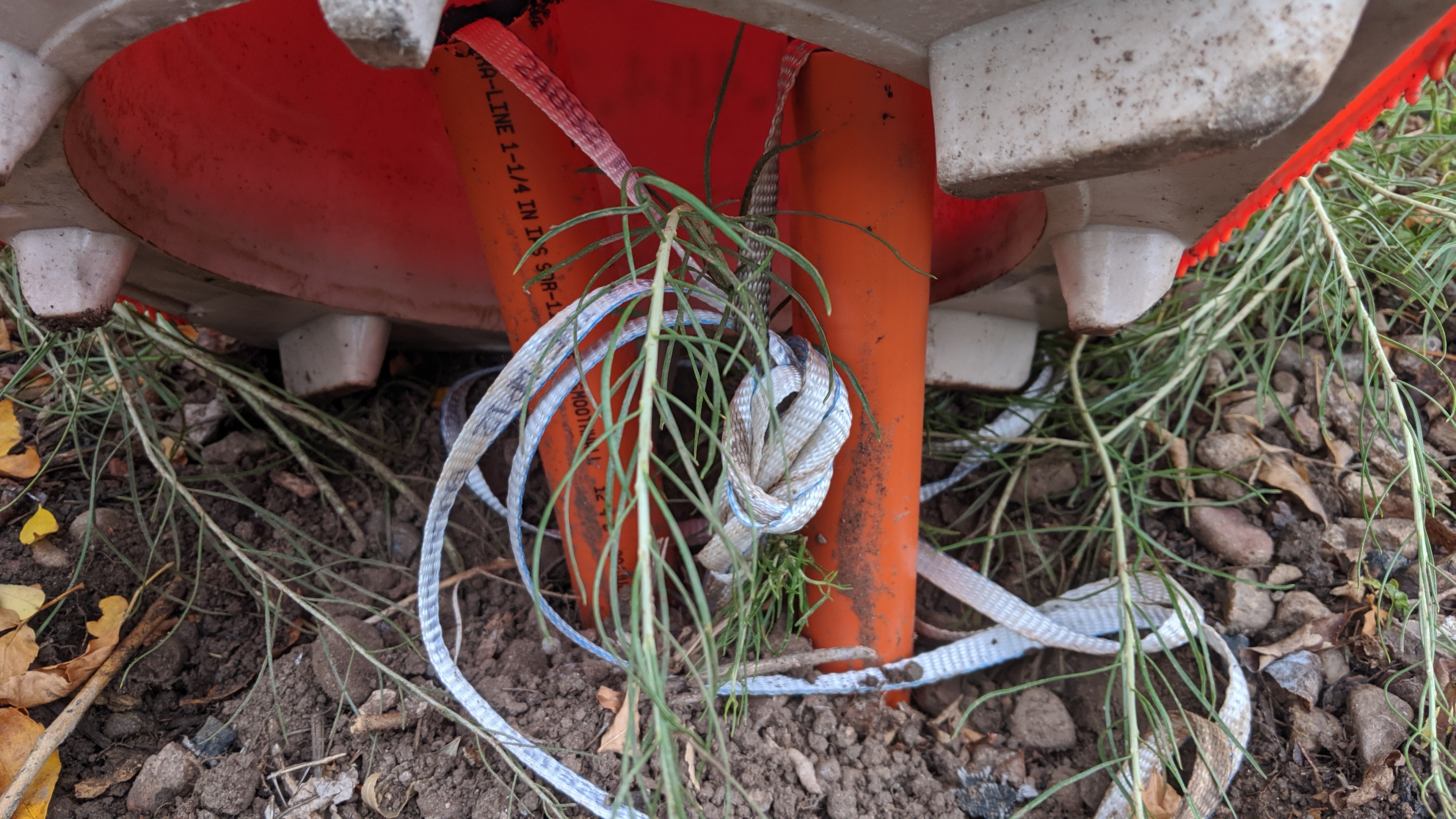
Two pieces of 1-1/4″ conduit with pull tape exposed above the surface one house over from me.
Then a surprise. I found this flowerpot directly across the street from me. It’s almost completely obscured by a neighbor’s sprinkler. It’s the first splice vault or flower pot on my street.

Flowerpot across the street from me.
I’m hoping that maybe this week or the next they’ll finish pulling conduit the rest of the way around the cul-de-sac. Maybe they’ll bring in the smaller missile boring equipment to do it. We shall see. In the meantime, stay tuned!
October 11 – Vaults Nearby But Still no Conduit on Our Cul-De-Sac
This past week they started installing vaults and flower pots on our side of the street. Unfortunately there’s still been no progress on installing flower pots or pulling conduit the rest of the way around our cul-de-sac. It looks like they’ve skipped flower pots and conduit serving about eight houses on this side of the street.
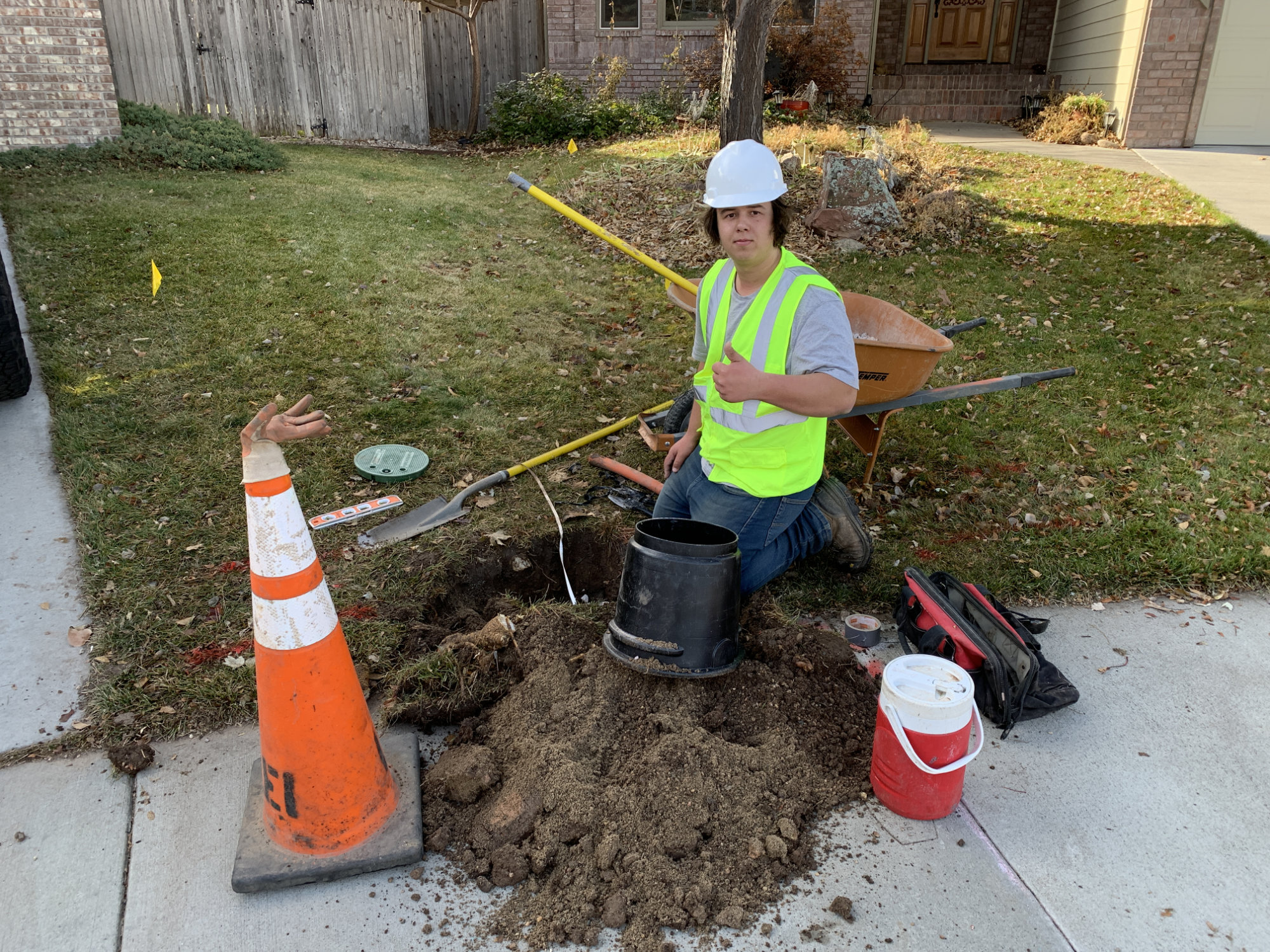
Unlike installing the conduit, placing the fiber splice vaults is a manual process involving good old picks and shovels.
Unlike installing the conduit, placing the fiber vaults is a manual, labor-intensive process involving good old picks and shovels. A two-person crew digs a big rectangular hole using picks and shovels as seen in the above photo.
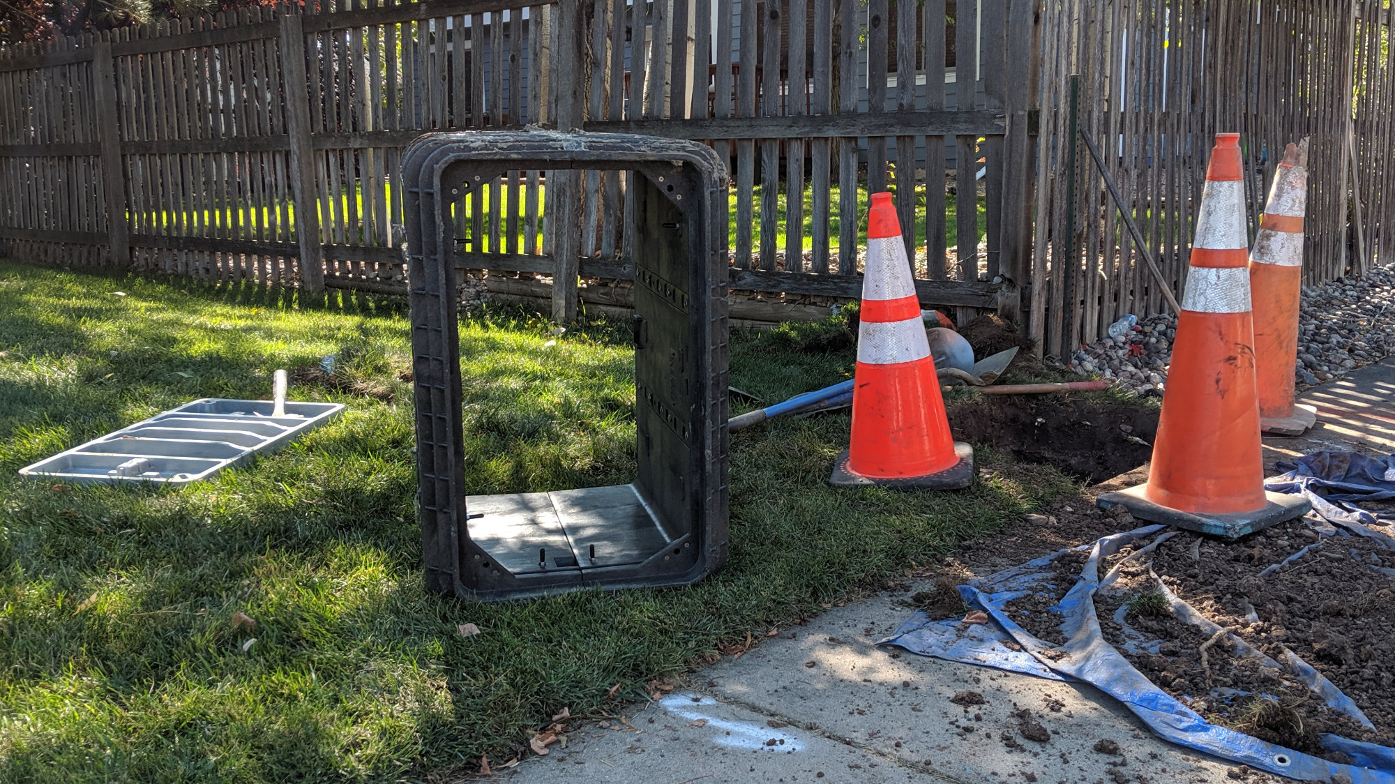
The vaults don’t have bottoms to keep
Once the hole is dug, the splice vault is buried and the conduit previously placed in the area is pulled up through the bottom of the vault.
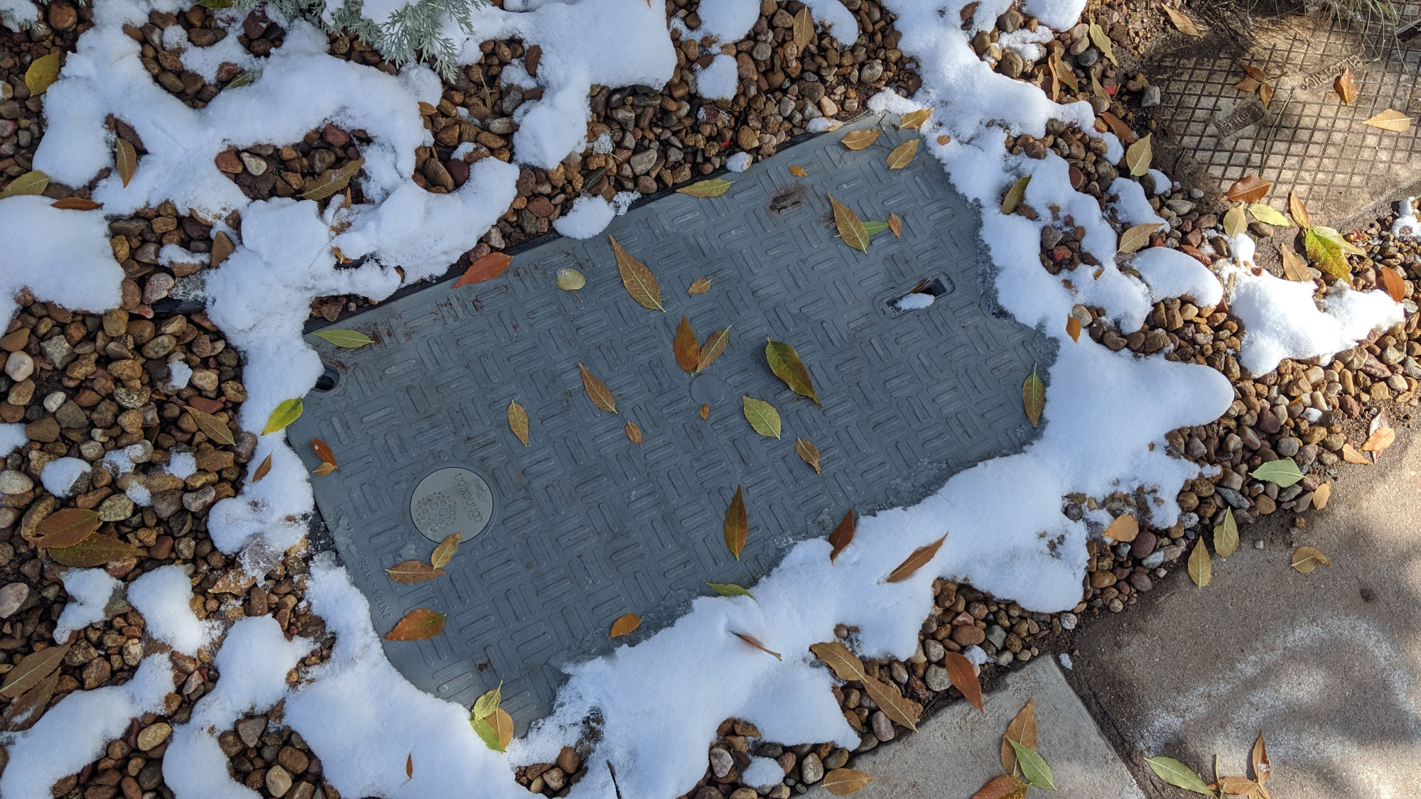
Finished vault installation with landscaping around the vault restored.
Finally a cover is placed on the vault (complete with the Connexion logo) and the landscaping around the vault is restored.
October 17 – Xcel Energy Locates Gas Lines
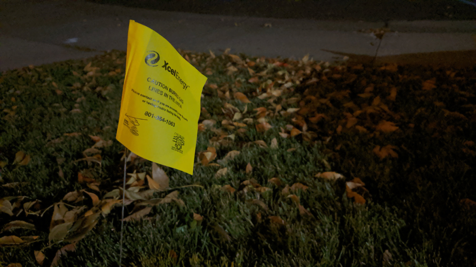
Xcel Energy gas line locate flag in my front yard.
I got home last night to find that Xcel Energy located the gas lines in the cul-de-sac. I’m not sure why they didn’t do this when they did the rest of the street a few weeks ago but they’re done now. Also the city re-marked the electric, water, and sewer locates. Maybe this means they’ll finish installing conduit in the cul-de-sac soon.
November 1 – Conduit Installed in Cul-De-Sac
Today the drilling crews came to our cul-de-sac and installed conduit underneath the street to where the flower pot will be between my house and the house northwest of me!
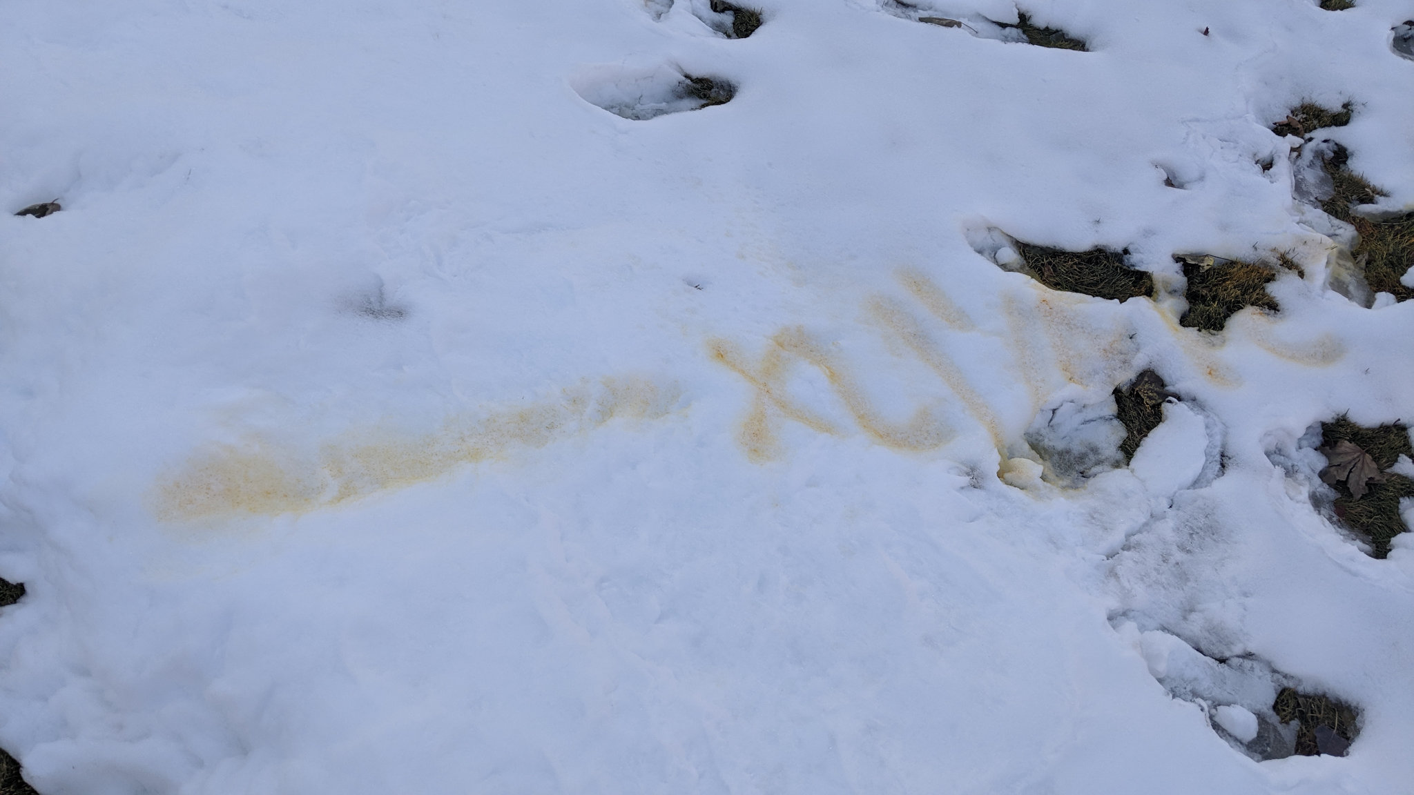
Utility locates in the snow.
This past week, we had a lot of snow and cold temperatures considering it was only the end of October. We were concerned they would not be able to do much work until the snow melted primarily because the utility locates were all painted on the road and grass underneath the snow. That didn’t slow them down. Some last minutes locates were done in the snow and the crews were able to resume work.
Crews dig keyholes to locate existing utilities as directional boring work commences on my cul-de-sac. The core drill is on the left by the guy in the yellow vest.
They started by digging some keyholes to determine the depth of the existing utilities in the area. The photo above shows them digging a keyhole to locate the depth of an existing water line.
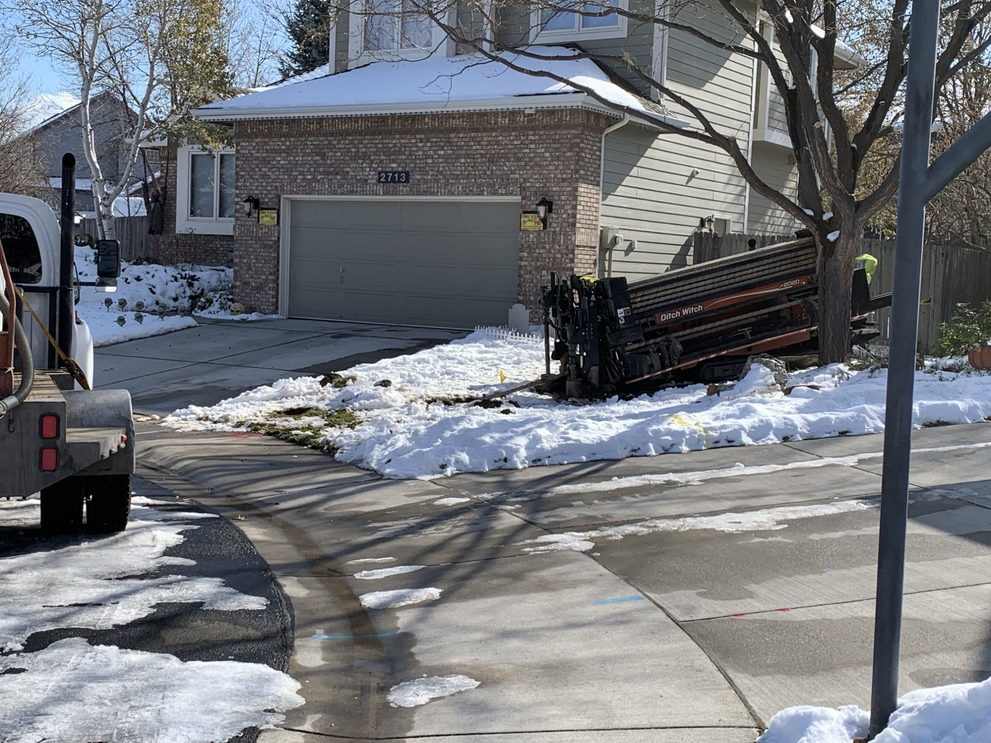
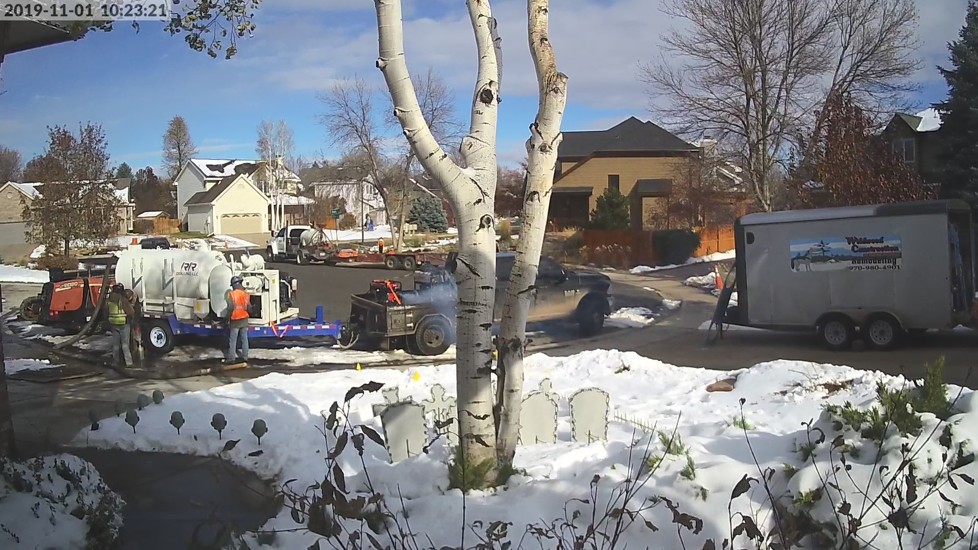
The horizontal directional drilling equipment in my neighbors yard. It’s aimed straight across the cul-de-sac toward some existing conduit. The Halloween decorations are still out since it’s just the day after Halloween. Image courtesy one of my neighbors.
While the keyholes were being dug, they backed the horizontal directional drilling equipment up into my neighbors yard and aimed straight across the cul-de-sac toward some existing conduit.
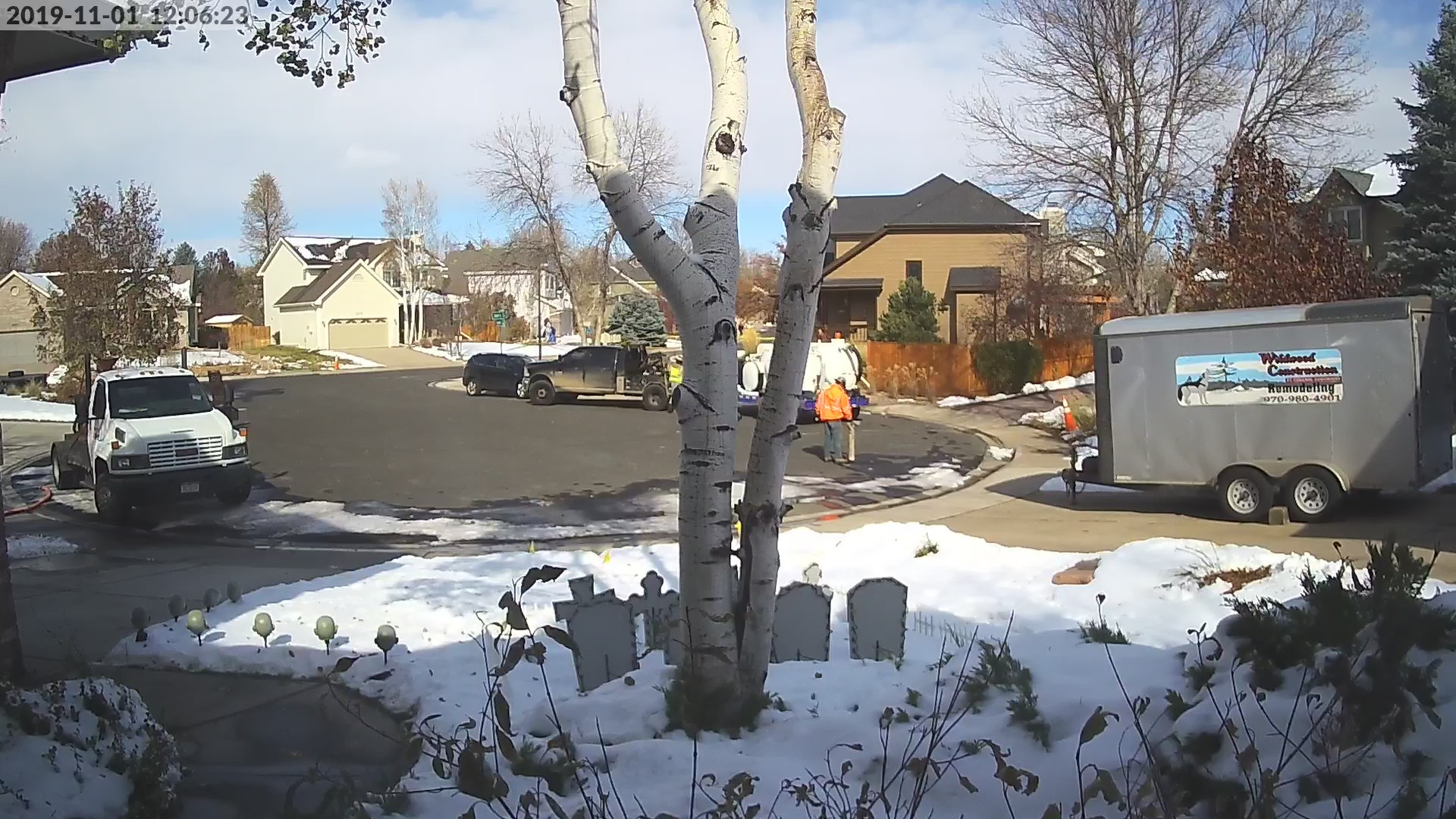
A Connexion contractor locates the horizontal directional drilling rig’s drill head underneath the cul-de-sac.
They then bored straight across the cul-de-sac. The snapshot above shows the guy with the tracker locating the drill head as it bores underneath the street.
A short length of conduit placed near the end of the drilled channel.
Once they were across the cul-de-sac, a guy dropped off a length of conduit near the end of the bored channel. They attached the conduit to the drill head and then pulled the conduit back through the bored channel.
One of the major milestones I’ve been waiting for: this piece of conduit will eventually connect a flower pot in my front yard to the rest of the network.
Voila! Here’s the end of the conduit poking up out of the ground between my house and the house northwest of me. Eventually this will be routed a bit closer to the curb and a flower pot will be installed to provide access to the conduit. That will complete the work this crew will do in our cul-de-sac.
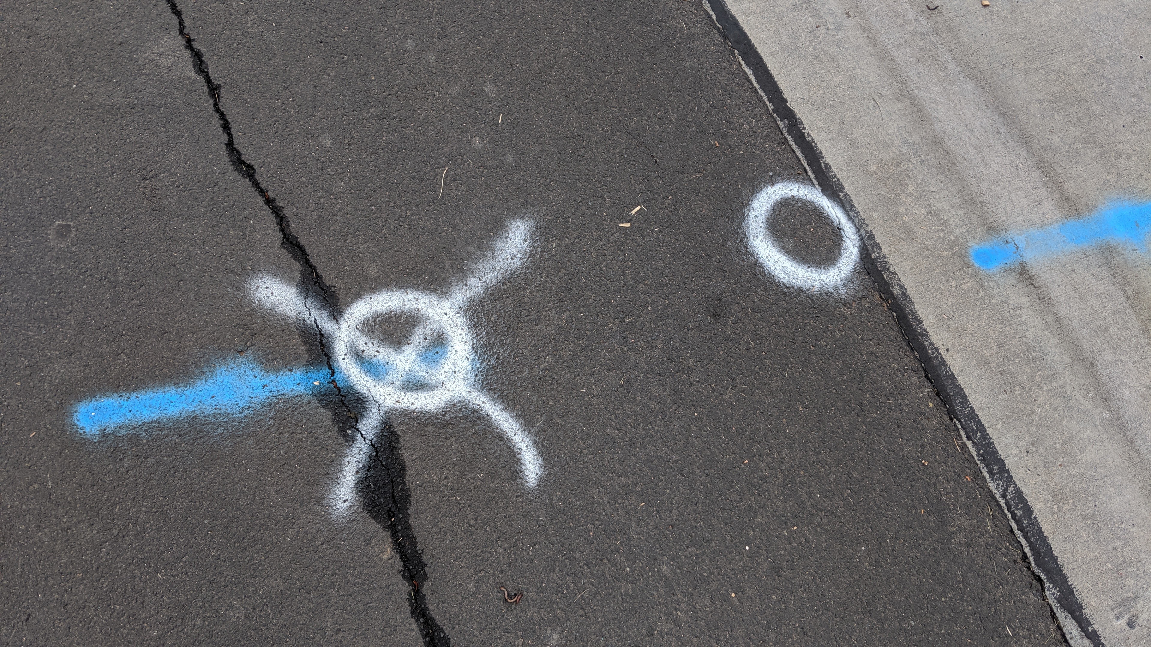
In this image, the conduit route is a orange line and the splice vaults and flower pots that provide access to the conduit are blue stars. They can reach every house on the cul-de-sac without going underneath a sidewalk or driveway except the house on the northwest corner that is labeled as the isolated house. (Satellite imagery from Google Maps.)
My neighbor’s house on the very northwest corner of the cul-de-sac is still isolated. Our current thinking is a different crew will come back with missile boring equipment and place conduit from the flower pot location, under our mutual neighbor’s driveway, and then trench to his house when he orders service. Looking around the neighborhood, this seems to be a pretty common occurrence.
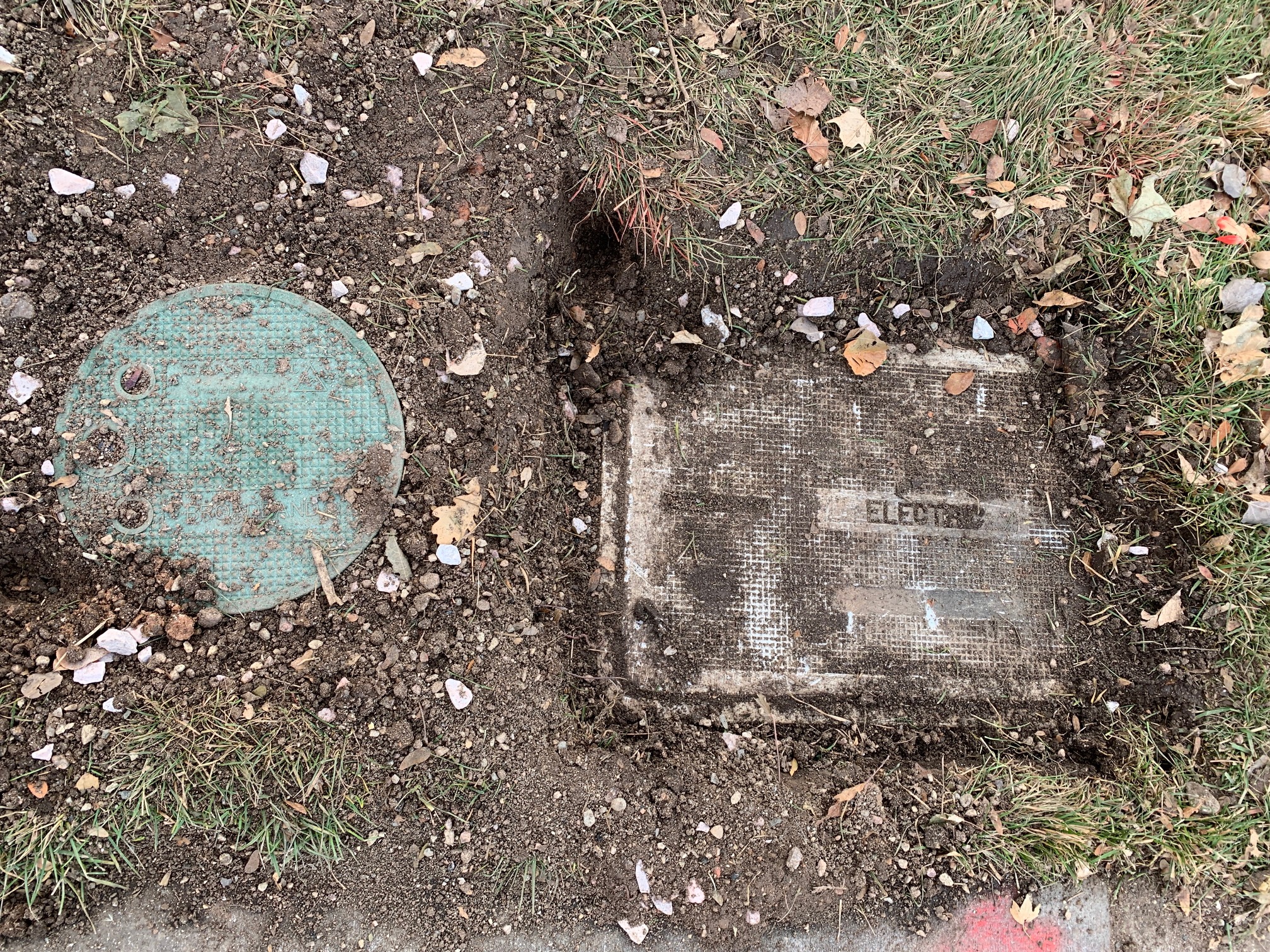
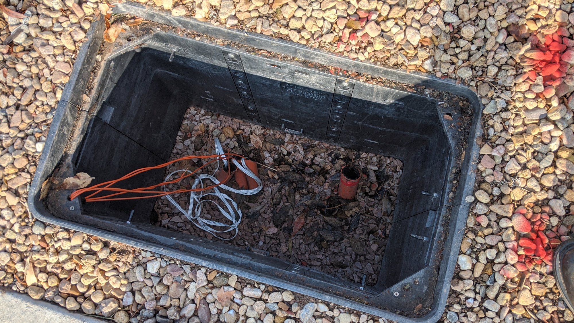
The inside of a splice vault.
Finally for today’s update, I walked around the neighborhood to see what else was happening. They ran a few more short runs of conduit across other streets and installed a few more splice vaults. Above is a photograph of the inside of a splice vault that was being installed late Friday. That’s probably an electrical line running through the vault on the left. They’ve also been installing splice vaults on Saturdays lately.
November 19 – Major Push to Finish Vaults and Flower Pots
A Connexion contractor installs a flowerpot in my front yard. Image courtesy one of my neighbors.
Last week, the electric utilities were marked again and the conduit previously placed in my yard was moved closer to the curb. This week saw another round of gas locates on Monday and a major push to finish the vaults and flower pots throughout the current construction area in the neighborhood on Tuesday.
The finished result. Image courtesy one of my neighbors.
As a result, all the conduit, flower pots, and vaults are installed on Michener, Mercy, Dixon Creek, Blue Leaf and the nearby cul-de-sacs. The construction crews have moved north to Zendt, Garrett, McKeag, and Seccomb now. The area northwest of Yorkshire has been complete for a while. The next step will be for Connexion crews to pull or blow fiber through the conduit and into all the vaults and flower pots.
As a side note, I heard that Connexion distributed service available flyers around November 13 in the Evergreen neighborhood on the northeast side of town. Evergreen will be the second neighborhood to have service. The Greenbrier neighborhood, also on the northeast side of town, was the first.
November 22 – Tracer Wire Installation
Today AEG crews pulled conductive copper tracer wires and replacement pull tape through the recently completed conduit in my neighborhood. The tracer wires will allow utility crews to locate the conduit anytime any digging or other underground work needs to be done in the future.
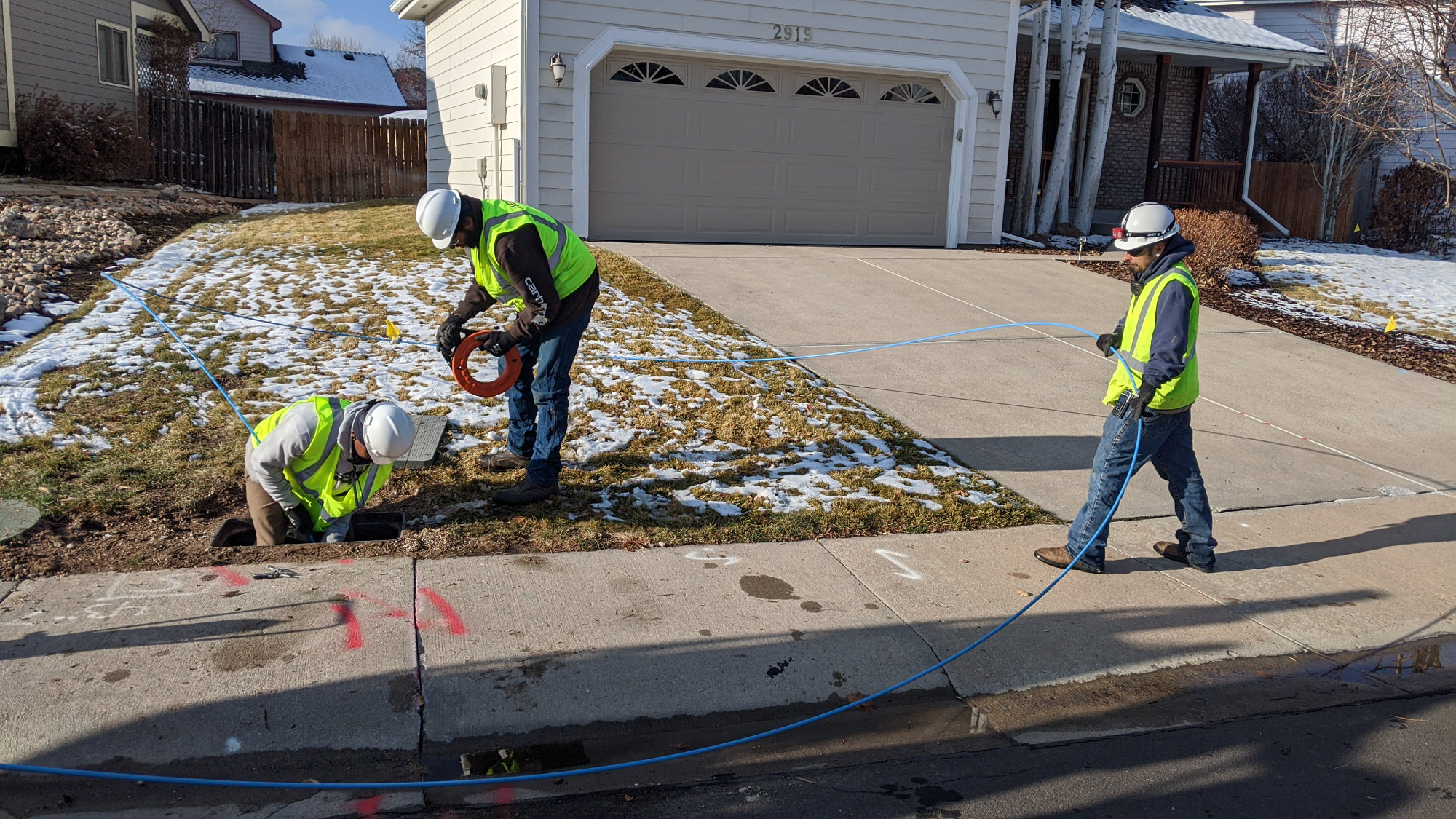
AEG technicians push a big blue flexible plastic rod down a length of conduit to locate the other end of it. They can also use an ordinary fish tape like the orange one here for shorter conduit runs.
Crews start work at a vault containing multiple pieces of conduit then determine where each piece of conduit in the vault leads using a flexible blue plastic rod or an ordinary fish tape as shown in the photo above.
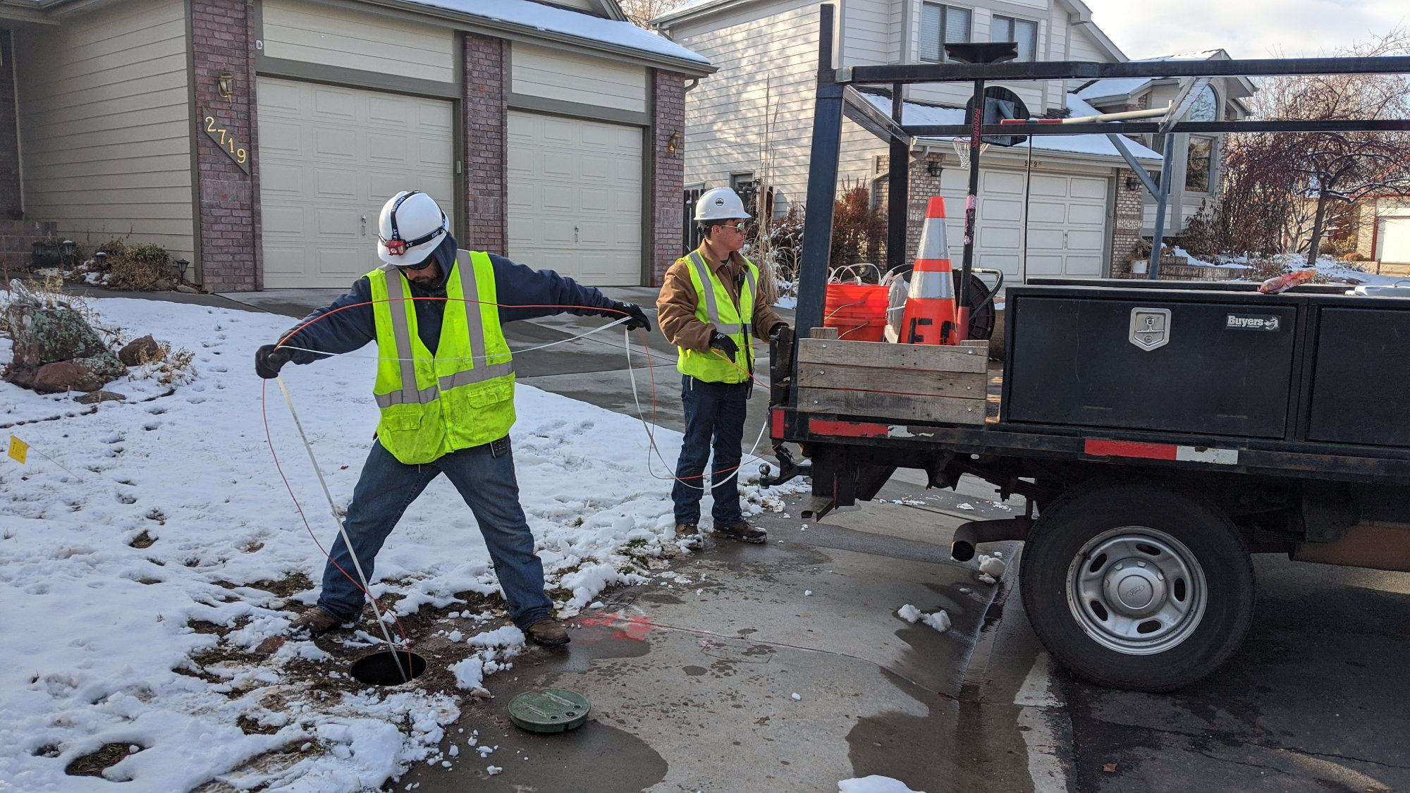
AEG technicians on the other end of the conduit pull the existing pull tape while the pictured technicians feed in the orange tracer wire and a replacement pull tape.
Once the far end of the conduit is located, a team drives a spool of copper wire with orange insulation and a spool of pull tape to that location. There technicians tie the tracer wire and pull tape to the piece of pull tape that came preinstalled in the conduit. The technicians back at the vault then pull the tape while the technicians at the far end feed the tracer wire and replacement pull tape into the conduit as shown in the photo above.
A vault with multiple lengths of conduit, their tracer wires, and replacement pull tapes.
Once they’re done, the vault will have a tracer wire and pull tape for each piece of conduit. In the photo above, there’s still one piece of conduit that needs a tracer wire and pull tape. Finally all the tracer wires are bonded together electrically and the vault lids are secured with screws.
In the future when underground work needs to be performed, a utility locator will open a vault cover and attach a radio transmitter to the copper wire. The utility locator will then locate and mark the path of the tracer wire, conduit, and fiber underground using a radio receiver. Since the conduit and fiber do not conduct electricity or radio frequencies, there would be no way to attach a transmitter and do the locates without the conductive copper tracer wire running inside the conduit.
December 18, 2019 – Fiber!
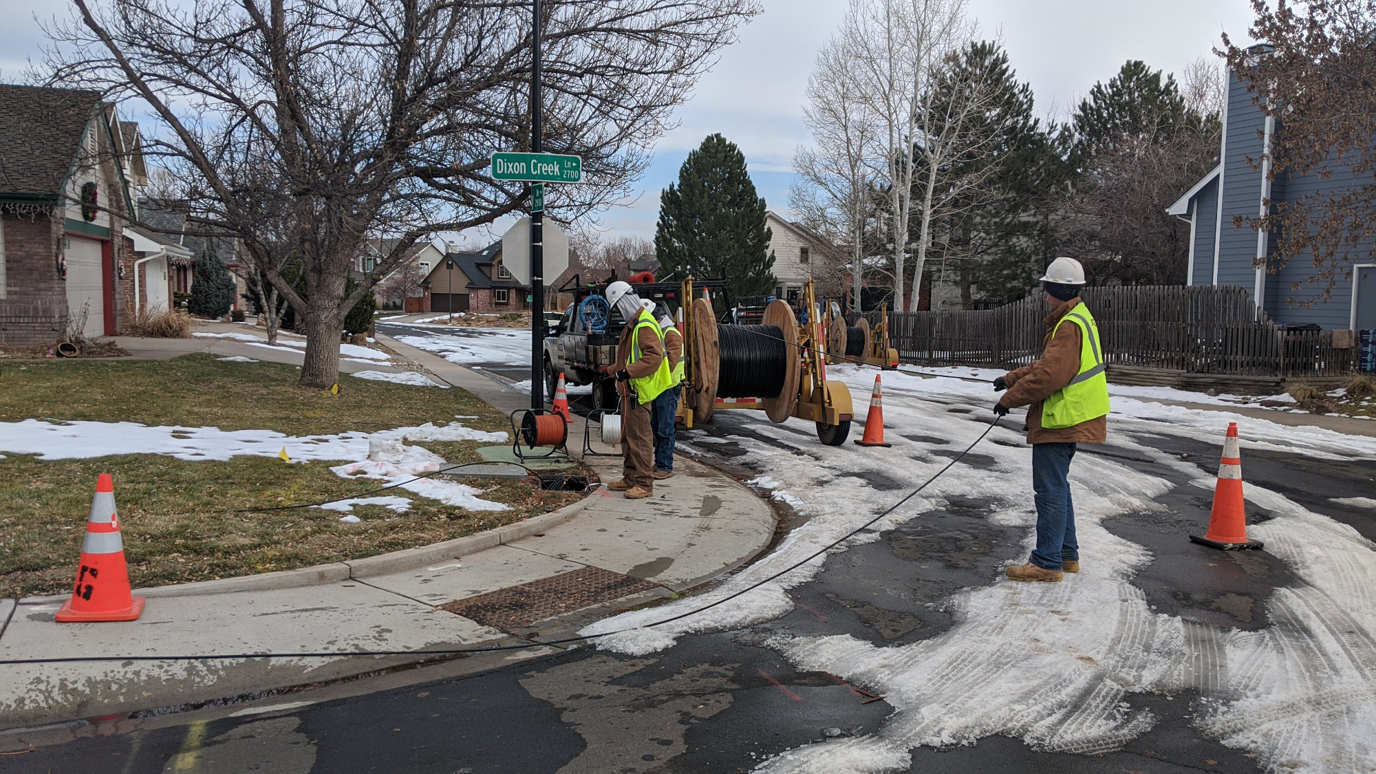
AEG techs pulled fiber in near freezing temperatures while trying not to slip on the remnants of 20 inches of snow! They pulled a 144 fiber cable to here. Now some 96 and 24 fiber cables branching off deeper into the neighborhood. This is one corner away from me.
Early last week crews pulled feeder fibers into the splice vaults. The main feeder fiber for this part of our neighorhood came in from Overland Trail around Skimmerhorn and contains 144 fibers. This cable was pulled to the intersection in the photo above. From there several 24 and 96 fiber cables were pulled to other vaults in the neighborhood. Other crews will come along later to splice these fibers together, install the optical splitters, and run fiber to the flower pots.

Hubbell Wiring Device’s 03305005 junior pulling grip with flexible eye. https://www.hubbell.com/hubbell/en/Products/Electrical-Electronic/WireCableHose-Management/Wire-Mesh-Grips/Pulling-Grips/03305005/p/1673544
To pull the cable, crews put an end of the cable into a pulling grip like the one in the photo above. Next they tie the eye of the grip to the pull tape already in the conduit. Pulling on the eye of the grip causes the wire mesh to tighten around the cable. A person on the far end of the conduit then pulls on the pull tape while the crews on the near end unroll the fiber from the spool and feed the cable into the conduit. Crews leave enough fiber spooled up in the vaults that the fiber can be pulled out of the ground and into a truck to make any necessary splices between the different fiber cables in the vault.

A close up of some Fortex AT-3CE12YT-024 24 fiber cable. All the cables are labeled Fort Collins Connexion.
The photo above shows a close up of some 24 fiber cable on the spool. The fiber cable is labeled with the name of the network, Fort Collins Connexion, and the manufacturer’s model number, AT-3CE12YT-024. From the model number, I was able to locate the data sheet (PDF) for the fiber.
This particular cable is an unarmored, all-dielectric cable. Armored cable has a protective metal sheath just inside the outer jacket. Since this cable does not have the metal sheath, it’s better suited for conduit installations like in Fort Collins and lashed aerial installations than direct burial. All-dielectric means this cable has zero parts that conduct electricity. As a result, a separate tracer wire must be run in the conduit with the cable to locate it once it’s underground.
This cable has losses between 0.25 dB/km and 0.35 dB/km depending on the wavelength (color) of the light running through the fiber. A loss of 0.25 dB/km means that after 3280 feet, the light at the far end of the fiber will be 6% dimmer than it was at the source. For comparison, a high-perfofmance undersea fiber optic cable may have a loss as low as 0.14 dB/km or a bit over 3% over the same distance.
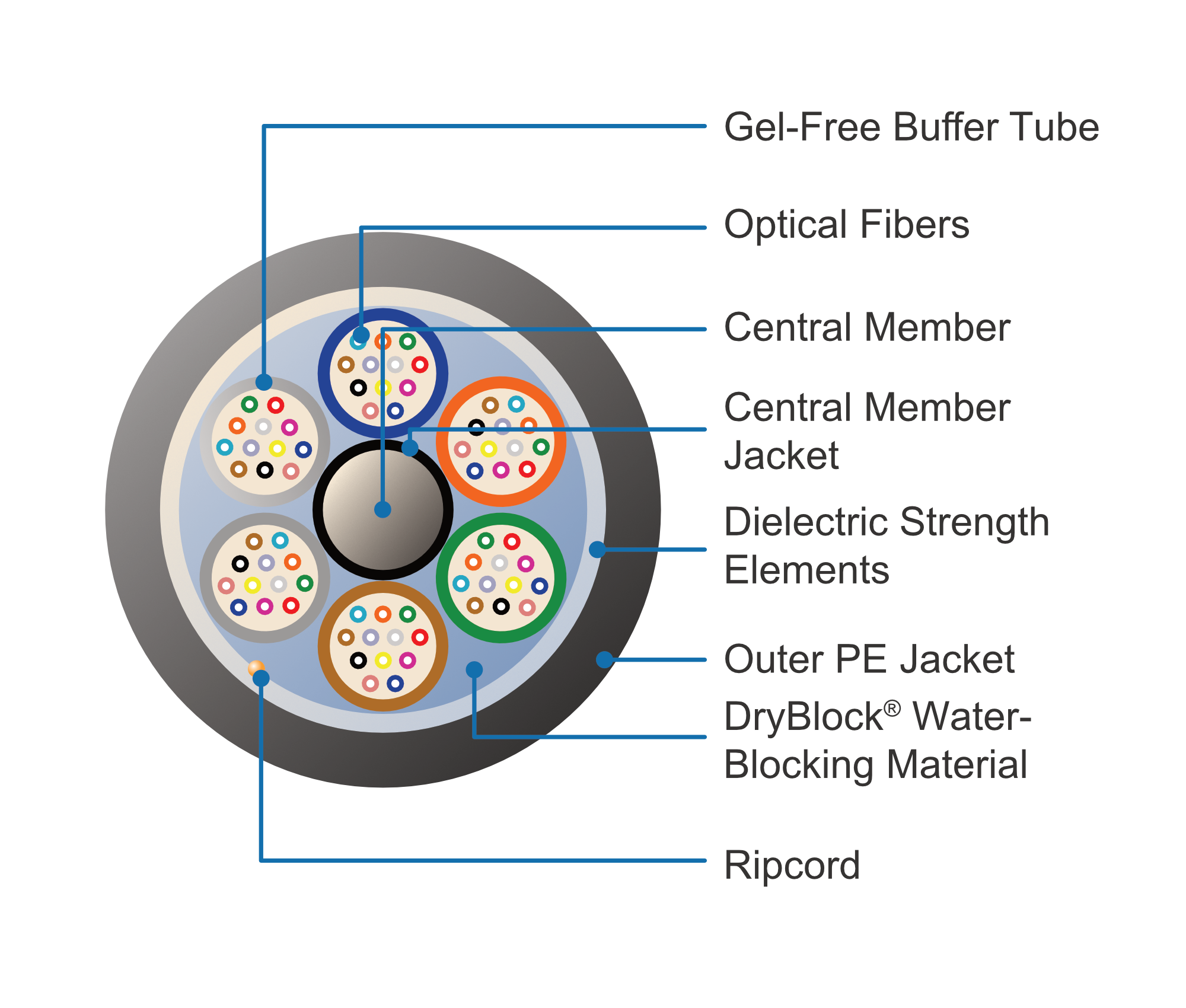
Diagram of the components inside a 72 fiber cable from the cable datasheet. https://fiber-optic-catalog.ofsoptics.com/Asset/Fortex-DT-Single-Jacket-145-web.pdf
The diagram above is from the data sheet for the cable. It depicts a 72 fiber cable. Twelve color coded strands of fiber are placed in six color coded buffer tubes. These surround an inner central member that provides rigidity to the cable and keeps the fibers and buffer tubes from folding in on themselves. The buffer tubes and central member are surrounded by strength members. These provide tensile strength to allow the cable to be pulled in conduit without breaking the glass fibers. The final outside layer is a polyethylene jacket that protects the cable against moisture. There’s also a ripcord to make separating the jacket from the inner members easier.
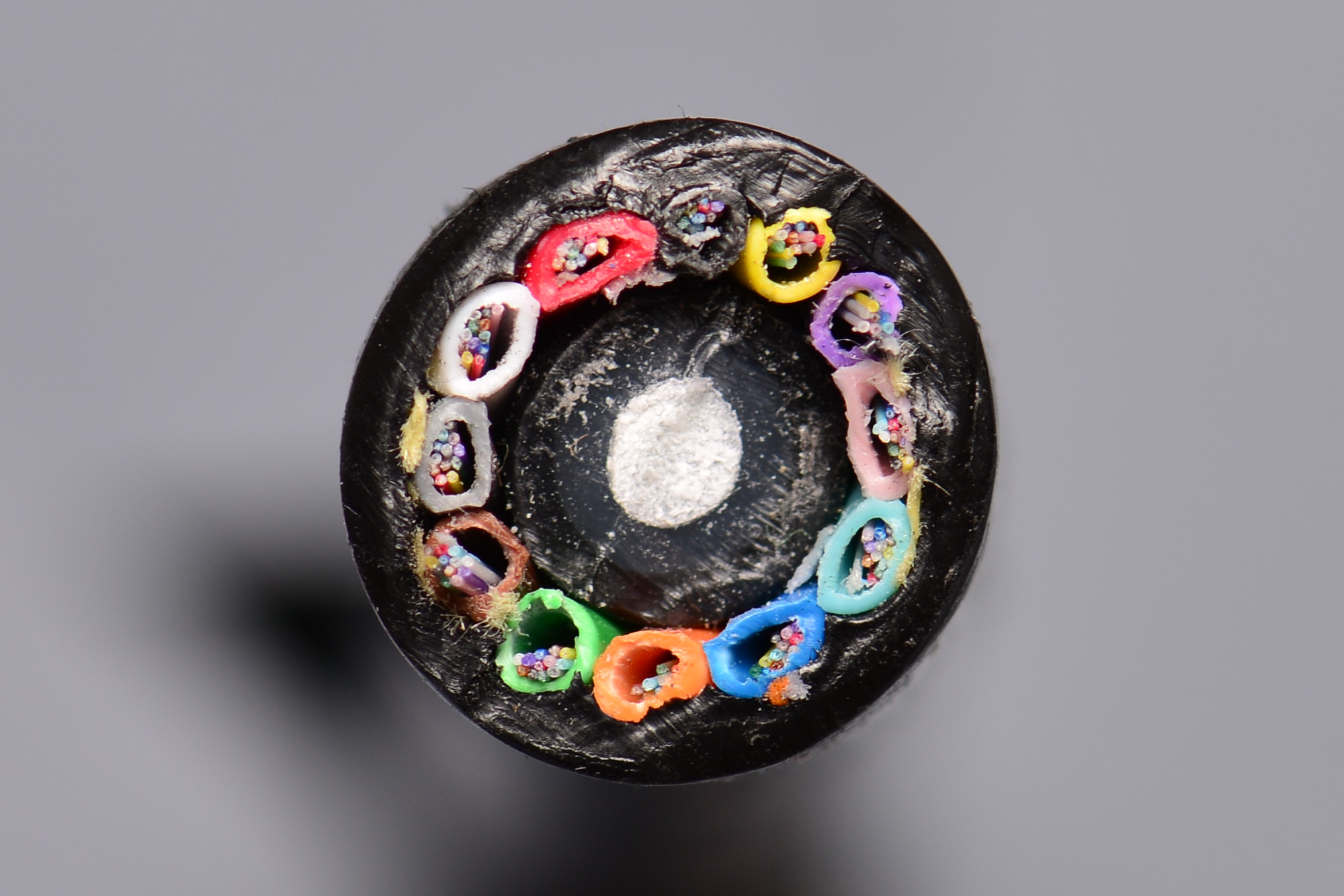
Cross section of a 144 fiber cable. Each of the twelve large colored jackets contains twelve individual fibers.
Here’s a cross section of an actual 144 fiber cable like the ones that are used for Fort Collins Connexion. This cable contains twelve buffer tubes and each buffer tube contains twelve fibers. There’s quite a bit of space around the fibers inside the buffer tubes and the fibers can move freely inside them. The inner core is the white/gray/black material in the center of the cross section. The outer strength members are the small yellow fabric-like strands spaced around the outside of the fiber tunes. The orange and white strand just below the blue tube is the ripcord. The black outer wall is the polyethylene jacket.
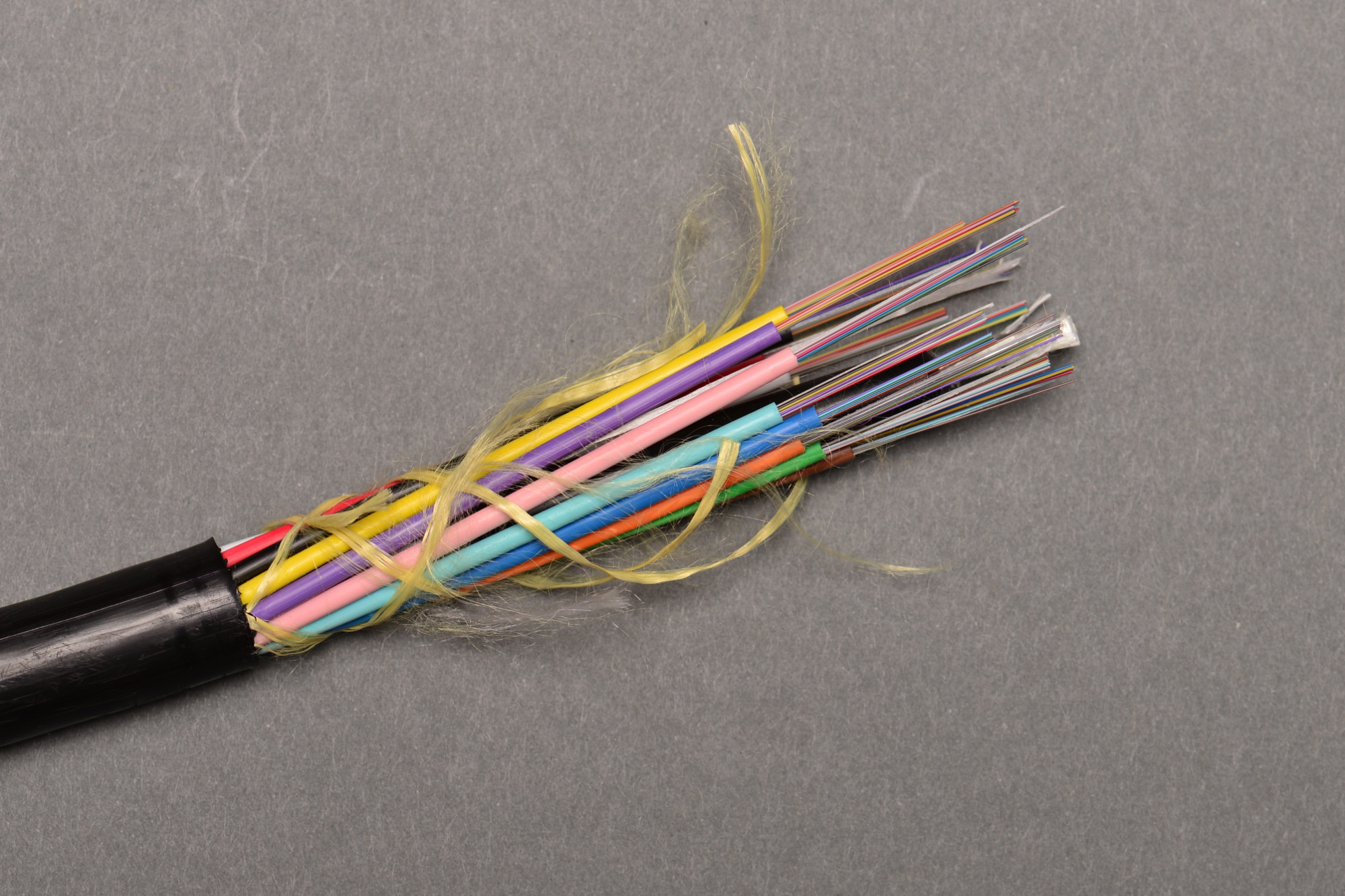
A 144 fiber cable stripped to show the individual fibers. Each of the slimmest colored jackets contains a single fiber. These are bundle into groups of 12 and placed inside a larger colored jacket.
The photo above shows what the fiber optic cable looks like with the outer black polyethylene jacket removed and about an inch of each buffer tube removed. One fiber is inside each of the smallest colored jackets and there’s twelve fibers inside each colored buffer tube.
End of Part Two – The Journey Continues in Part Three
This second post is getting a bit lengthy now too so I created a third post to document future events. The first entry in part three takes a look at the installation of service at my friend Colin’s house in the northeast part of Fort Collins. Once that’s done, we’ll look at the fiber splicing operations back in my own neighborhood.