
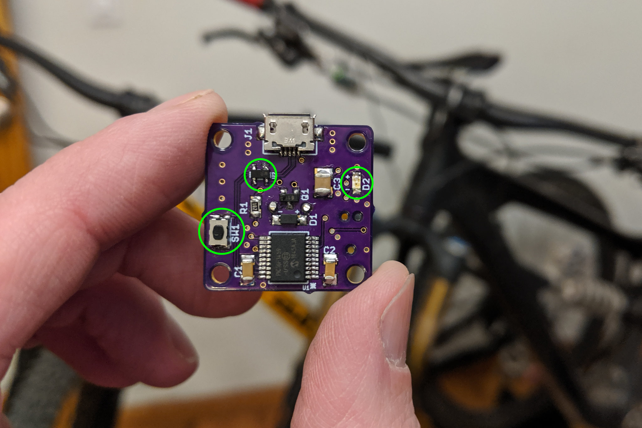
Some new additions to the annoying caps lock warning buzzer (circled in green).
In my first post on the Annoying CAPS LOCK Warning Buzzer, I concluded with a list of future improvements to make to the project. Those updates are now implemented and the Annoying CAPS LOCK Warning Buzzer is more robust than ever. Read on to find out more about the improvements.
Goals for Improvements
The list of new features and improvements is pretty short:
- Include a ground plane on both sides of the board. Route +5V as traces.
- Add some basic ESD protection.
- Add a button and LED to use with a USB bootloader and firmware update utility to apply firmware updates.
- Make the button and LED accessible without disassembling the buzzer.
Let’s run through each of the improvements separately.
Ground Plane
On the old board, the ground plane was on the component / top layer with a +5V plane on the bottom. This wasn’t causing any problems (that I know of) but the ground plane was broken by up all the pads for the surface-mount components. In the new version, both sides of the board contain a filled ground plane with lots of vias to bond the two ground planes to each other. The +5V is now routed as traces on the bottom of the board.
In theory this will reduce noise on the board and improve the electromagnetic compatibility of the board. One day I’ll have to bring both the old board and new board to work, find a spectrum analyzer and EMC probe set, and learn to make some EMC measurements. In the meantime, at least I didn’t break anything with the ground plane changes.
ESD Protection
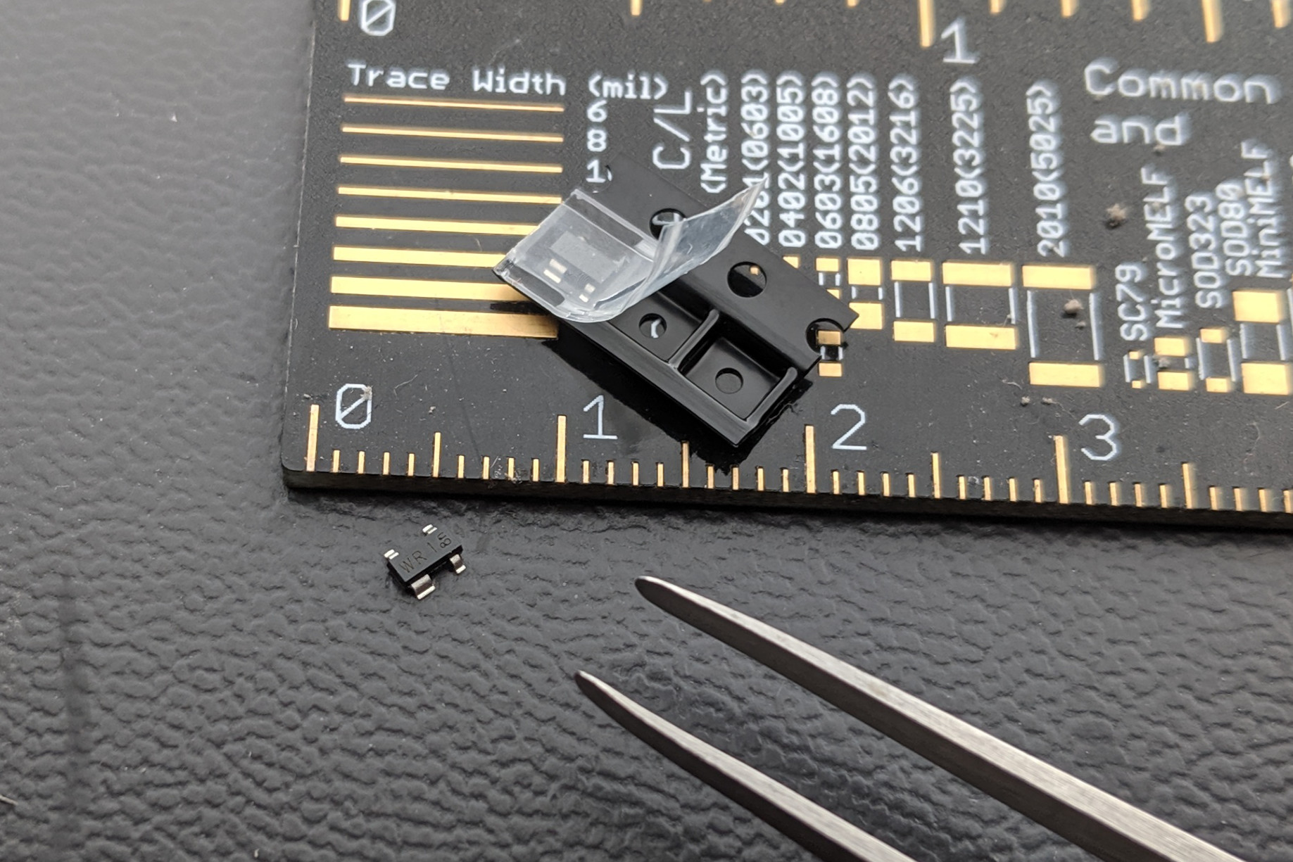
That’s the Nexperia PRTR5V0U2X ESD protection diode below the five millimeter mark on my Adafruit PCB ruler. It’s small but not any worse than an SOT-23 transistor to hand solder.
The second change was to add some basic ESD protection using a Nexperia PRTR5V0U2X ultra-low capacitance double rail-to-rail ESD protection diode. This single device protects both USB data lines even in the absence of a supply voltage. The device needs to be located as close as possible to the USB connector and be very-well connected to the ground plane of the board.
Button and LED and Resistor
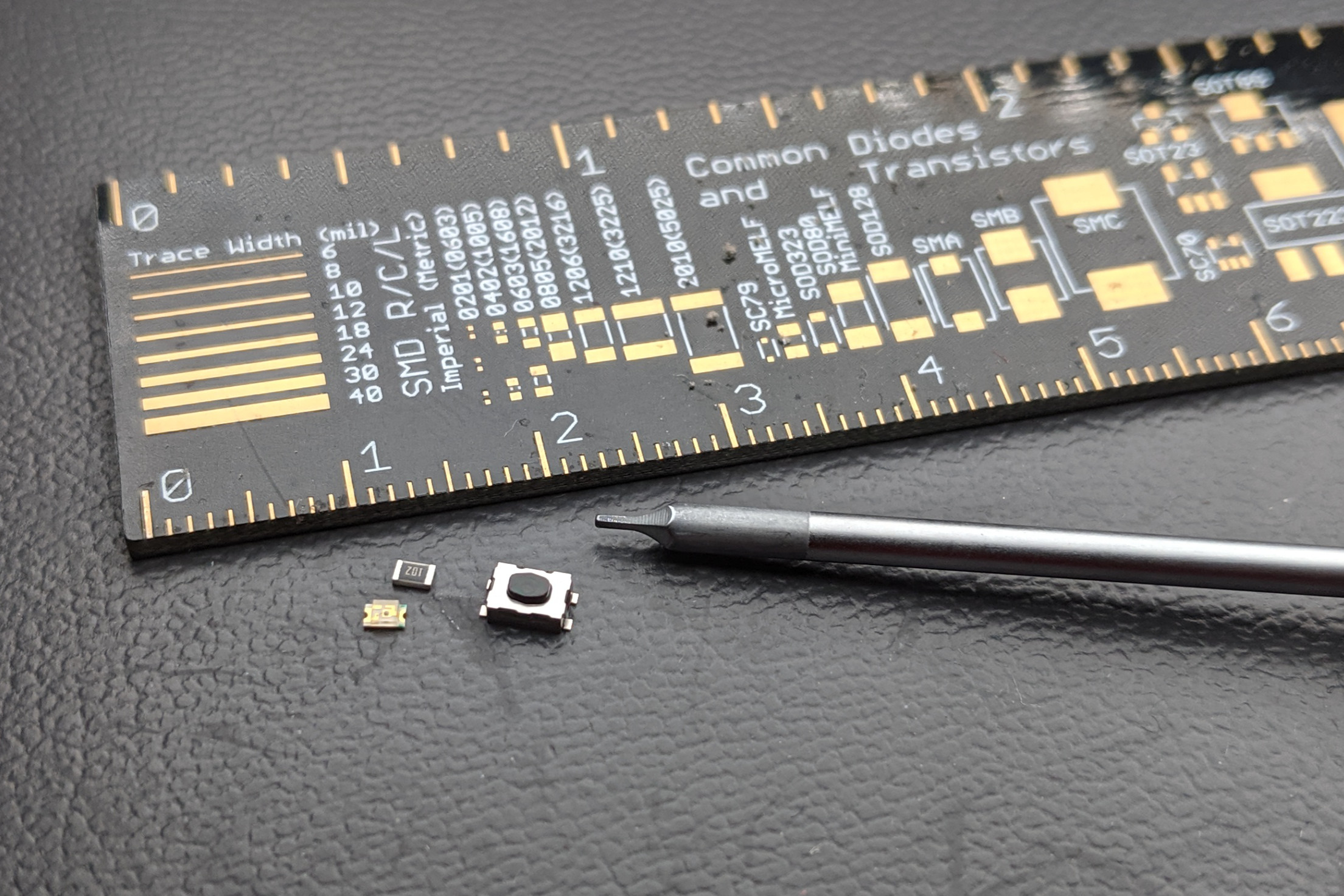
A KMR2 tactile switch, an 0805 1k resistor, and an 0805 orange LED.
The next improvement was to enable the use of the Microchip Library for Applications (MLA) USB bootloader to update the firmware on the Annoying CAPS LOCK Warning Buzzer. At boot time, the USB MLA bootloader checks a pushbutton switch. If the switch is pushed, the bootloader goes into a mode where the application firmware can be updated over USB. If the switch is not pressed, the USB MLA bootloader boots directly into the application firmware.
I needed a small pushbutton switch to use with the bootloader. I searched Digi-Key and Mouser looking for an SMD tactile switch. I found lots of candidates. I finally settled on a C&K Switches KMR211NGLFS tactile switch. If you have an Adafruit Feather M0 board, this is very similar to the reset switch on that board.
The MLA USB bootloader can also blink an LED to indicate the state of the bootloader. I decided to take advantage of this feature. I selected a Dialight 599-0130-007F 0805 SMD orange LED. Any color would work but orange is somewhat different than the typical red or green LEDs on projects. Finally, I needed a current limiting resistor for the LED. I went with a small 1k 5% 0805 SMD resistor.
Enclosure Modifications

The updated enclosure. Two two millimeter diameter holes on the bottom allow access to the tactile switch and LED.
To make the pushbutton and LED accessible without having to disassemble the warning buzzer, I added two 2 mm holes to the bottom of the enclosure. When the board is placed in the enclosure, one hole is directly over the pushbutton and the other hole is directly over the LED. The pushbutton can be pushed via a small screwdriver or paper clip. The LED light is visible by turning the buzzer upside down.
Updated Schematic
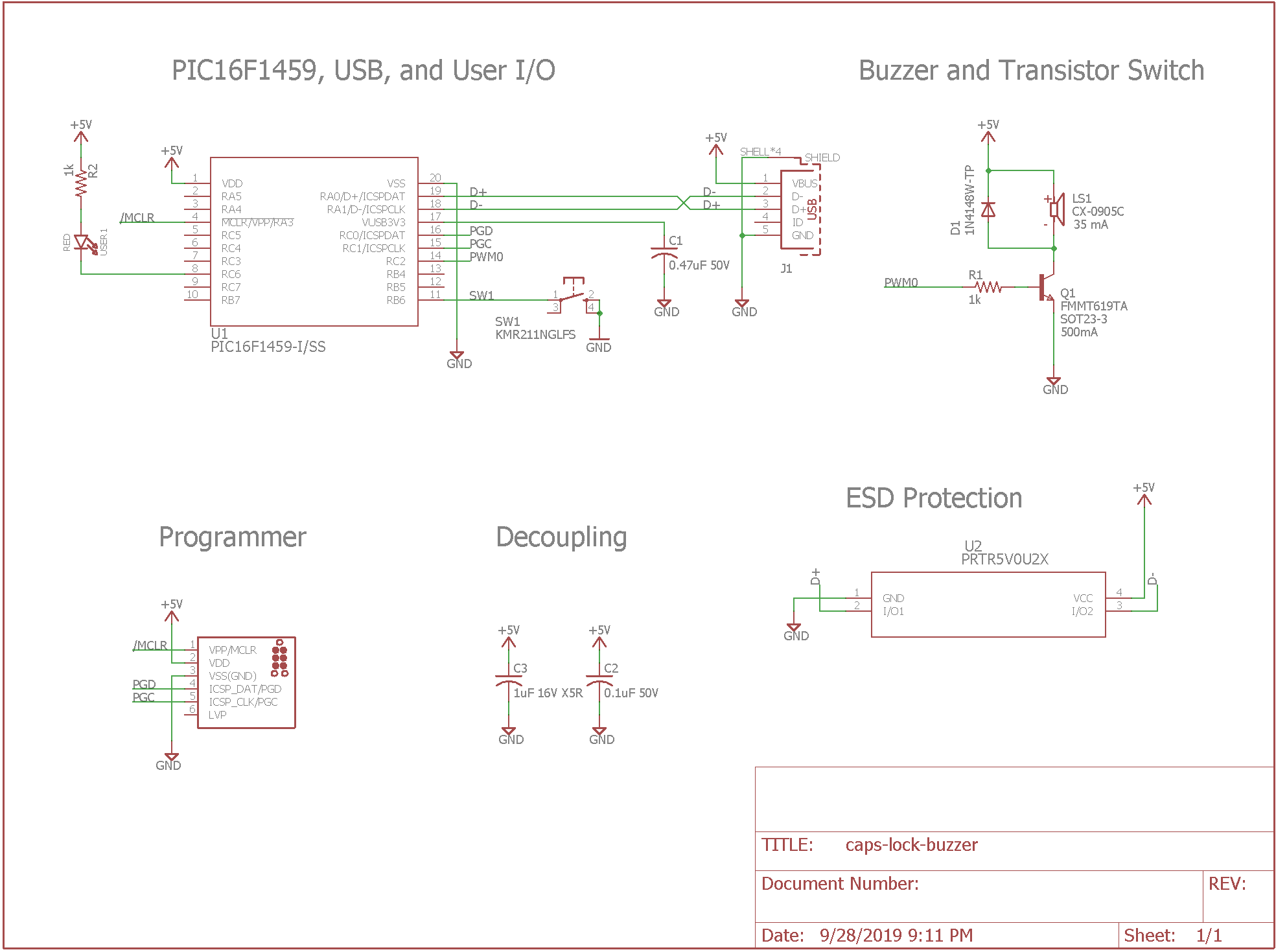
Updated schematic. The U2, SW1, R2, and USER1 LED are new to this version of the design.
The schematic above show the updates made for the second version of the warning buzzer. U2, SW1, R2, and the USER1 LED are new to this version of the design.
Updated Boards
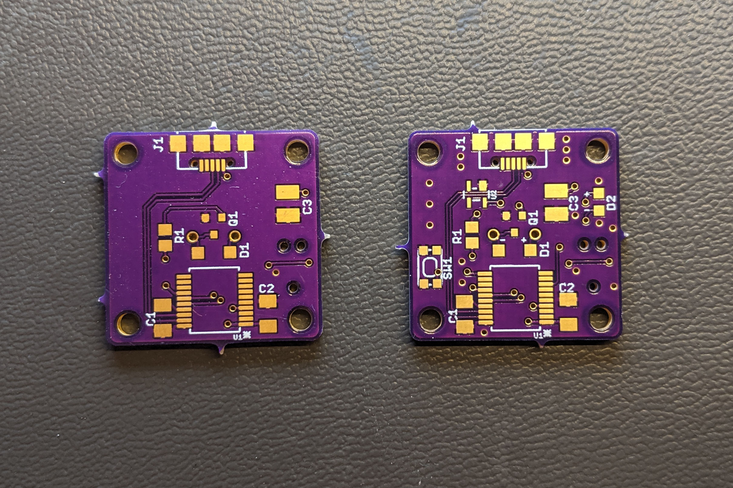
Old board on the left. New board on the right.
The photo above shows the old version of the design on the left and the new version of the design on the right. Most of components and traces are in the same place. The current limiting resistor for LED D2 / USER1 is on the reverse side of the board. Notice the many vias on the new design of the board. These vias connect the ground planes on each side of the board together.
Updated Enclosure
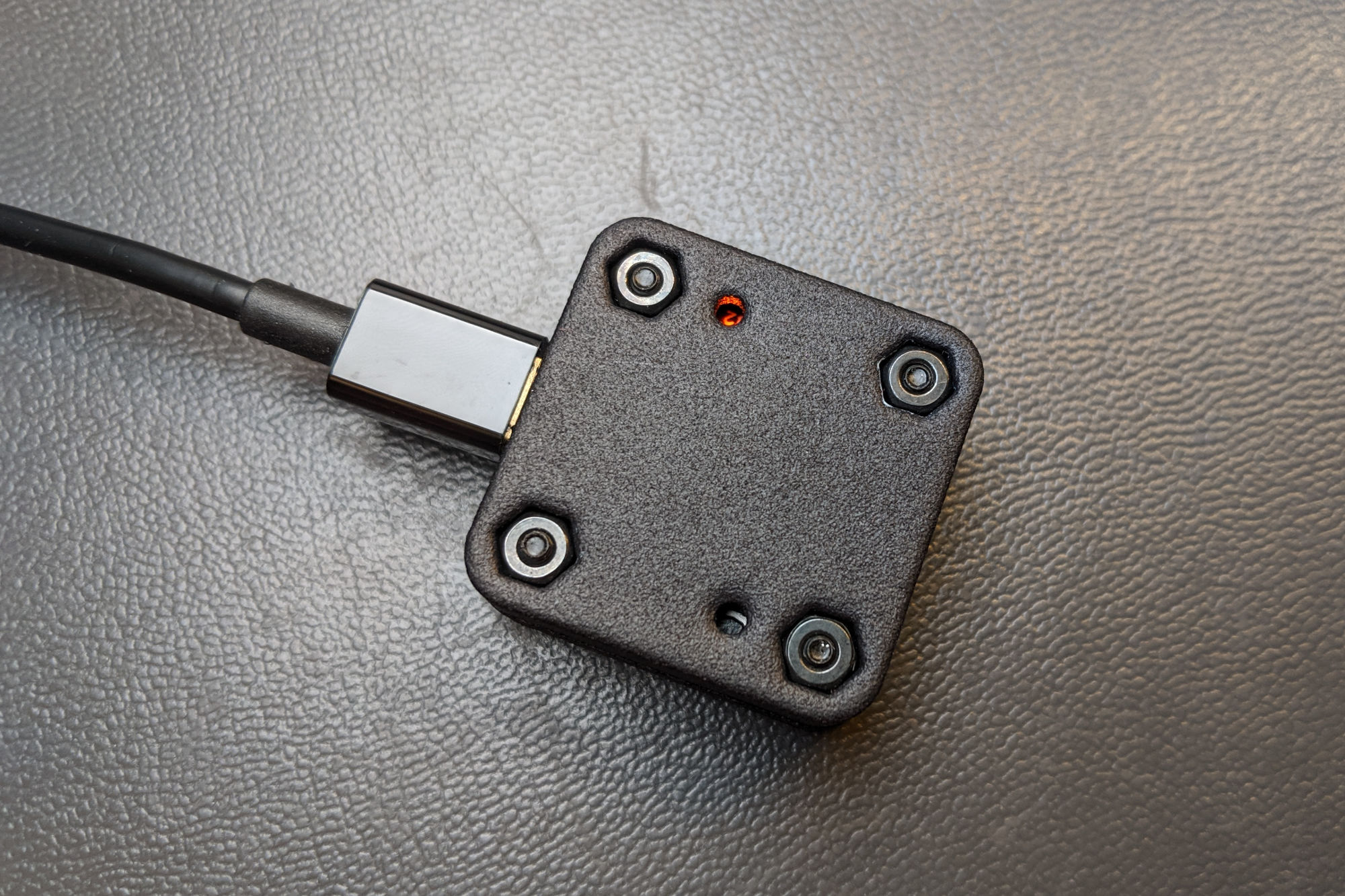
The bottom of the annoying CAPS LOCK warning buzzer with the modifications to expose the LED and pushbutton.
The bottom of the updated enclosure is shown in the above photo. The hole with the orange glow is the LED. The other hole is for accessing the pushbutton swtich.
Updated BOM
The components that are new to the second version of the design are listed in the table below. You’ll also need a second 0805 1k 5% resistor.
| Line # | Mfr. # | Manufacturer | Description | Order Qty. | Price (USD) |
| 1 | KMR211NGLFS | C&K Switches | Tactile Switch | 1 | $0.52 |
| 2 | PRTR5V0U2X,215 | Nexperia | 5.5V ESD Protection Diodes | 1 | $0.51 |
| 3 | 599-0130-007F | Dialight | 0805 Orange LED | 1 | $0.26 |
Using the Bootloader
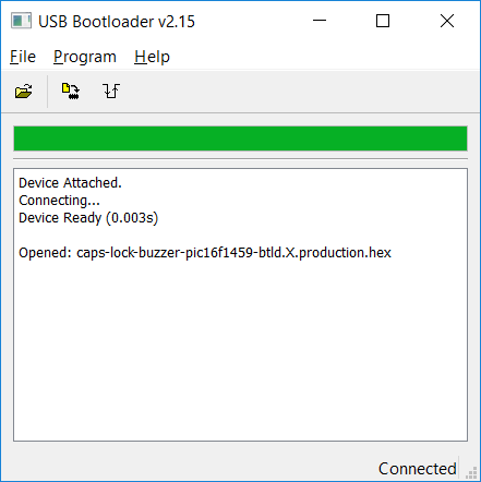
The main (and only) window of the Microchip Library for Applications USB Bootloader utility.
The MLA USB bootloader must be programmed using a PIC programmer such as the PICkit 4 or ICD 4 and the MPLAB X IDE or IPE. Once the bootloader is programmed, the bootloader can be used to update the application firmware. To update the firmware:
- Launch the MLA bootloader utility from the MLA install directory.
- Hold down the button using a paper clip or small screwdriver while plugging the warning buzzer into the USB port on the PC. Be sure to push on the pushbbutton; not the LED.
- Wait for the device attached and device ready messages as shown in the dialog box above.
- Click the open button in the GUI and select the .hex file from the dist directory inside the caps lock buzzer firmware directory.
- Click the program button to program the firmware into the warning buzzer.
- Click the reset button to reset the PIC and launch the application firmware. You can also unplug the warning buzzer then plug it back into the PC. Do not hold down the pushbutton this time.
- Test the firmware update by toggling the CAPS LOCK key on the keyboard to turn the warning buzzer off and on.
Design Files
All design files are in my caps-lock-buzzer repository on github.
The v2 schematic and board files:
The Fusion 360 Archive and STL files for the enclosure:
The updated software:
- PIC16F1459 Bootloader Project for use with this Hardware
- Caps Lock Buzzer Firmware for use with the Bootloader and this Hardware