
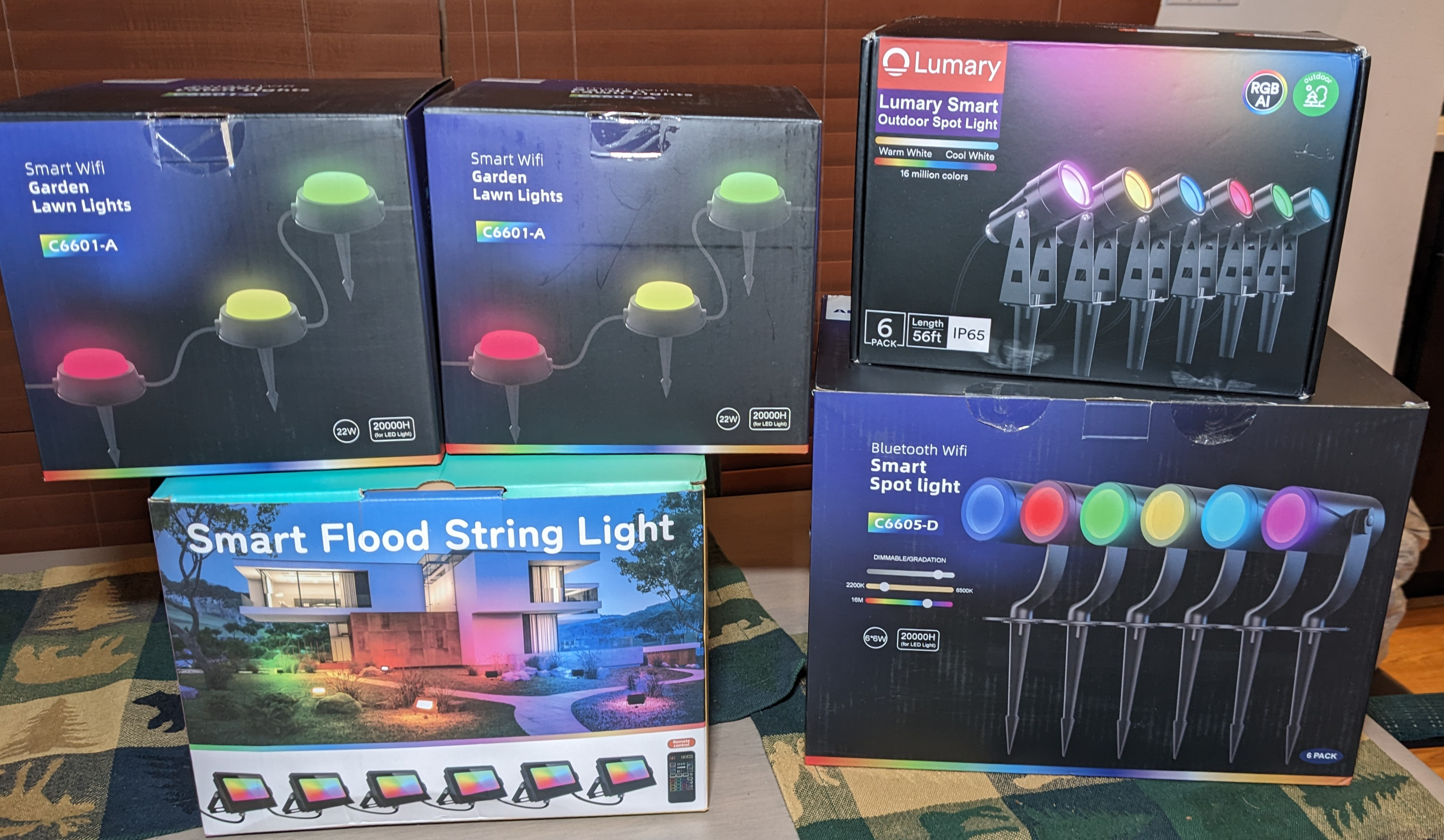
A Few of the Contenders
I’m always looking for new LED lights for Halloween, Christmas, and just general tinkering. My preference is for lights that can be modified to be controlled locally by WLED. Controlling the lights locally lets me integrate the lights into larger displays and coordinate the colors of all the connected lights using software like xLights. I recently purchased a few sets of random LED lights from 3rd party sellers on Amazon. Read on to find out which ones can be rewired to work with WLED and, by extension, xLights.
Disclaimer: Glen may earn compensation for sales from links on this post through affiliate programs.
My WLED Controller
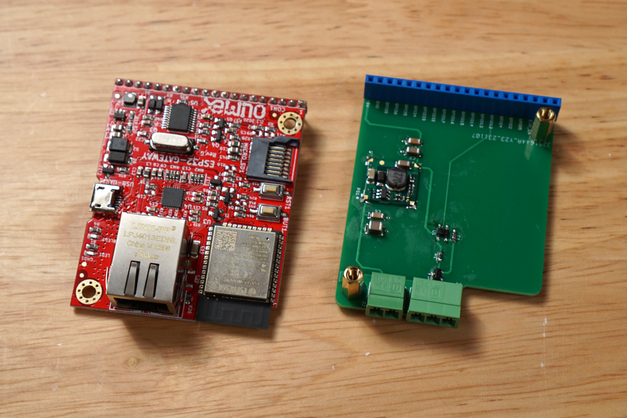
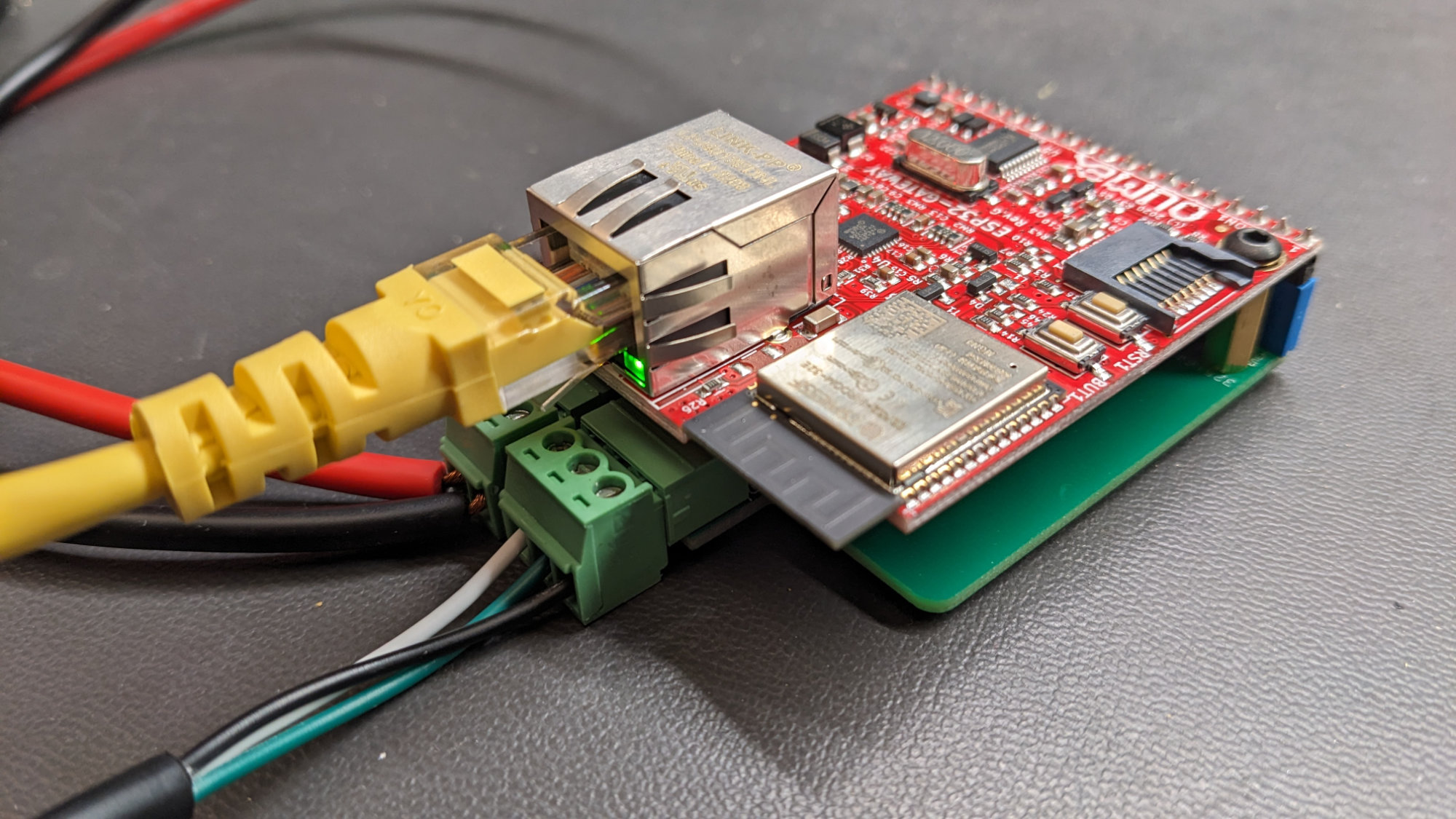
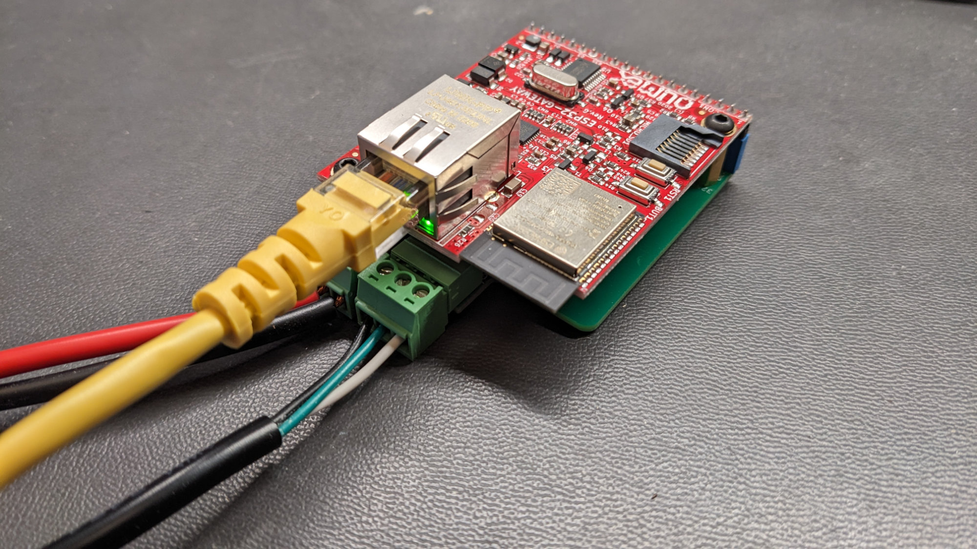
The Olimex ESP32-Gateway board and my interface board.
WLED runs on numerous platforms. I’m running WLED on an Olimex ESP32-Gateway board. I built a small interface board that connects the gateway board to the lights. This board connects to and mounts under the ESP32-Gateway using a 20 pin 0.1″ header. The small board has a two-pin connector for power from a power supply and a three-pin connector to supply power and data to the lights. Even though I’m using my own board, these lights could be controlled by any off-the-shelf WLED controller that supports the lights’ supply voltages.
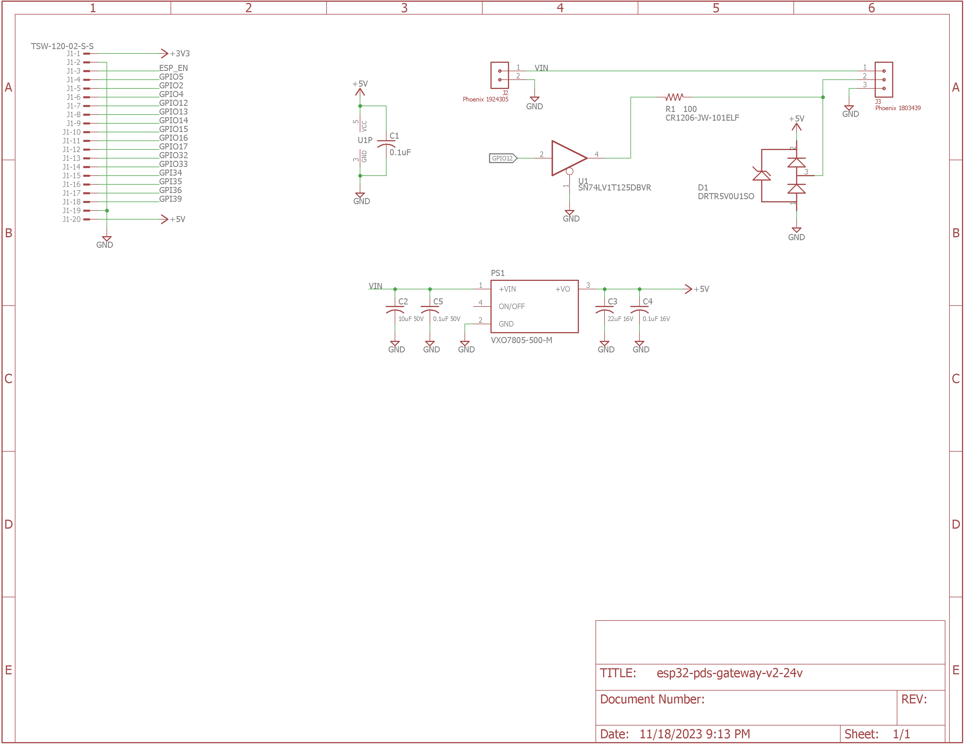
Schematic of my pixel driver board. It’s a few connectors, a 5 V power supply for the Olimex ESP32 Gateway board, and a 3.3 V to 5 V level shifter with series resistor and transient protector to drive the data line of the connected pixels from the ESP32.
As shown in the schematic above, the interface board contains a +5 V power supply for the gateway board and a +3.3 V to +5 V level translator for driving the pixels’ data line at +5 V from one of the gateway board’s +3.3 V output pins. The CUI DC/DC converter on the interface board supports a wide range of input voltages which allows the interface board to support both 12 V and 24 V pixels. There’s a series resistor and transient protector on the +5 V pixel data output to prevent problems.
Set #1: APPECK Smart WiFi Garden Lawn Lights, Set of 15
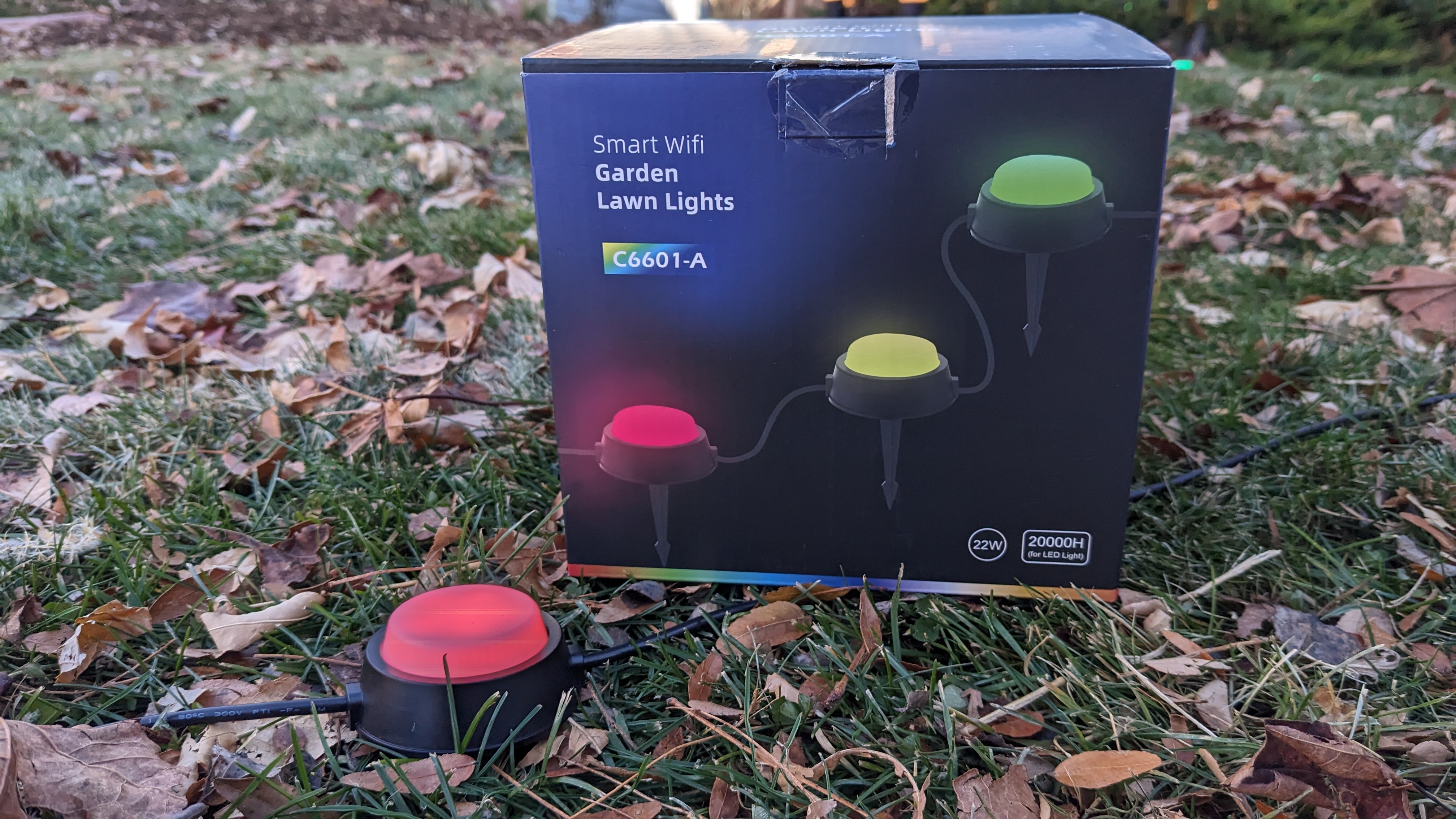
The empty box sitting next to one of the installed lights in my front yard.
First up are the 15 pack of APPECK Smart RGBICW Pathway Lights. I purchased two boxes of 15 lights at $36.99 each minus a $3.70 coupon for a total of $70.28 + tax.
Detailed Description

RGBW pixel with stake attached.
These are small RGB + WW dots that can be used to line the edge of a flower bed or garden. Each light is about 2″ in diameter and comes with a small plastic stake that screws to the back of the light and is used to secure the light in the ground. The distance between each light is about two feet.
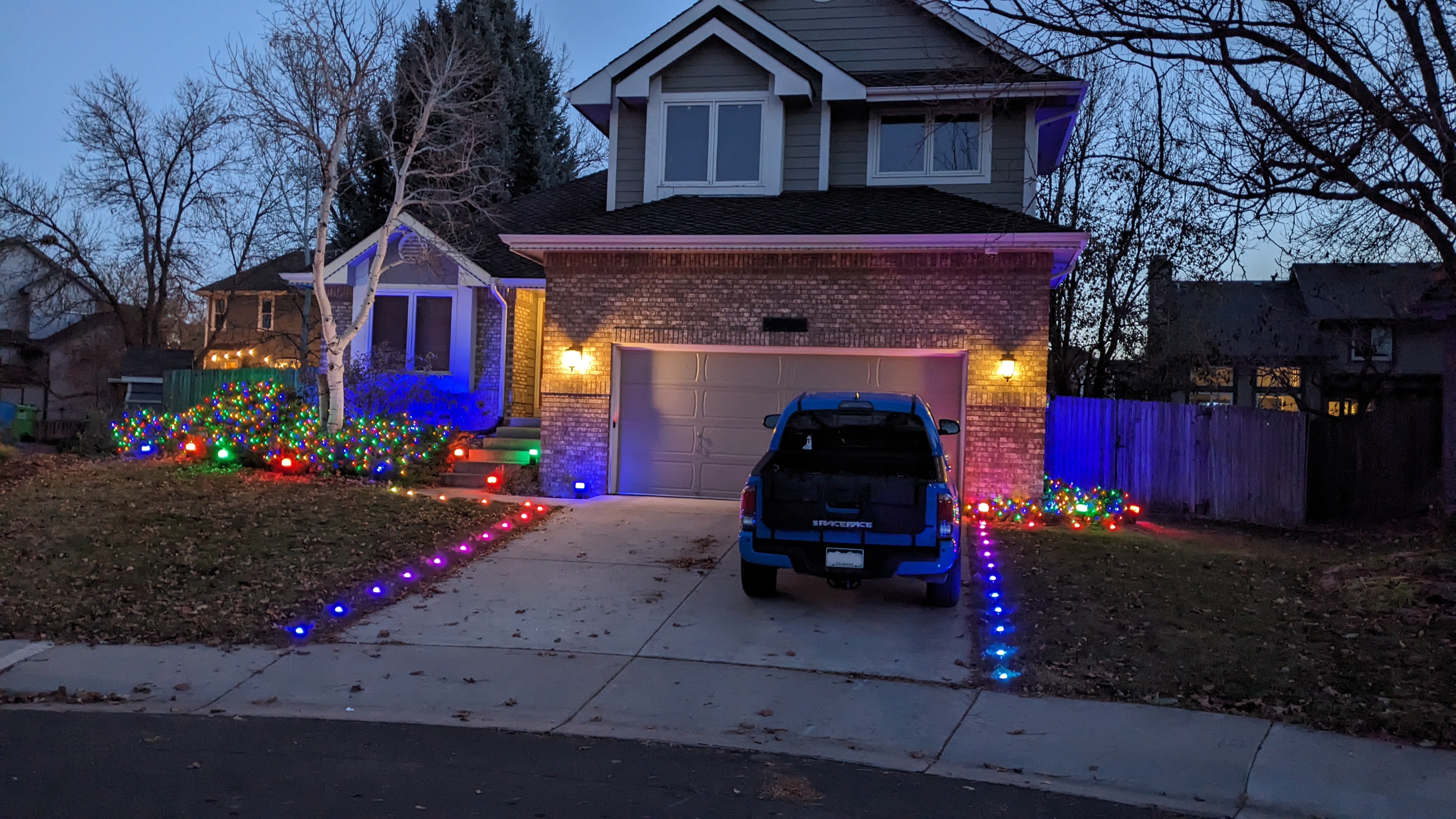
The lights placed in the grass on each side of the driveway.
I placed my two sets in the grass on each side of the driveway for the holidays.
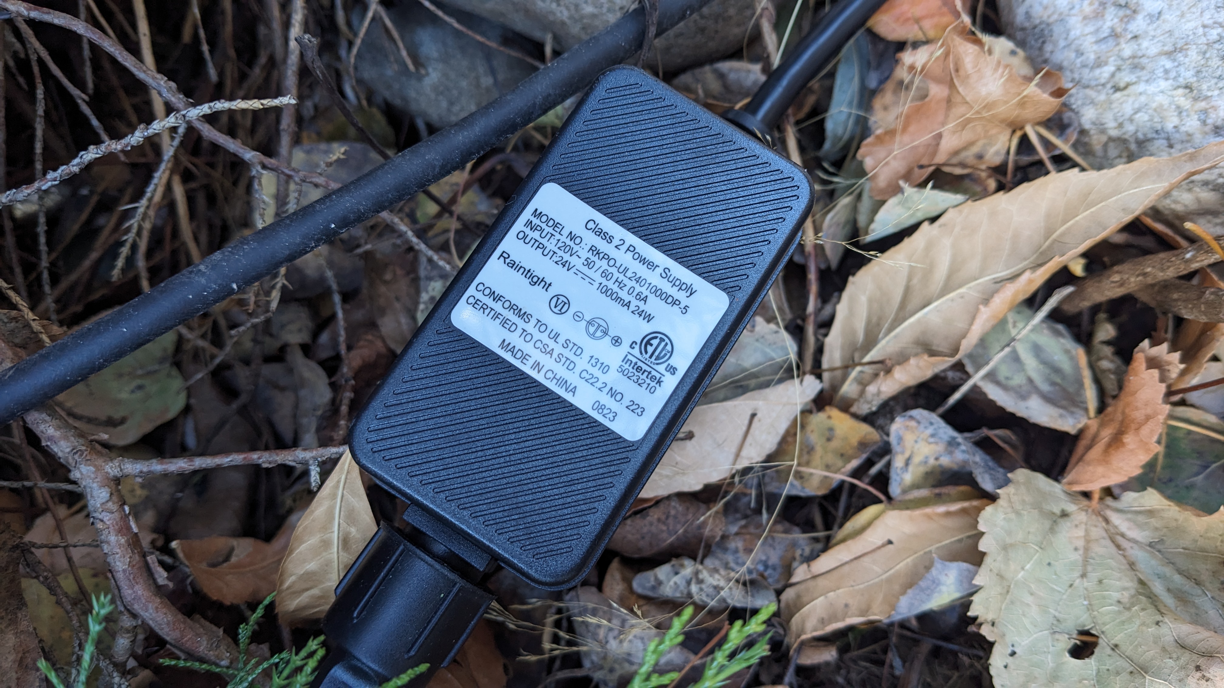
24 V 1 A 24 W power supply.
Each set consists of a power supply, a controller, and the 15 lights. The power supply plugs directly into the wall (or an extension cord as shown in the photo above) and is rated for 24 V at 1 A or 24 W.
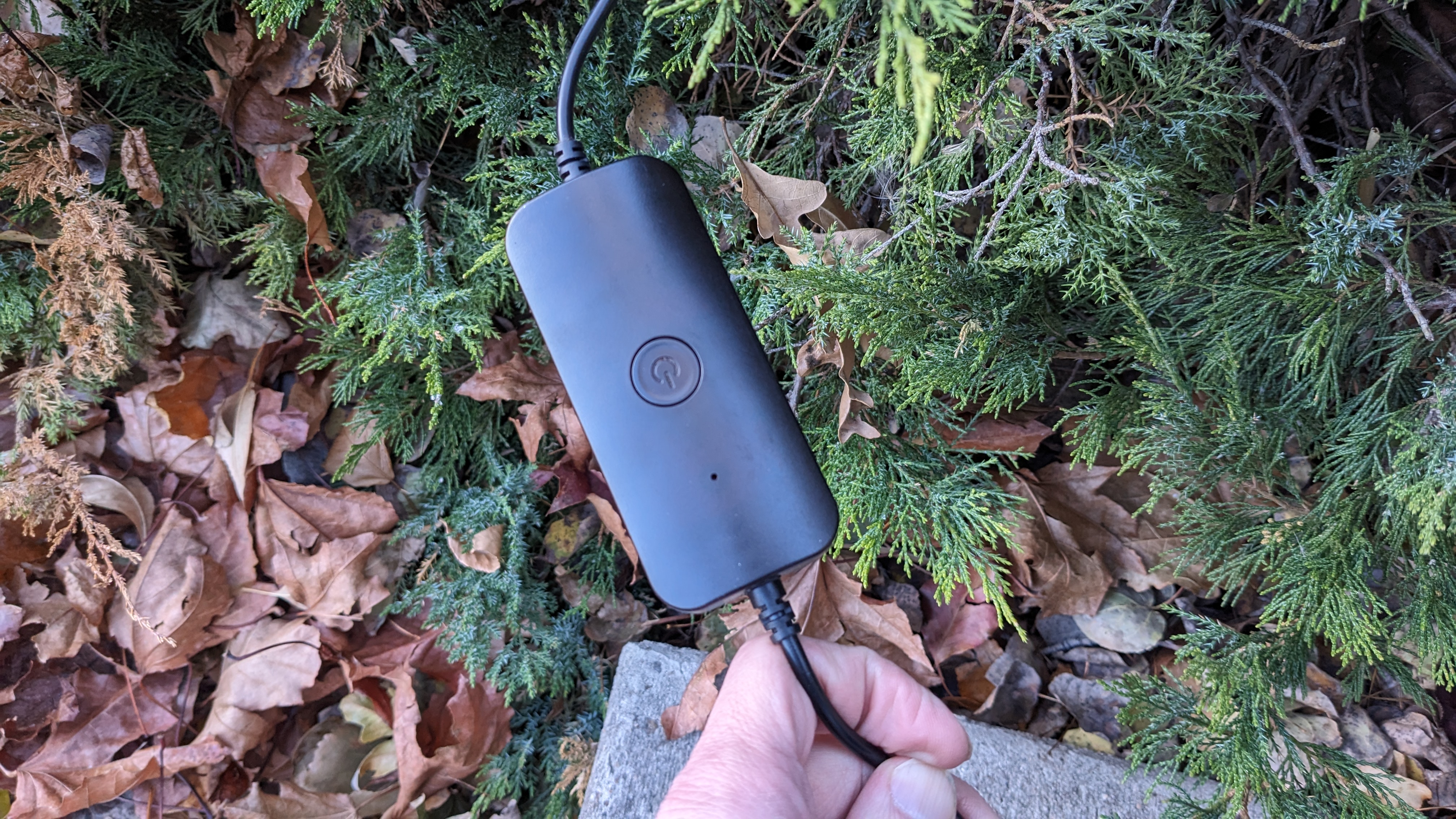
The power and light cables are permanently attached to the controller but can be unscrewed from the power supply and lights.
The controller is a small black plastic puck with a single button. The button is used to turn the light string on and off, change the light pattern, and enter pairing mode.
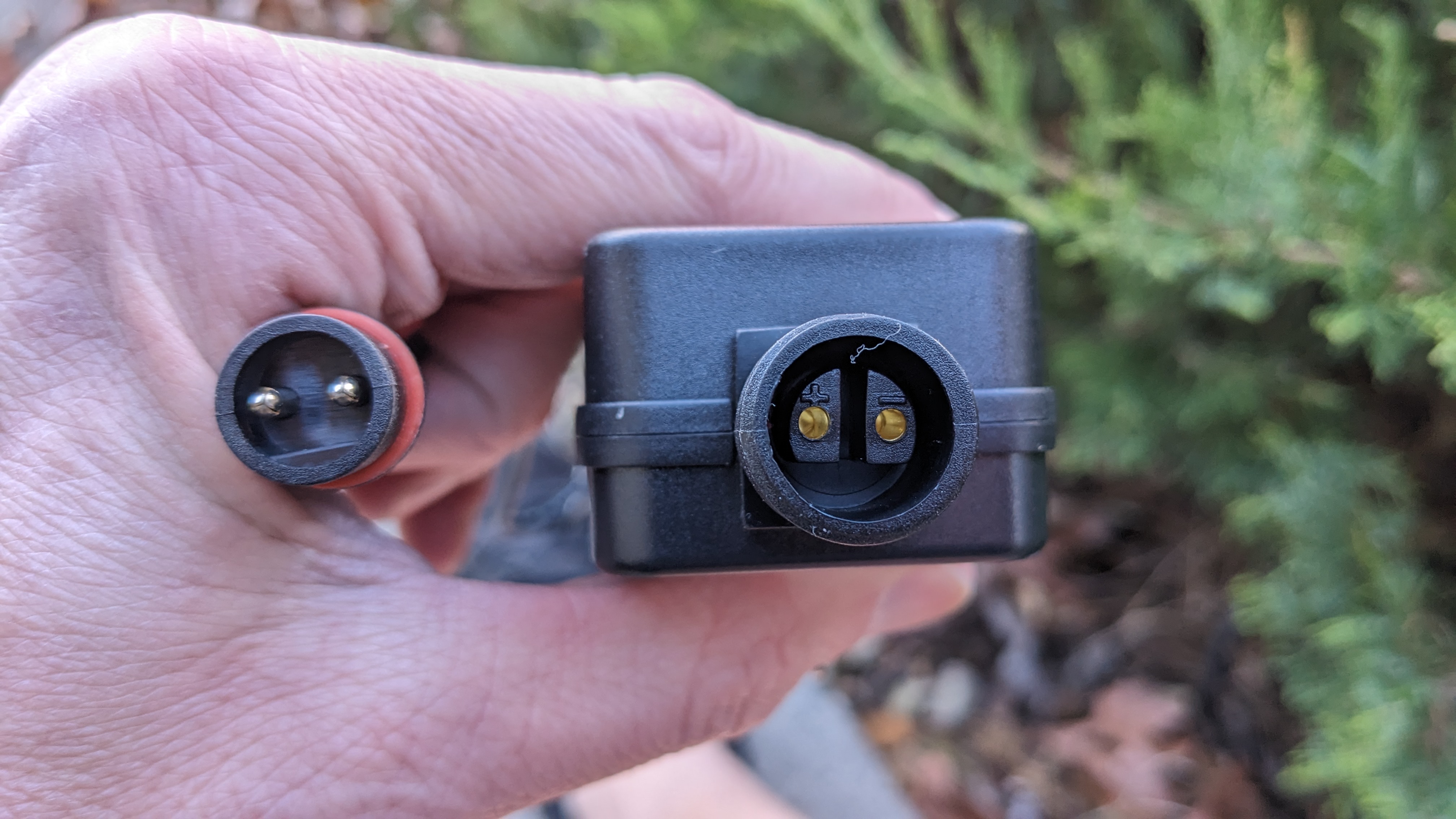
Controller cable connector on the left, power supply connector on the right.
The controller connects to the power supply via a 2 pin round connector.
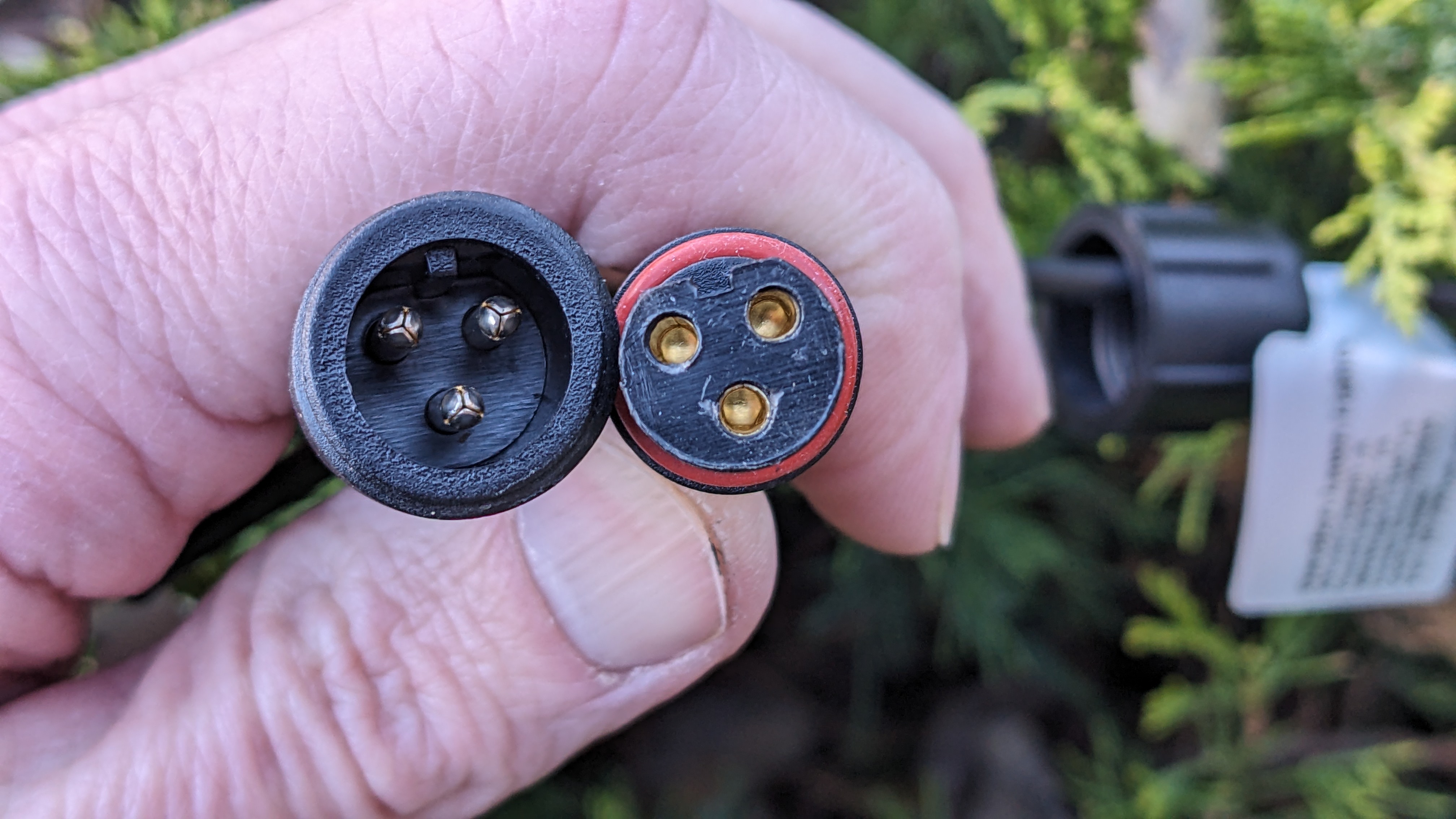
Male light string connector on the left, female controller connector on the right.
The controller connects to the lights via a 3 pin round connector. These connectors are the same size as HolidayCoro / xConnect connectors but the pins and sockets are spaced slightly different so they are not compatible with each other.
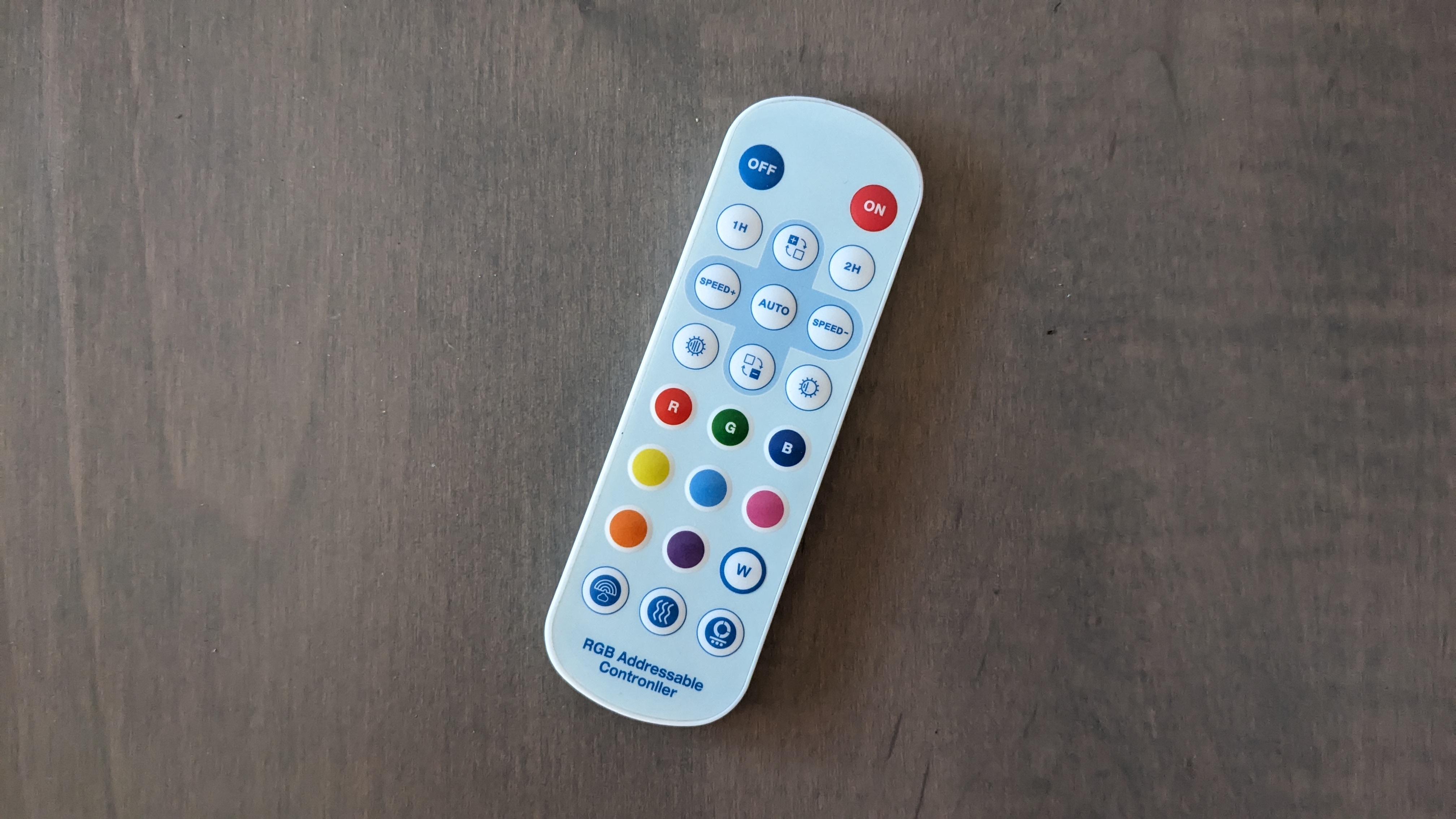
The included RF remote control.
The lights’ basic functionality can be controlled via the included RF remote control or, for more advanced functionality, via the Smart Life – Smart Living app by Volcano Technology Limited. The app does require fine location permission since it uses Bluetooth to discover and pair the lights to your Wi-Fi network.
FCC Info
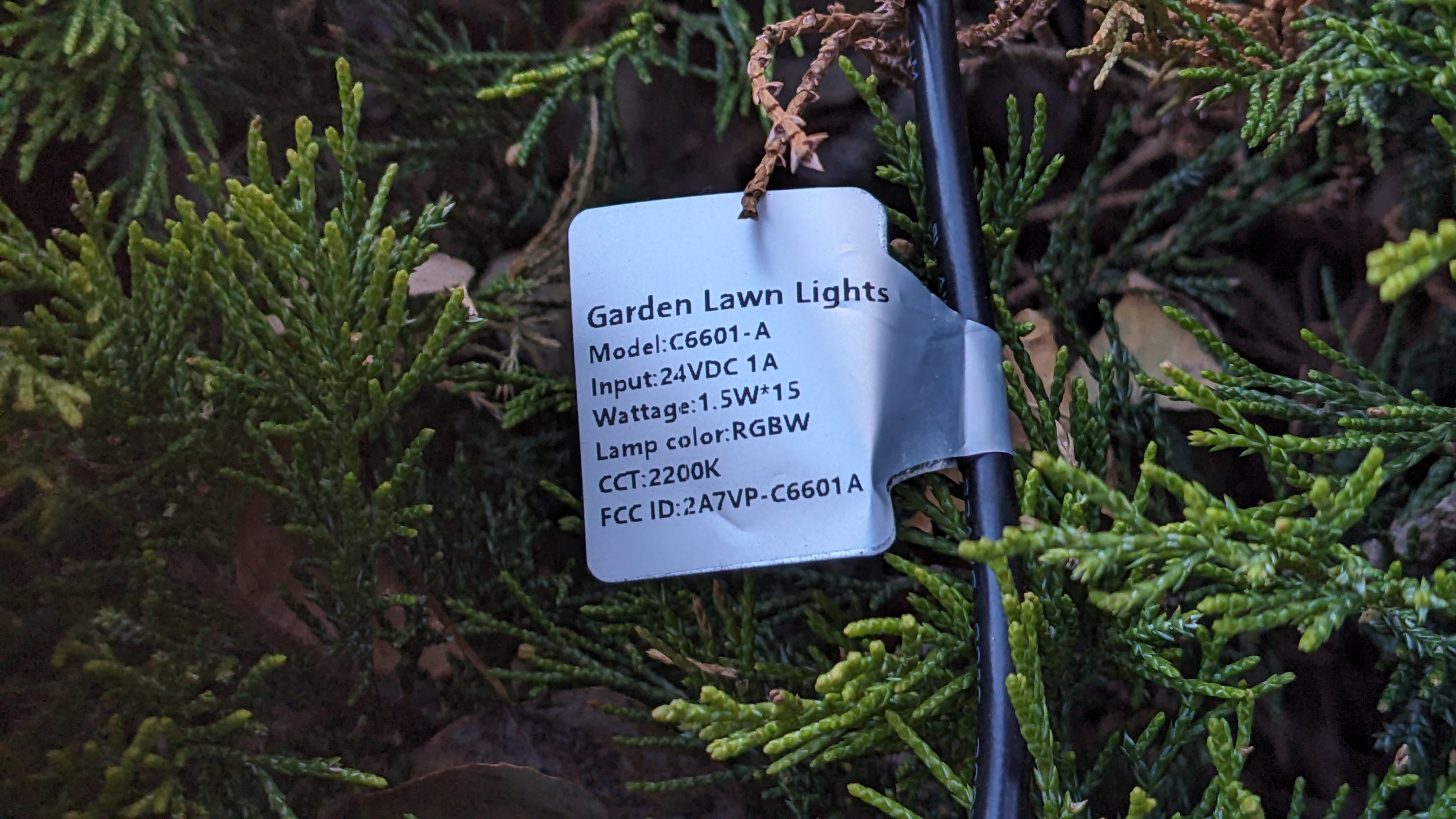
Tag on one of the controller cables with the FCC ID.
The FCC ID of 2A7VP-C6601A on the tag reveals the light is manufactured by the Shenzhen Jindian Zhiguang Lighting Co., Ltd.
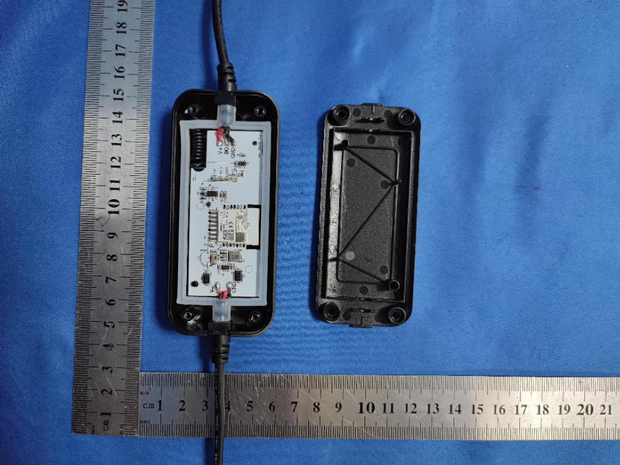
Internal photo of the controller for the lights.
If you head over to fccid.io, you can download PDFs with internal and external photos. The controller is based on a BK7231NQN32 wireless module. From looking at the internal photo, you can see there’s a two wire power input at the bottom of the photos and a three wire power / data output at the top of the photo. The good news here is three wire power / data usually means there’s some sort of WS2811-like control possibility!
Protocol Information
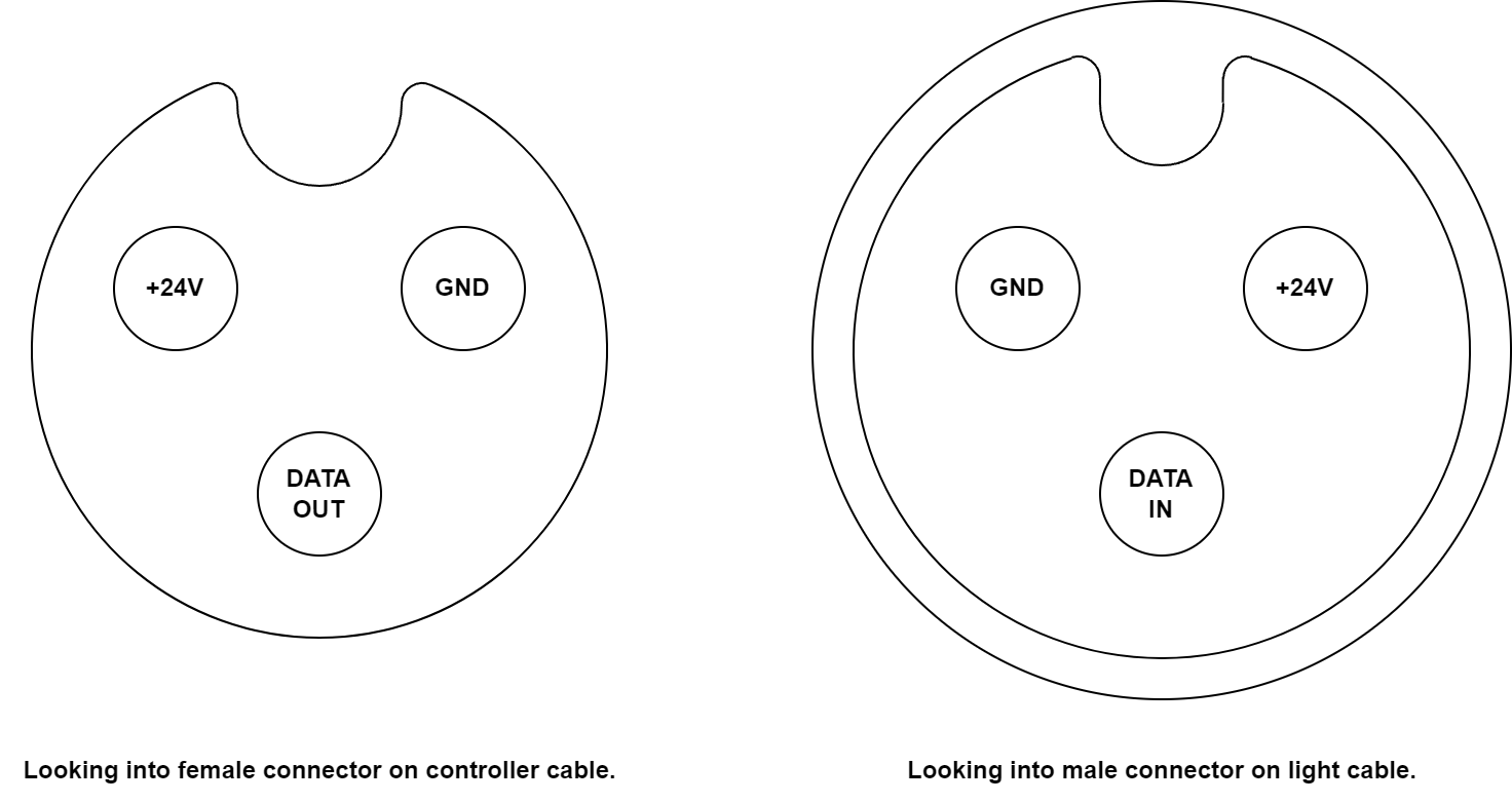
Pinouts drawn looking into the connectors.
The pinout of the connectors is shown above. On the left is the pinout viewed looking into the female connector on the controller cable. On the right is the pinout viewed looking into the male connector on the light cable.
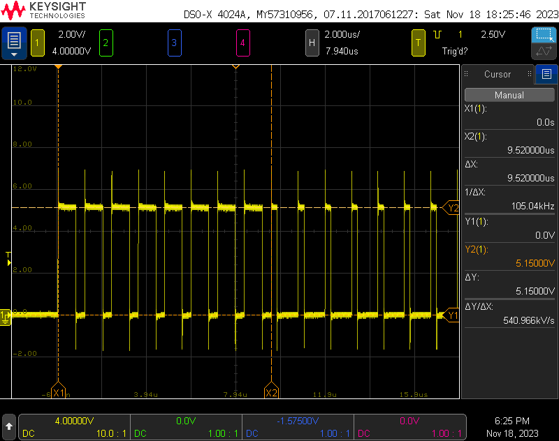
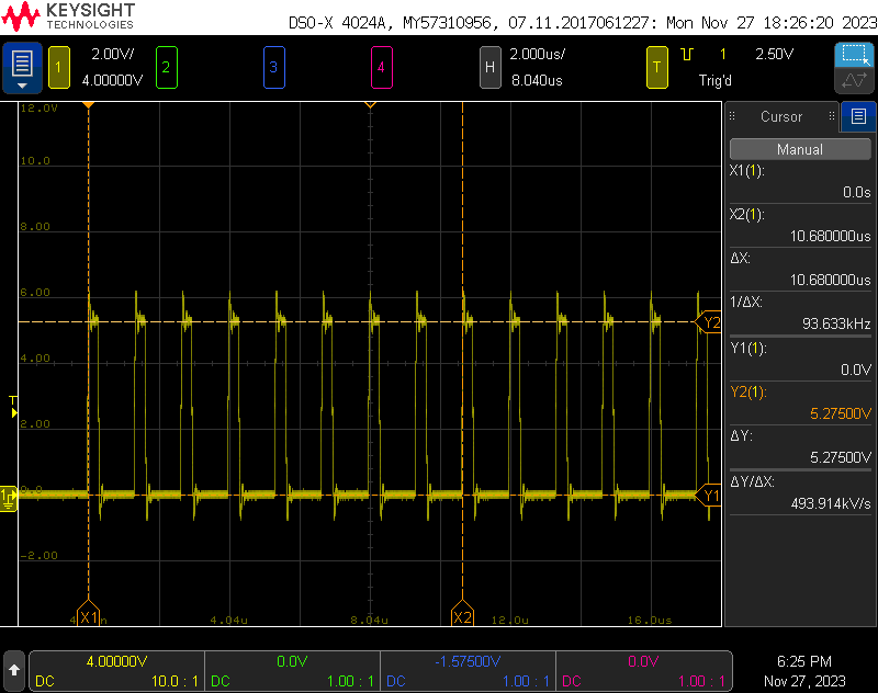
840 kHz bit rate with 5 V logic levels. This is the first light lit up red at 100%.
I hooked the ground and data out pins on the controller cable to an oscilloscope. The waveform was the WS2811 protocol at 840 kHz. Each light had 32 bits of control information. The transmission order was 8 bits of red, 8 bits of green, 8 bits of blue, and 8 bits of warm white. This was repeated 15 times, once for each light on the string.
Controlling with WLED
Hardware Connections
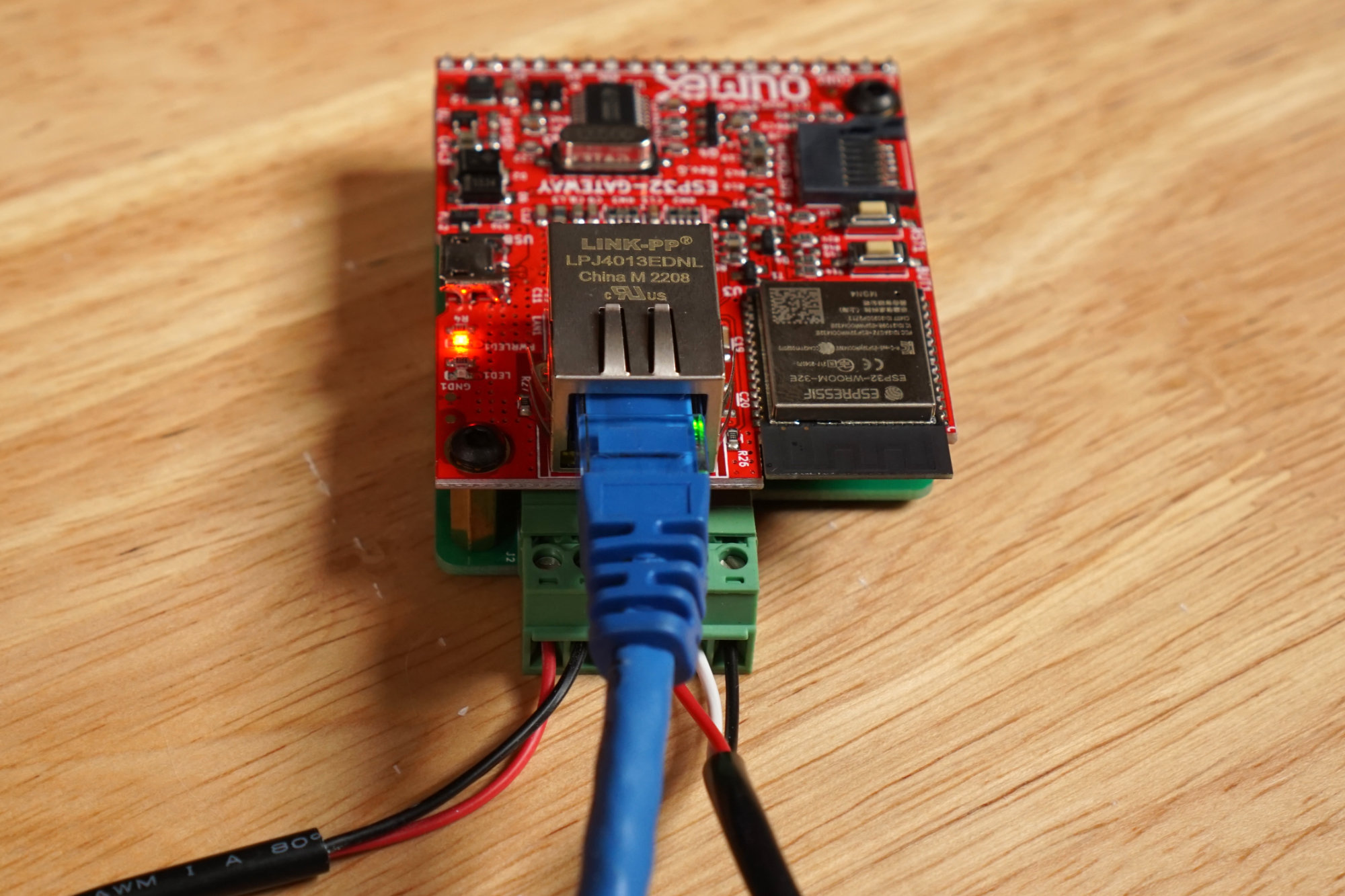
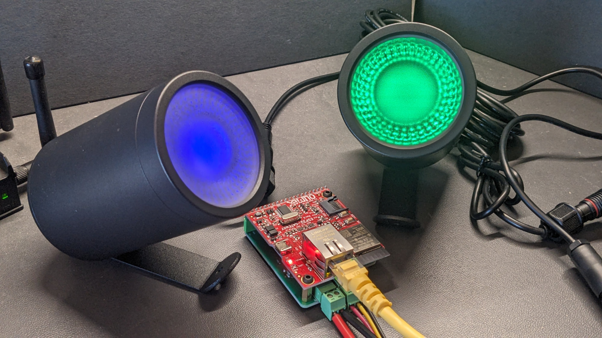
The power supply, light string, and network connected to my WLED controller.
The hardware connections are pretty simple thanks to the interface board. The power supply connects to the 2-pin connector on the left and the lights connect to the 3-pin connector on the right.
WLED Configuration
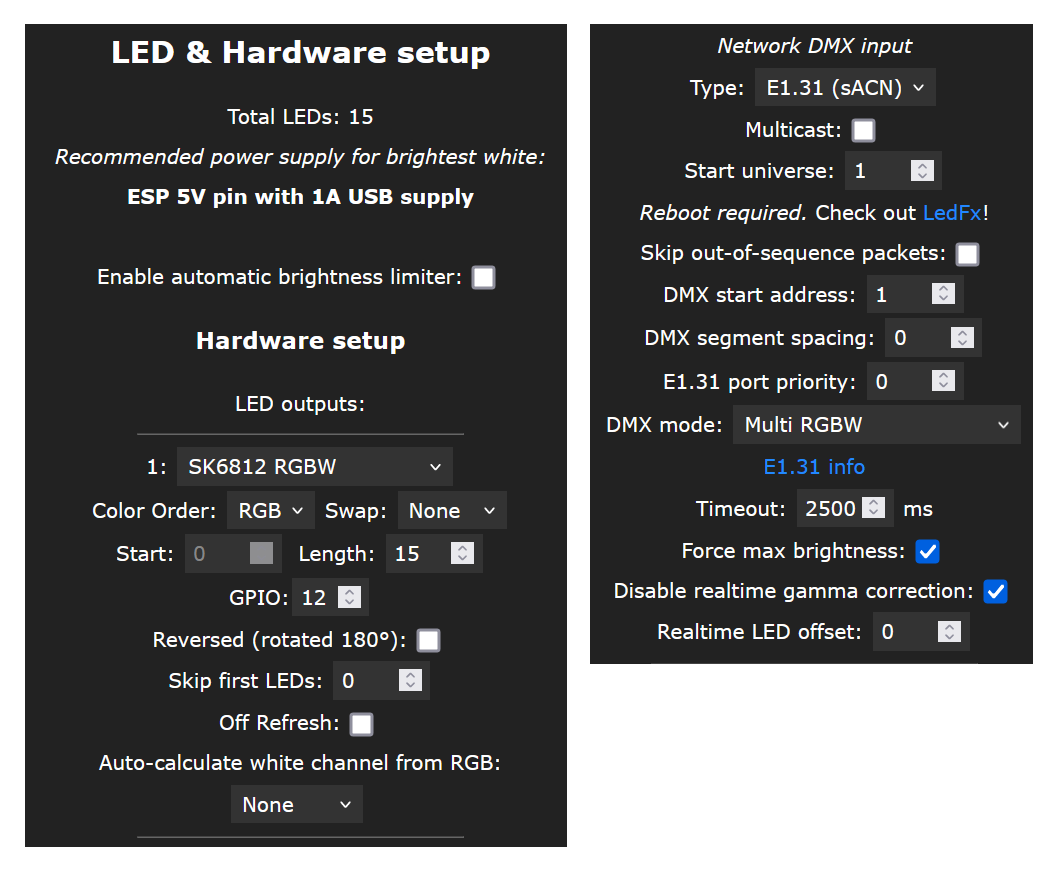
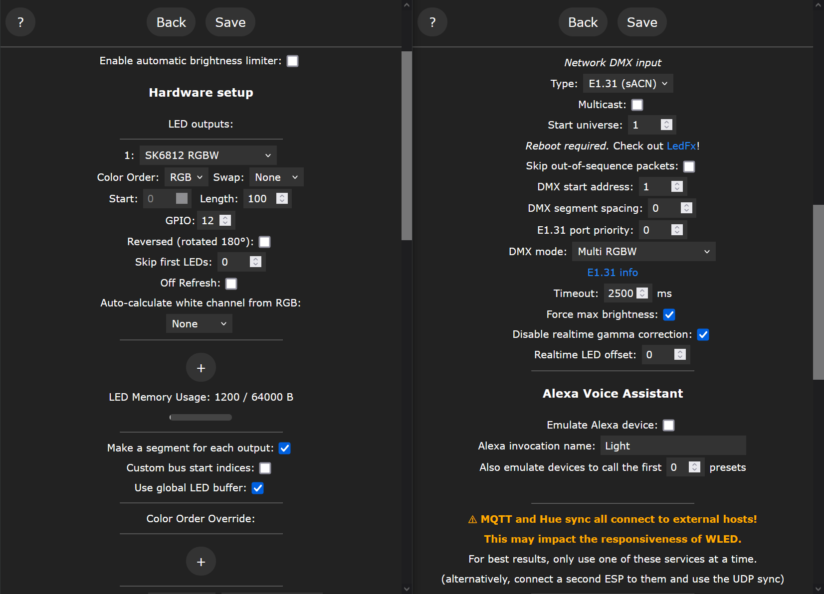
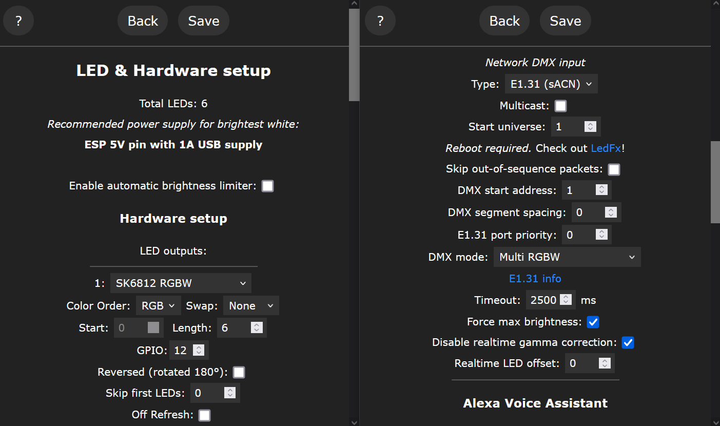
Key parameters in the LED Preferences configuration pane on the left and key parameters in the Sync Interface configuration pane on the right.
To use these lights with WLED, the closest matching pixel type is SK6812 RGBW with RGB color ordering. Selecting this pixel type and color ordering in the LED Preferences panel will permit the pathway lights to use all of WLED’s built-in effects. To control the pathway lights over the network, be sure to select Multi RGBW from the Sync Interfaces panel to match the RGBW pixel type.
Verdict
All WLED features including the large selection of built-in effects are available and the pixels are controllable through both the web interface and over the network using either sACN E1.31 or DDP. I liked these lights and used them in my 2023 holiday light setup.
Set #2: APPECK Low Voltage Landscape Lights, Set of 6
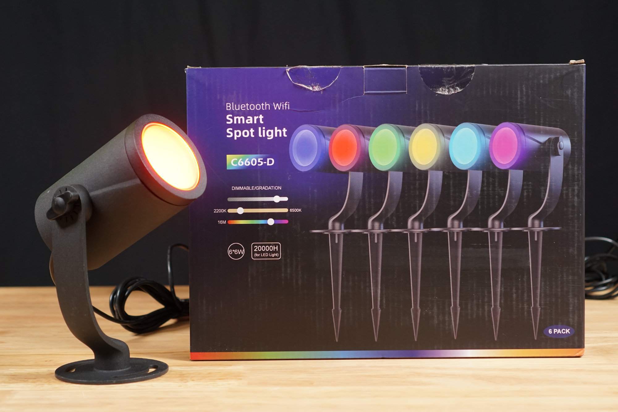
The spotlight box and one of the spotlights.
Next up are the 6 pack of APPECK Smart RGBICW Color Changing Landscape Lights. I purchased one box at $199.99 minus a $99 coupon for a total of $100.99 + tax.
Detailed Description
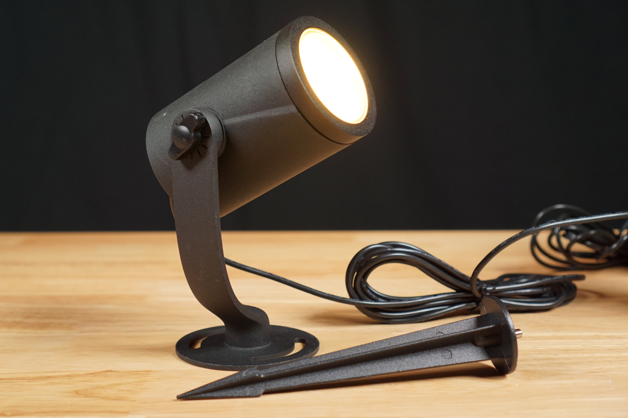
Both the spotlight and stake are constructed of metal and powder coated.
These are small RGB + CCT white landscape lights. CCT means the light includes both warm white and cool white LEDs so the color temperature of the white light can be smoothly adjusted to anywhere from a warm yellowish light to a cool blueish light. They look like spot lights but the beam angle is pretty wide and they function more like flood lights than spot lights. Each light is about 2.5″ in diameter and 4″ long. The attached bracket can be screwed into a wall, ceiling, or deck or the included spike can be attached for fixing the light on the ground. The distance between each light is about 10 feet.
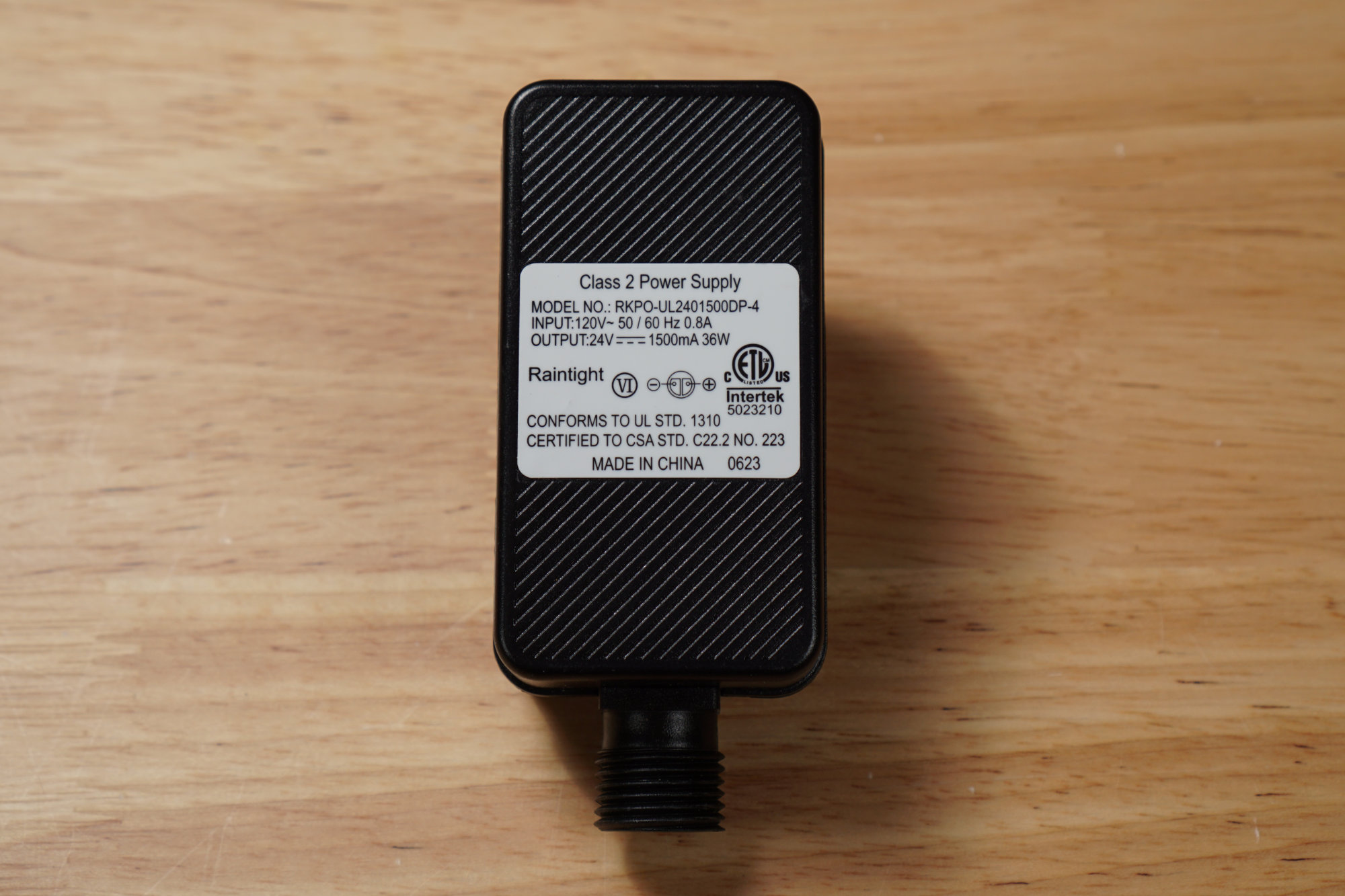
The 24 V 1.5 A / 36 W power supply included with the spotlights.
Each set consists of a power supply, a controller, and six lights. The power supply and controller are very similar to those included with the APPECK pathway lights above. The power supply plugs directly into the wall and is rated for 24 V at 1.5 A or 36 W.
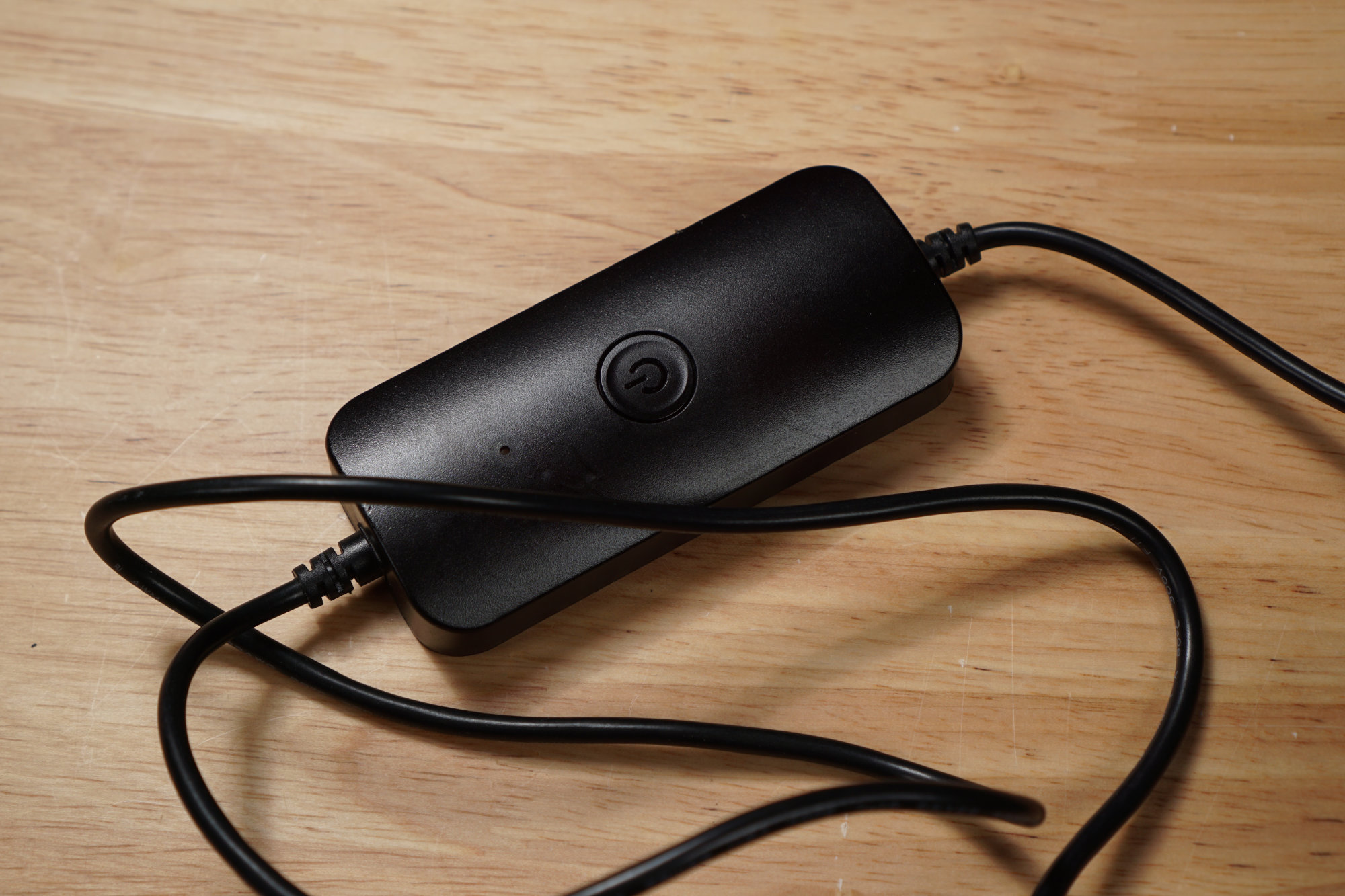
The controller for the spotlights. It looks identical to the controller for the pathway lights. It’s not.
The controller looks identical to the controller included with the APPECK pathway lights above. Again, it’s a black plastic puck with a single button to turn the lights on and off, change light patterns, and enter pairing mode. Even though the controller looks similar, it appears as a different model in the Smart Life app and uses a different protocol than the pathway lights.
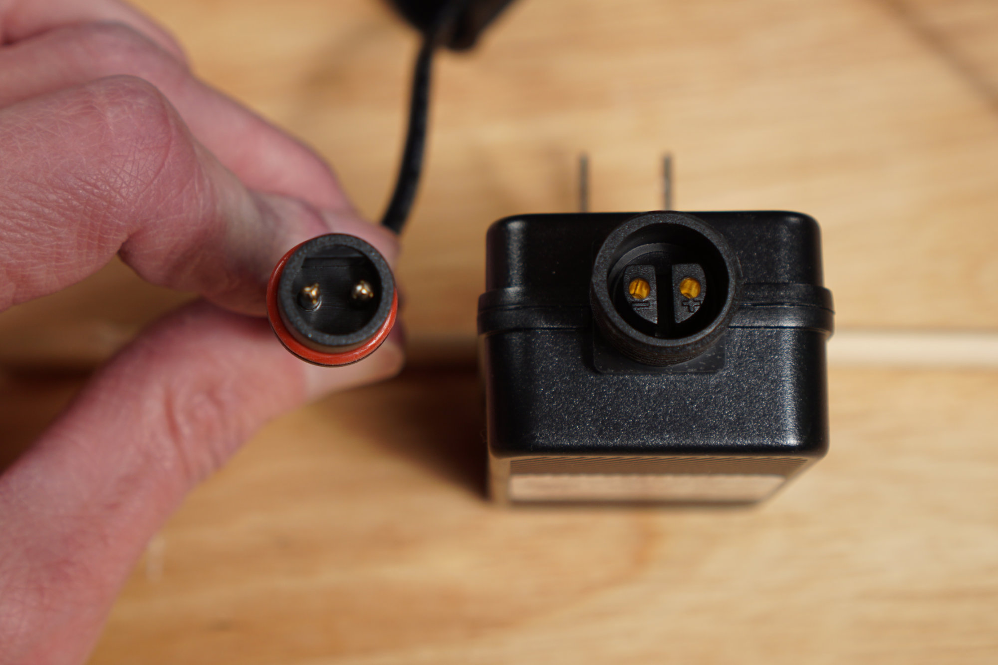
Controller power cable connector on the left, power supply and power supply connector on the right.
The controller connects to the power supply via a 2 pin round connector.
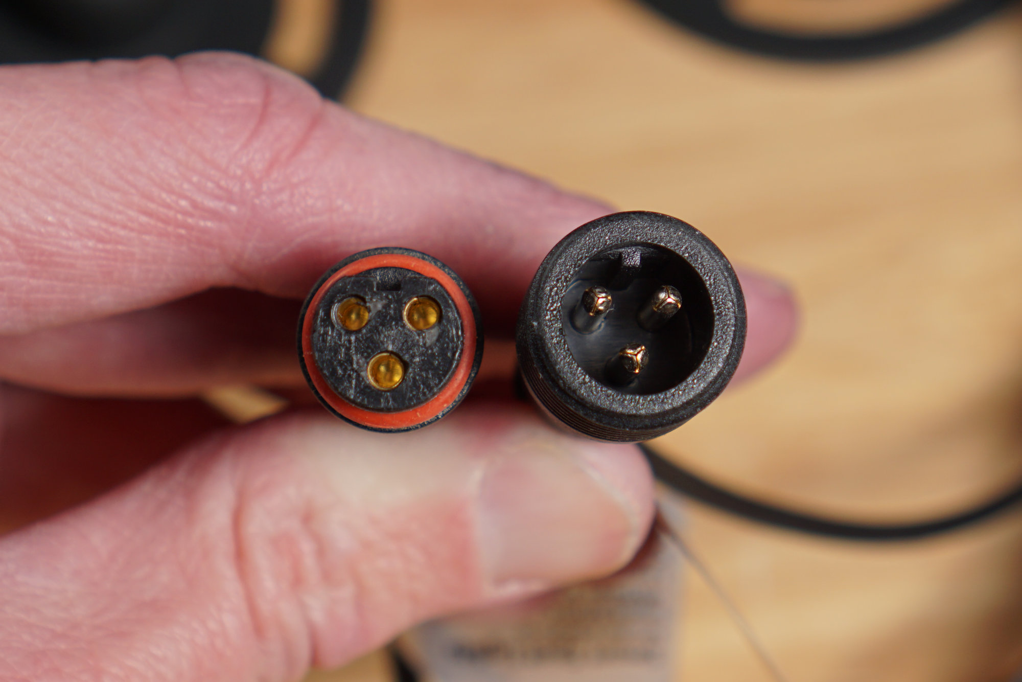
Female controller connector on the left, male light string connector on the right.
The controller connects to the lights via a 3 pin round connector. These connectors are the same size as HolidayCoro / xConnect connectors but the pins and sockets are spaced slightly different so they are not compatible with each other.
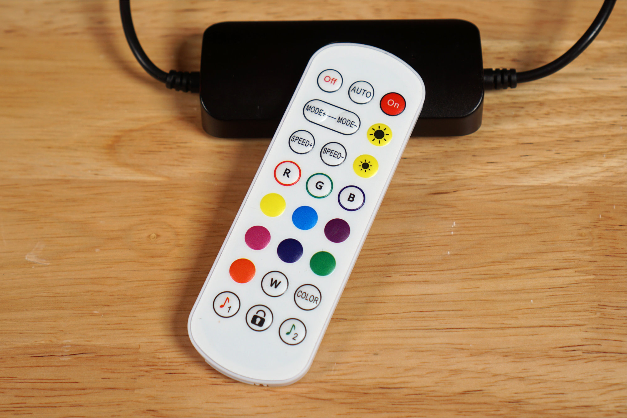
The RF remote control for the spotlights.
The lights’ basic functionality can be controlled via the included RF remote control or, for more advanced functionality, via the Smart Life – Smart Living app by Volcano Technology Limited. The remote is slightly different than the one included with the pathway lights. The remotes from the flood lights and the pathway lights do not interfere with each other. The app does require fine location permission since it uses Bluetooth to discover and pair the lights to your Wi-Fi network.
FCC Info
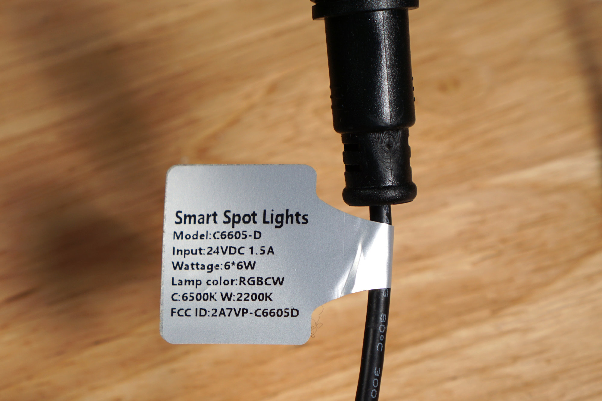
Label on the string of spotlights with the FCC ID.
The FCC ID on the tag is 2A7VP-C6605D.
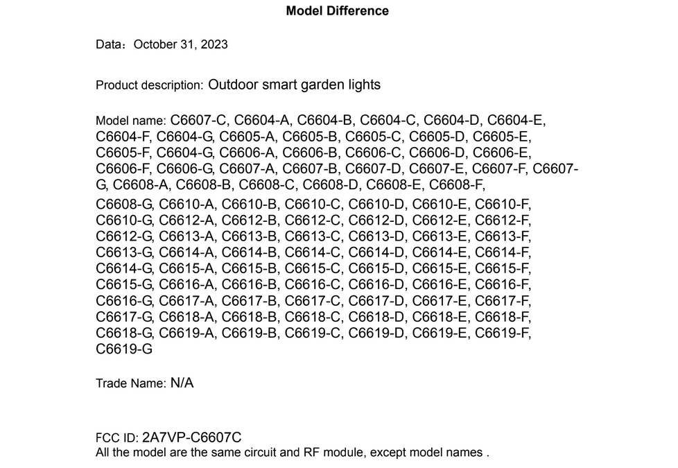
Searching for the FCC ID reveals a model difference letter. The interesting FCC ID for these lights is 2A7VP-C6607C.
Searching for the 2A7VP-C6605D FCC ID in the FCC database yields a Model Difference letter asserting that the C6605D model is identical in all but form factor and model number to the C6607C model. Searching for the 2A7VP-C6607C FCC ID reveals the meaty FCC entry for the lights. These lights are manufactured by the Shenzhen Jindian Zhiguang Lighting Co., Ltd. Unfortunately, the Internal Photos PDF is being held back until April 30, 2024, under a temporary confidentiality request.
Protocol
Pinouts drawn looking into the connectors.
The pinout of the connectors is shown above. On the left is the pinout viewed looking into the female connector on the controller cable. On the right is the pinout viewed looking into the male connector on the light cable. This is the same pinout as for the APPECK pathway lights described above.
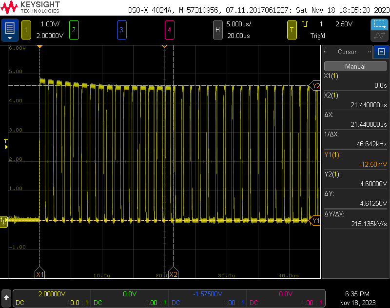
750 kHz bit rate with 5 V logic levels. 16 bits per color. This is the first light lit up red at 100%.
I hooked the ground and data out pins on the controller cable to an oscilloscope. The waveform was the WS2811 protocol at 750 kHz. Each light had 80 bits of control information. The transmission order was 16 bits of red, 16 bits of green, 16 bits of blue, 16 bits of cool white, and 16 bits of warm white. This was repeated 12 times despite there only being 6 lights in the set.
If all these bits are real, the lights can be set to billions of different colors and the high resolution will be useful for gamma correction at low brightness levels. Also, I can’t wait for the FCC to publish the internal photos because I’m really curious what driver chip supports 5 channel of 16 bits each.
Controlling with WLED
Hardware Connections
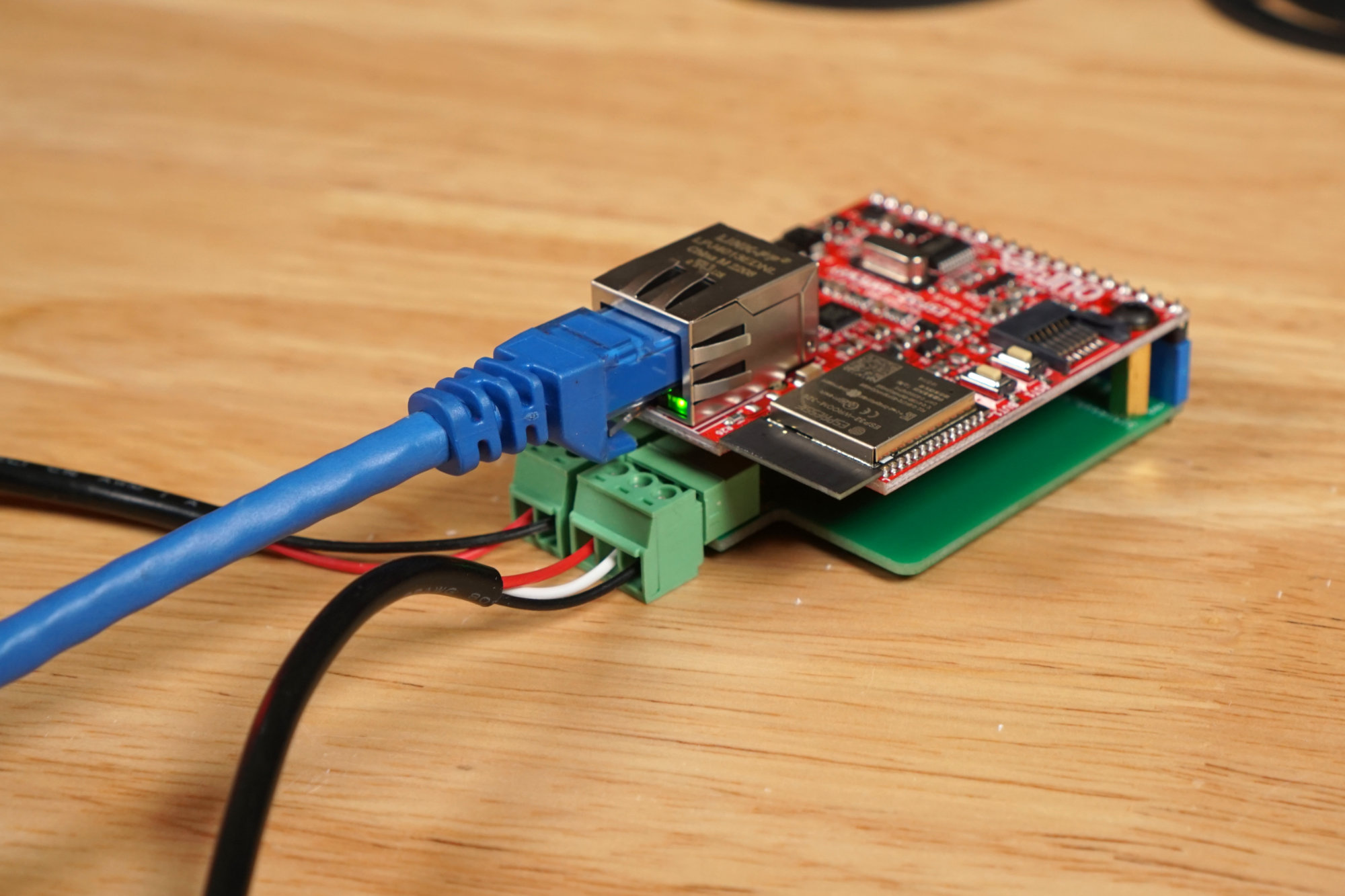
The power supply, light string, and network connected to my WLED controller.
The hardware connections are pretty simple thanks to my interface board. The power supply connects to the 2-pin connector on the left and the lights connect to the 3-pin connector on the right.
WLED Configuration
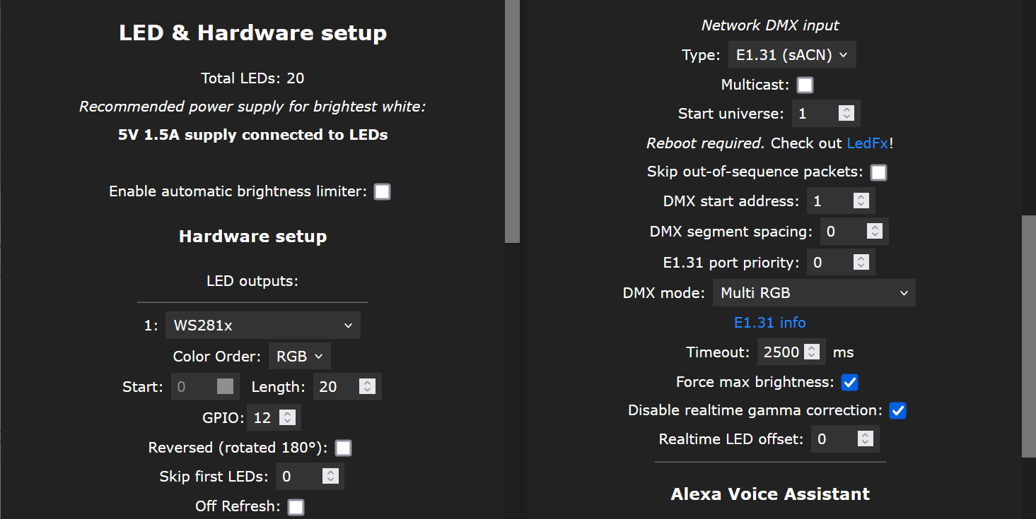
WLED LED and sync interface configuration panels for these lights.
WLED does not support pixels with five 16-bit channels. The best we can do is to configure WLED to transparently pass 60 DMX channels received via sACN E1.31 or DDP to the spotlights then use other software to control the spotlights over the network.
To do this, I configured 20 pixels of WS281x with RGB color ordering in the LED configuration panel, and in the interfaces panels, I selected Multi RGB for the DMX mode and made sure both the Force max brightness and Disable realtime gamma correction boxes were checked.
Verdict
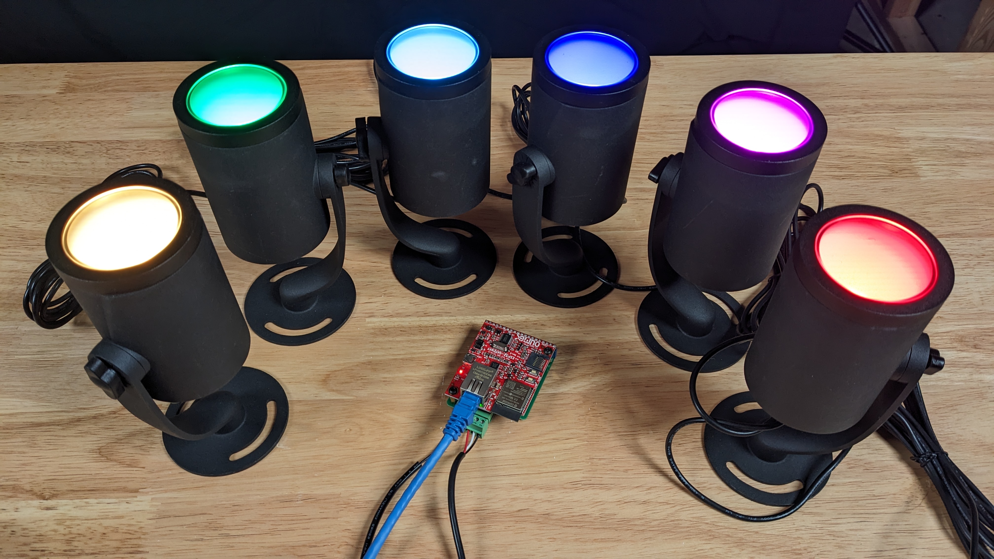
The six spotlights connected to my WLED controller. The light data is being sent over the network from some software that supports 5 channel, 16-bit per channel fixtures.
WLED does not support pixels with five 16-bit channels. As a result, the spotlights are not really controllable through the WLED web interface and few, if any, of WLED’s built-in effects will work with the spotlights. The likely only useful built-in effect is creating an all-black preset to turn off the spotlights in the absence of DMX data.
The spotlights can be controlled, however, via sACN e1.31 and DDP by defining the 6 spotlights as 20 8-bit RGB pixels in WLED and using the Multi RGB DMX mode. In this case, the software sending the e1.31 or DDP packets to the WLED controller must support five channel fixtures with 16 bits per channel.
I will likely use these lights to illuminate larger props at Halloween.
Set #3: Lumary Smart Landscape Lights, Set of 6
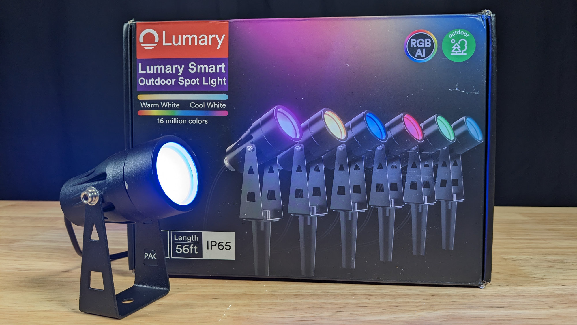
The spotlight box and one of the miniature spotlights.
Next up is a 6 pack of Lumary Smart Outdoor Spotlights. I purchased one box for $69.99 + tax.
Detailed Description
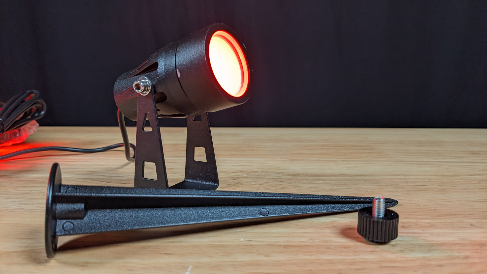
Both the spotlight and stake are constructed of metal and powder coated.
These are the smallest of the lights I examined. They’re only 1.5″ in diameter and about 3″ long. They’re also the lowest powered and least bright of the lights I examined. The entire set is powered by a 12 V at 1 A or 12 W adapter. The other light sets have power adapters with at least twice the wattage.
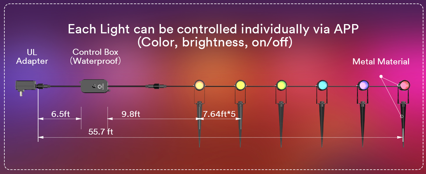
System components and the distances between them.
Like the previous two sets, this set consists of a plugin AC power supply, a controller, and a string of lights. The seller’s photo above shows a schematic of the set and the distances between each component of the system.
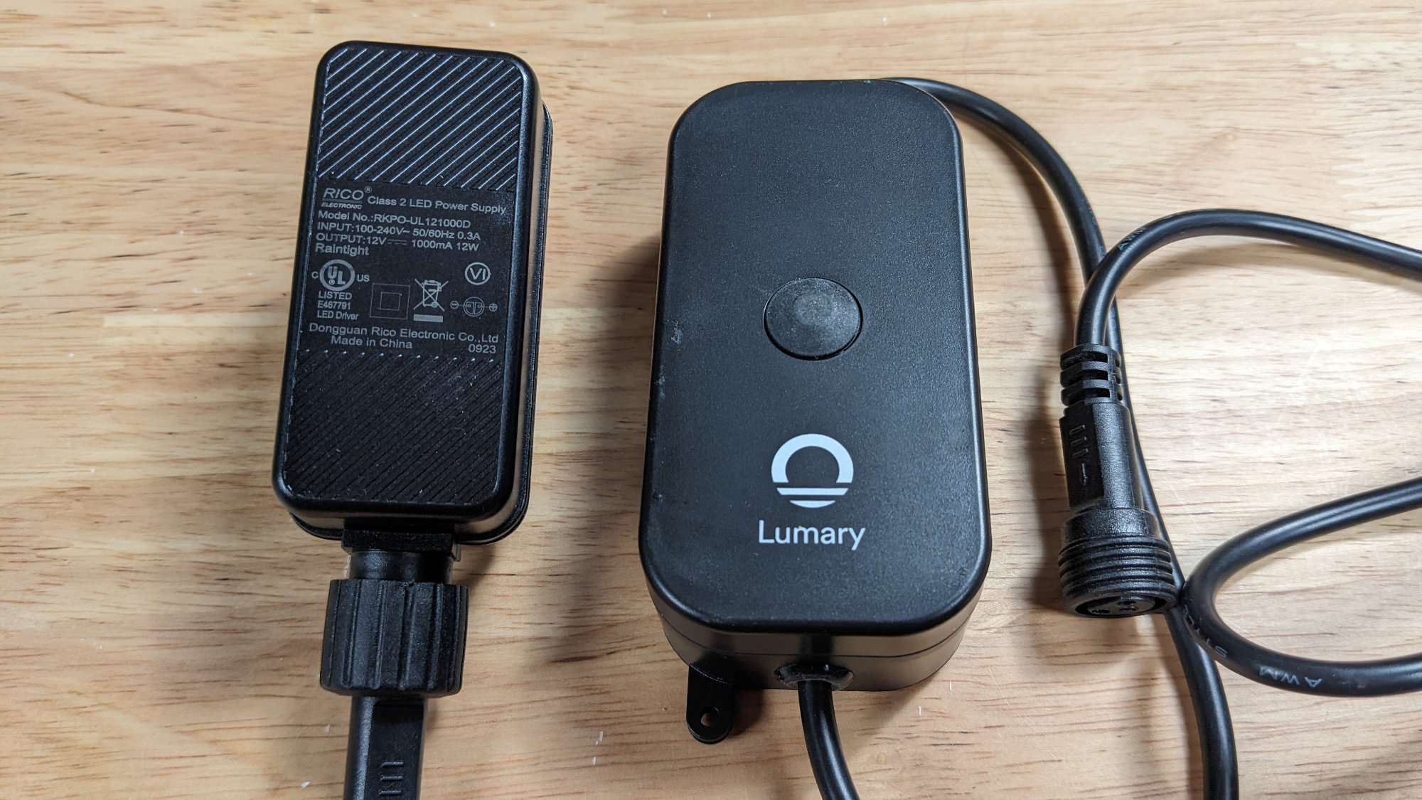
The 12 V 1 A / 12 W AC adapter and controller.
The power adapter and controller are shown in the photo above. The power and light cables are permanently attached to the controller. The controller’s power cable connects directly to the power supply. The controller’s light cable connects to a long lead wire from the first fixture in the string. Note that unlike the previous two sets, the power supply is only 12 V at 1 A / 12 W.
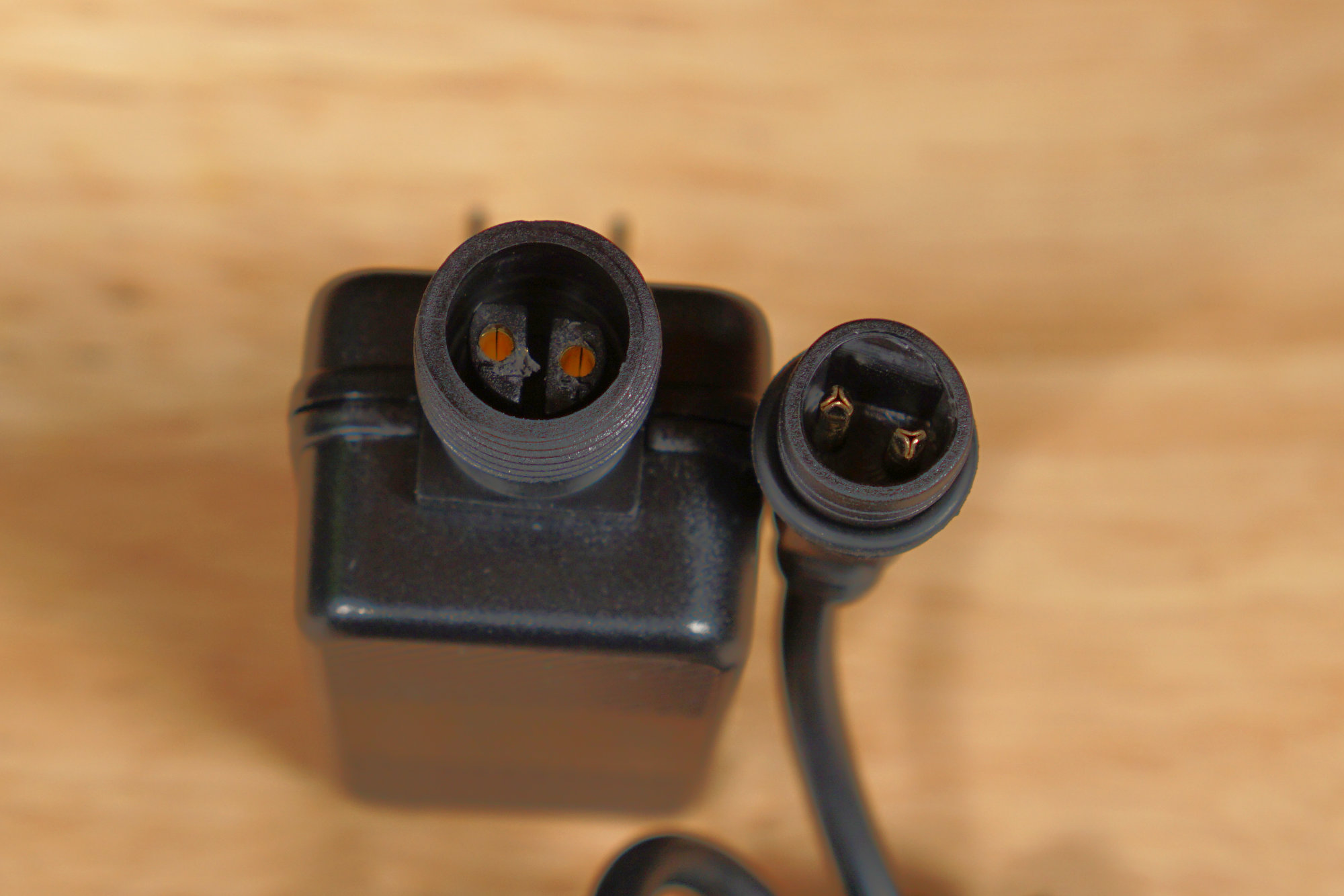
Power supply and power supply connector on the left, controller power cable connector on the right.
The controller connects to the power supply via a 2 pin round connector.
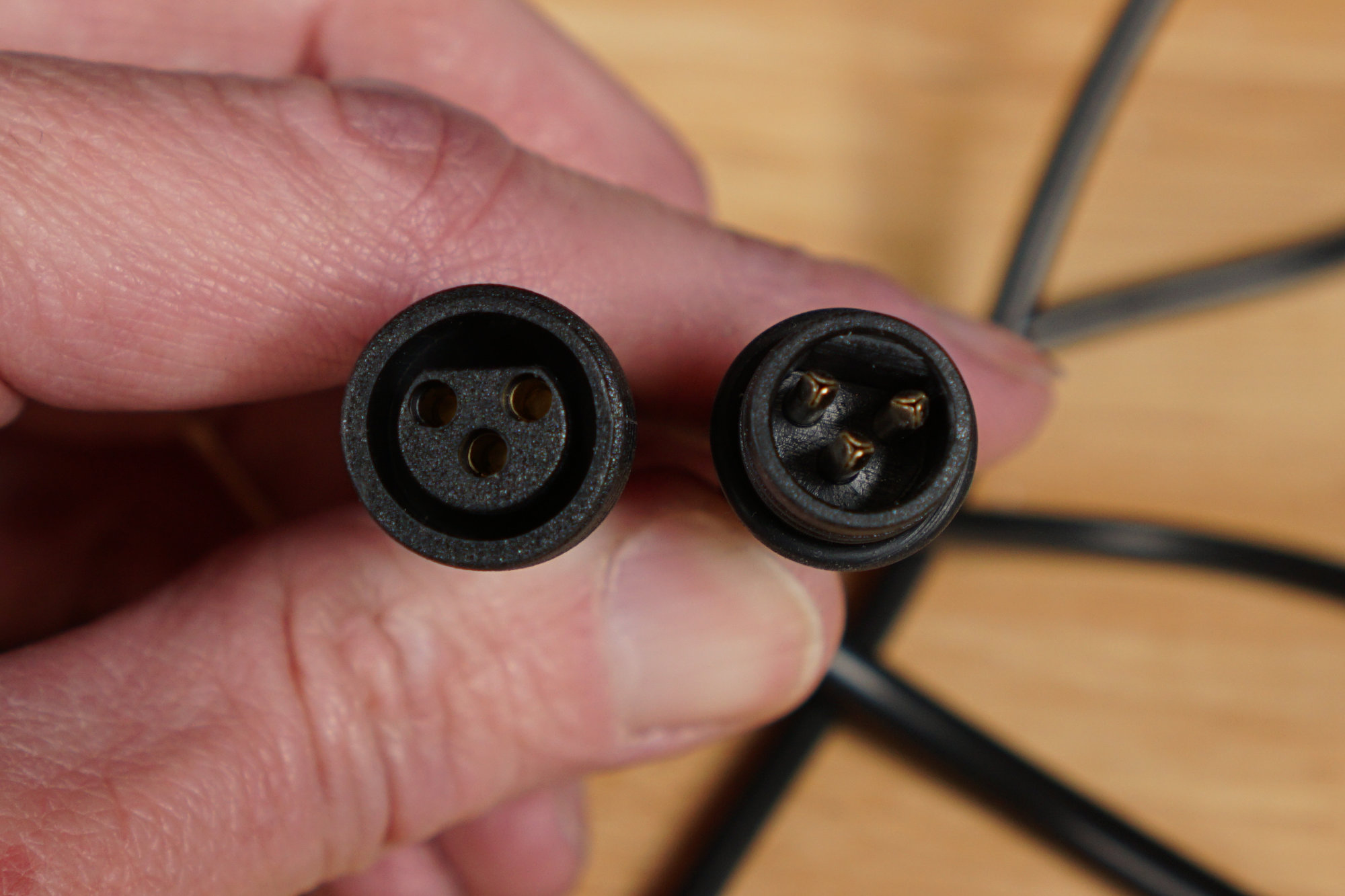
Female controller connector on the left, male light string connector on the right.
The controller connects to the lights via a 3 pin round connector. These connectors are slightly different than the connectors used on the previous two sets.
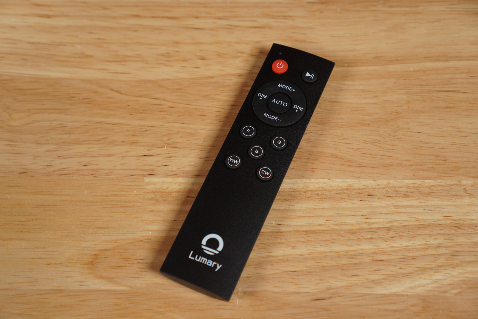
The remote control included with the set. I never could get it to work. It looks like it’s an IR remote rather than an RF remote.
This set included the fanciest remote of the lot. It appears to be an IR remote control powered by 2 AAA batteries. I could never get it to work.
Ignore the Bundled App
The QR code in the instruction manual links to the Lumary app. Unfortunately, the Lumary app requires an account with a verified email address to use the app and lights. Instead of using the bundled app, use the Tuya Smart Life app instead. The Tuya app has no problem pairing with these lights and controlling them. It also has the advantage that it’s the same app for all the lights I’ve examined in this post.
FCC Info
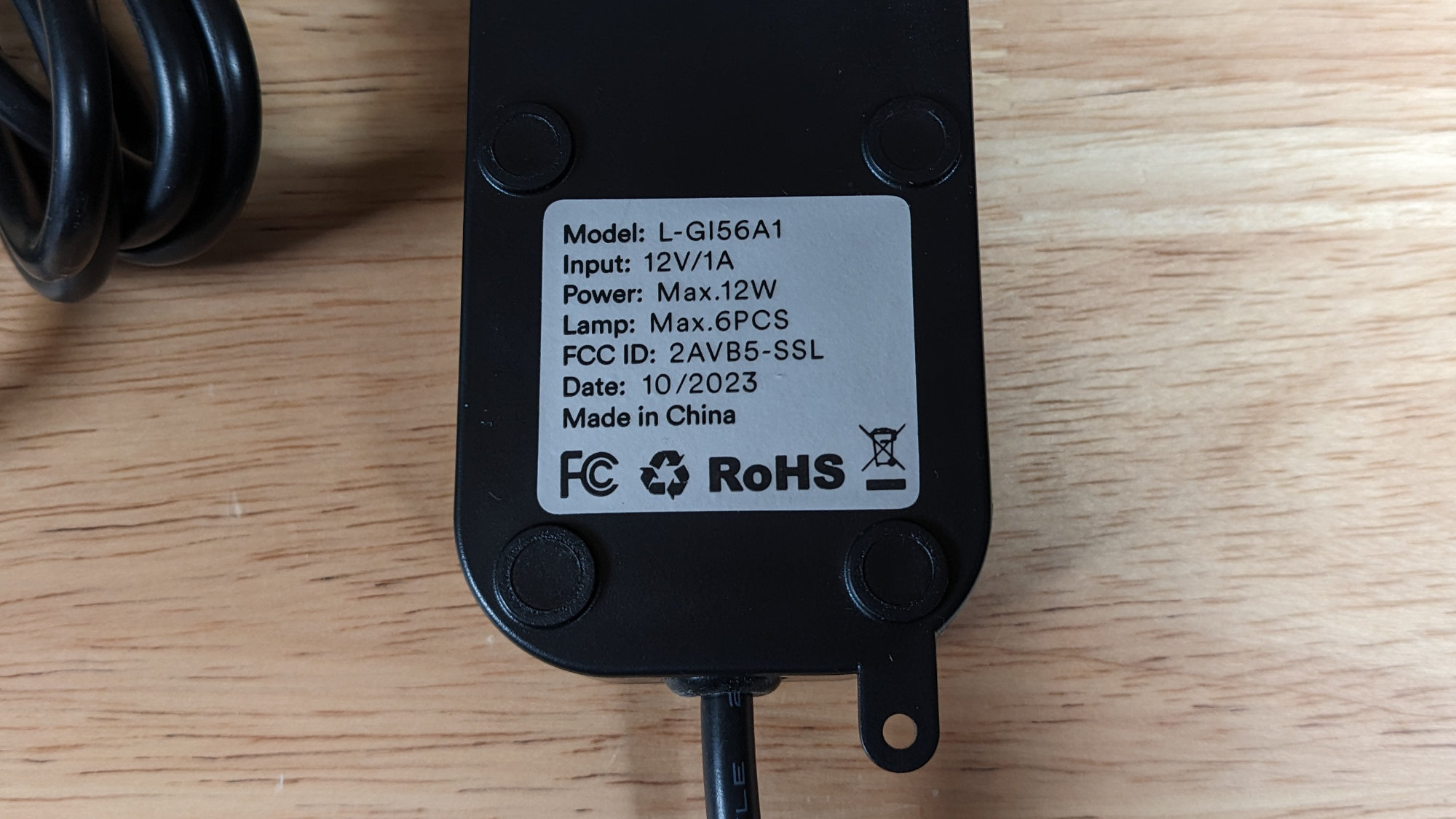
The FCC ID according to the label on the back of the controller is 2AVB5-SSL.
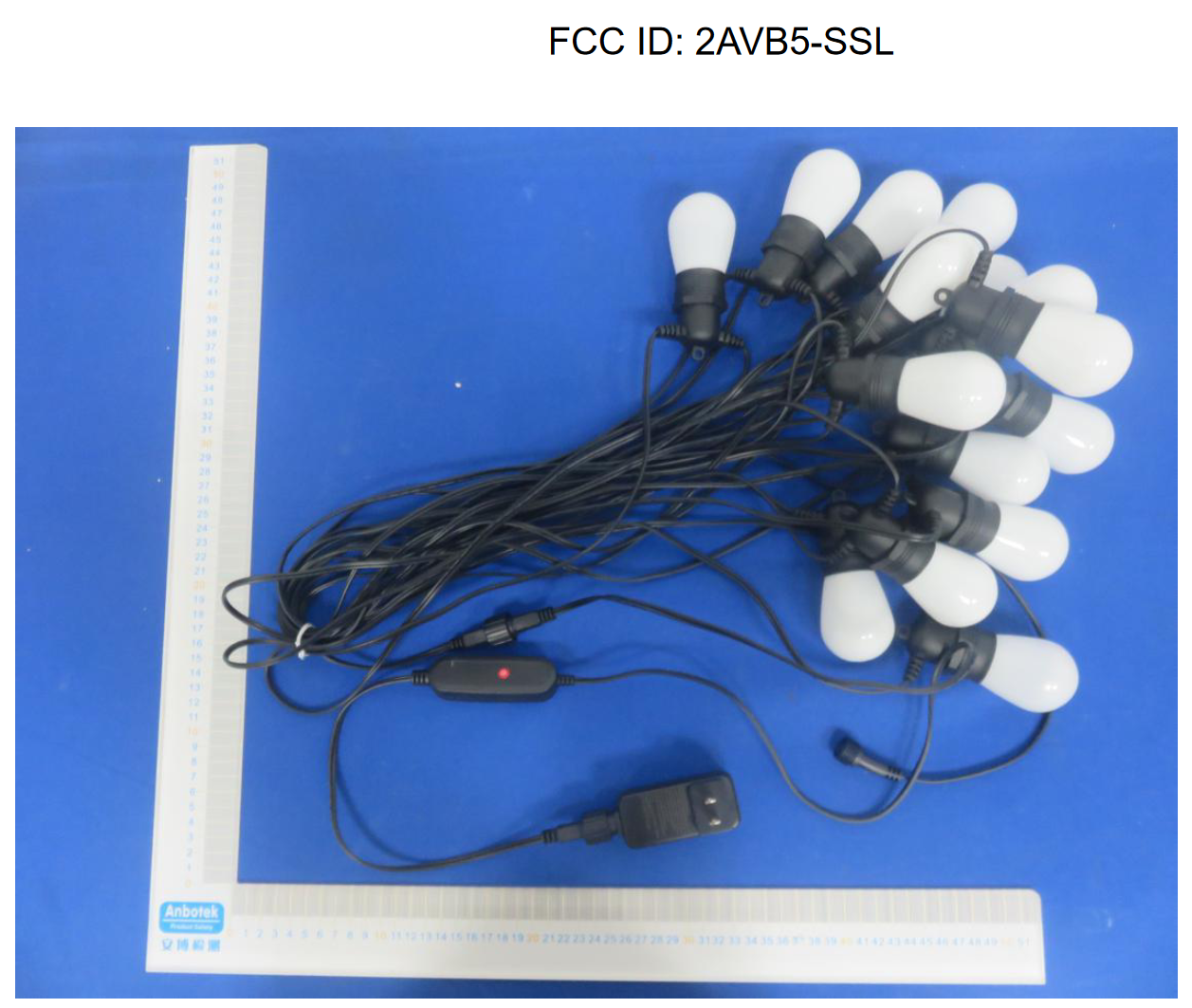
The real product associated with this FCC ID?
Searching fccid.io for the FCC ID on the controller links to a database entry for a patio light string made by the Shenzhen Andysom Lighting Co., Ltd. The power adapter and controller have different form factors as well. I guess it’s possible the guts are the same between products and that the FCC database is just missing a Model Difference letter. Still seems a bit sus.
Protocol
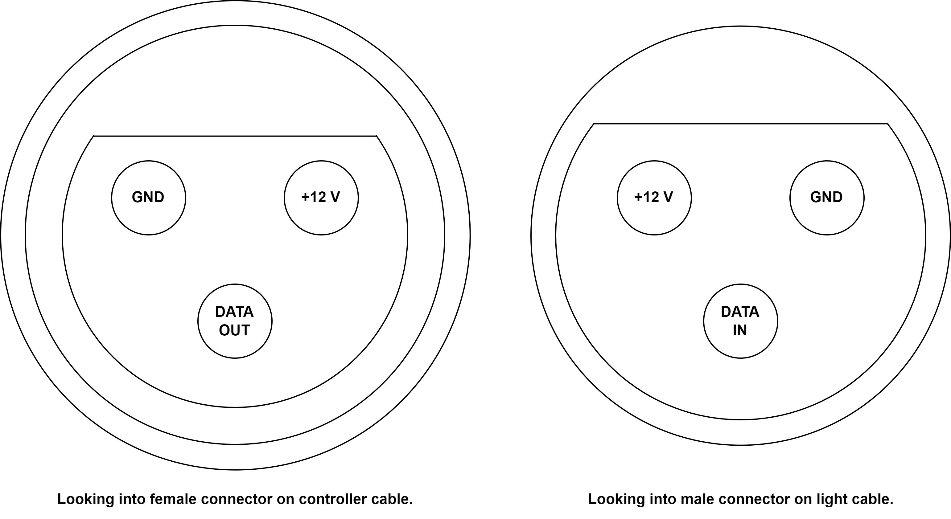
Controller and light cable connector pinouts.
The pinout of the connectors is shown above. On the left is the pinout viewed looking into the female connector on the controller cable. On the right is the pinout viewed looking into the male connector on the light cable.
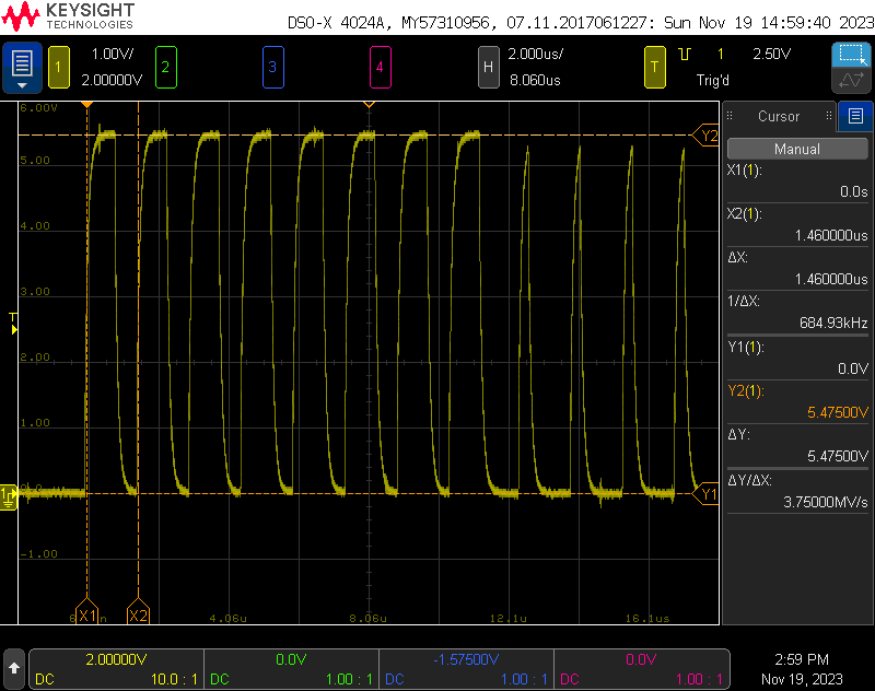
Scope trace with the first light set to 100% red. 685 kHz, 5 V logic levels and 8 bits per channel.
I hooked the ground and data out pins on the controller cable to an oscilloscope. The waveform was the WS2811 protocol at 685 kHz. Each light had 32 bits of control information. The transmission order was 8 bits of red, 8 bits of green, 8 bits of blue, and 8 bits of warm white. Even though there are only six lights on the string, the controller sent data for 100 lights.
Controlling with WLED
Hardware Connections
Oh no! White, green, and black wires instead of the usual red, white, and black wires.
I cut the light cable off the controller and pulled back the outer jacket to reveal white, green, and black wires instead of the usual red, white, and black wires. I used a DMM and scope to find the power, data, and ground wires. For this set of lights, the white wire was +12 V, the green wire was data, and the black wire was ground.
WLED Configuration
WLED LED and sync interface configuration panels for these lights.
To use these lights with WLED, the closest matching pixel type is SK6812 RGBW with RGB color ordering. Selecting this pixel type and color ordering in the LED Preferences panel will permit the lights to use all of WLED’s built-in effects.
If the exact number of lights in the string (6) is entered for the number of pixels, the lights will flicker horribly, especially on the white channel. The stock controller sends 100 lights of data. I recommend configuring WLED for 100 pixels even though there’s only six lights on the string.
To control these lights over the network, be sure to select Multi RGBW from the Sync Interfaces panel to match the RGBW pixel type.
Verdict
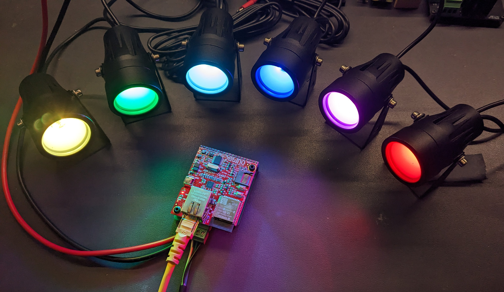
The six miniature spotlights placed around the WLED controller.
With these lights, all WLED features including the large selection of built-in effects are available and the pixels are controllable through both the web interface and over the network. Just be sure to set the number of pixels to 100 in the WLED LED configuration panel to prevent flickering. I will likely use these lights to illuminate smaller props like zombie ground breakers at Halloween.
Set #4: ALFELE RGBCW Outdoor Flood Lights, Set of 6
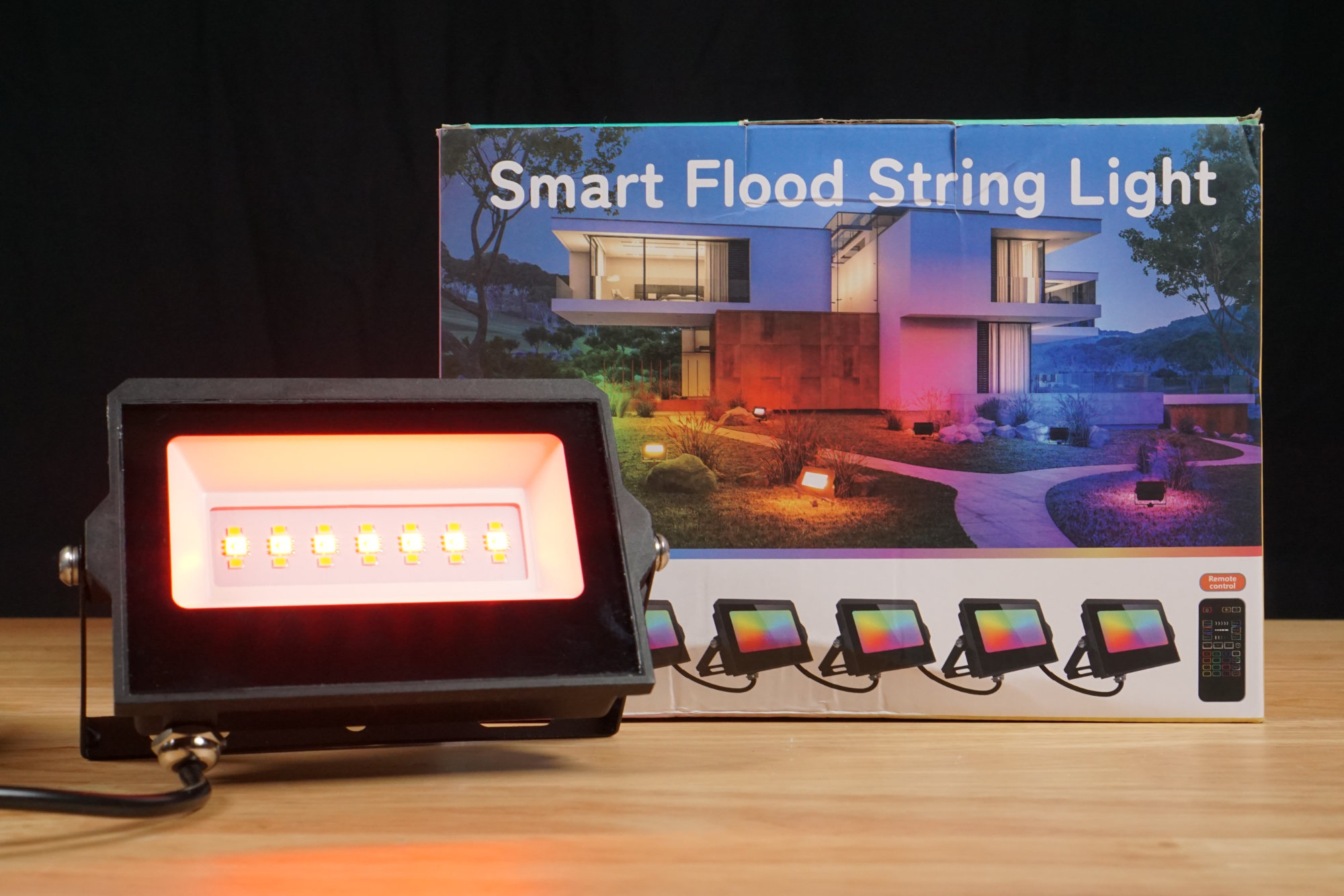
No branding on the box for these lights.
Finally, the last set to examine is the set of 6 ALFELE RGBCW Outdoor Flood Lights. I purchased one set for $99 minus a $15 lightning deal and a $30 coupon for a final price of $54 plus tax.
Detailed Description
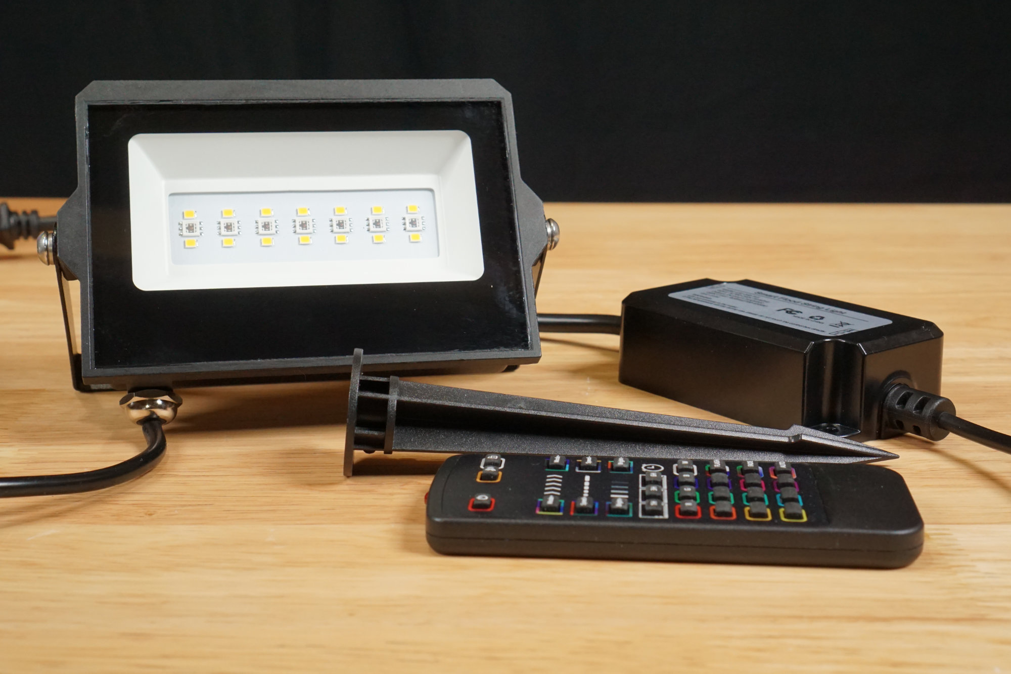
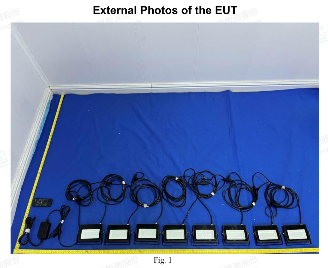
The set includes six lights, six plastic stakes, the nuts and bolts to connect the spikes to the lights, a power data supply, and an RF remote control.
These lights are the first floodlights that actually look like floodlights! These lights consist of heavy aluminum enclosures with transparent glass fronts. Each light measures about 5.25″ x 3.75″ x 1.25″ and there is 3 meters of cable between each light. Behind the glass are 2 rows of seven warm white LEDs with a row of seven combination RGB LEDs between them.
The lights can be mounted to a wall, ceiling, or deck using the included mounting brackets or anchored to the ground using the included plastic spikes that attach to the mounting brackets. Unlike the other lights, these lights incorporate the AC power supply and wireless control electronics into a single monolithic brick that I’m calling a power data supply.
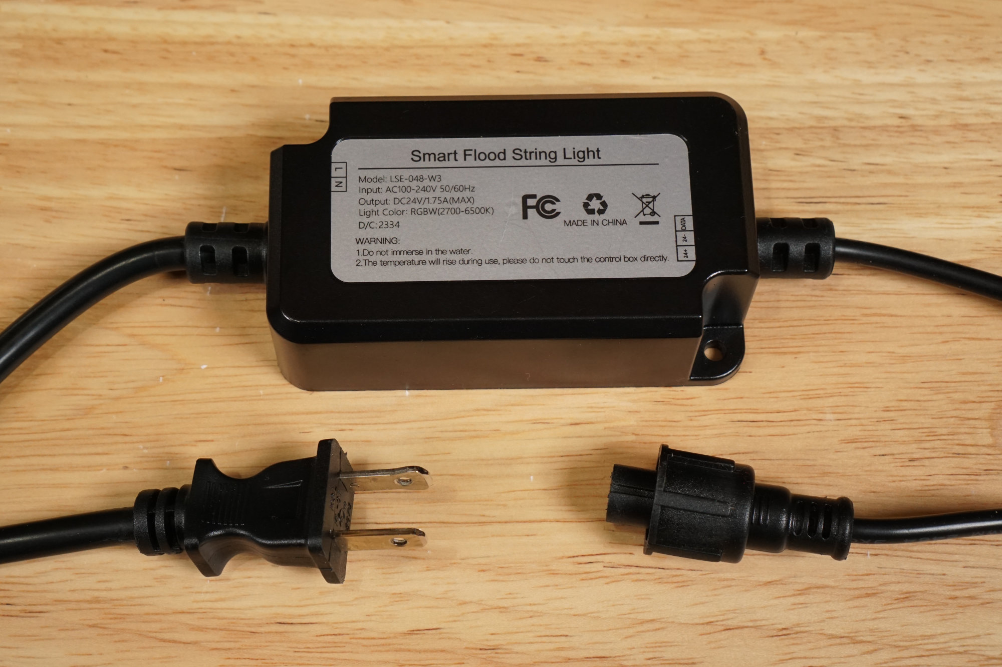
The power supply for these lights also houses the Wi-Fi/BLE/RF controller.
The power data supply is shown in the photo above. The AC line cord is on the left and the power/data cable to the lights is on the right. The power/data cable connects to the first light in the string using a waterproof 3-pin connector. The power supply is rated for 24 V at 1.75 A or 42 W.
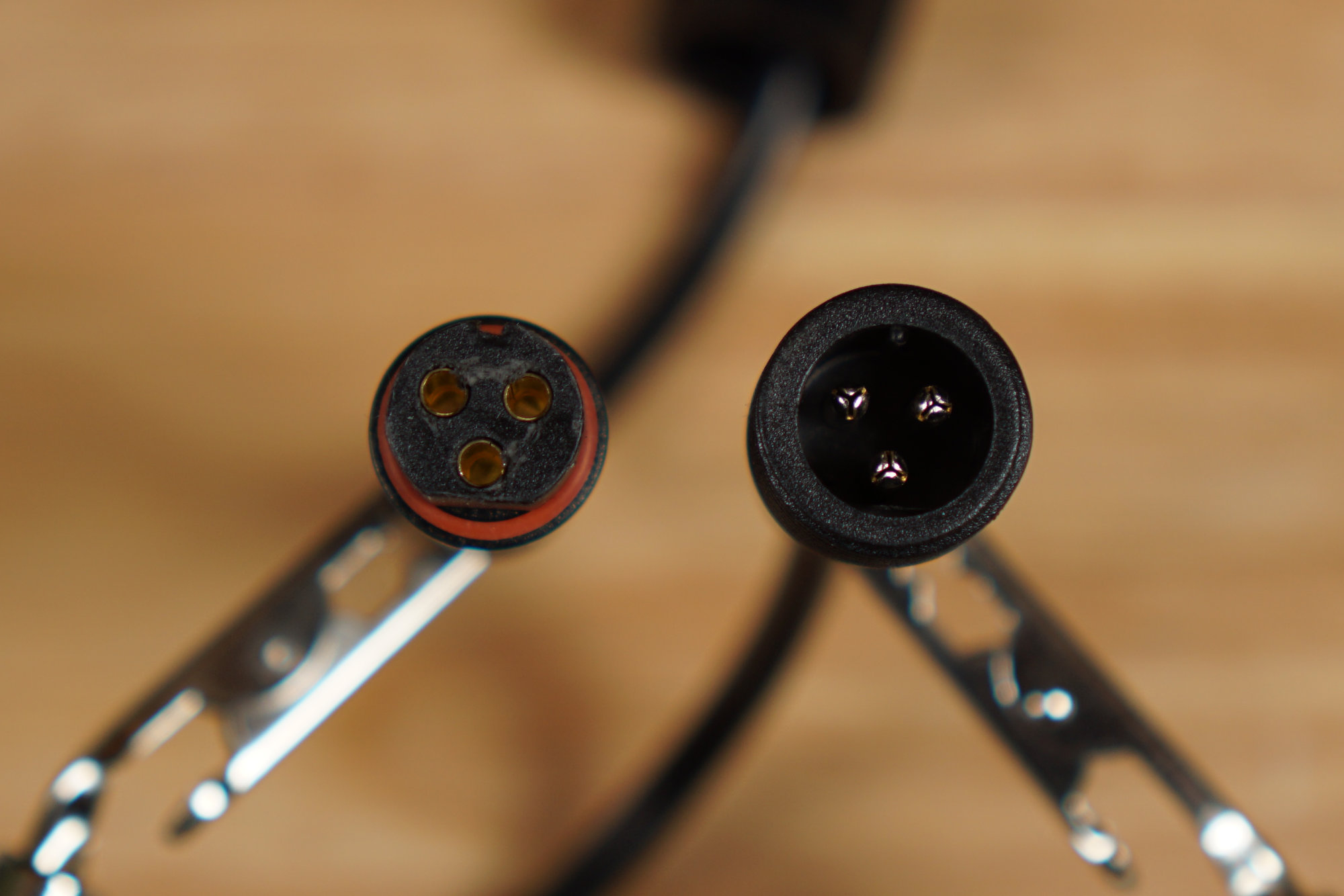
Female controller connector on the left, male light string connector on the right.
The power data supply connects to the lights via a 3 pin round connector. These connectors are the same size as all the rest of the lights connectors but, yet again, are just different enough to not be compatible.
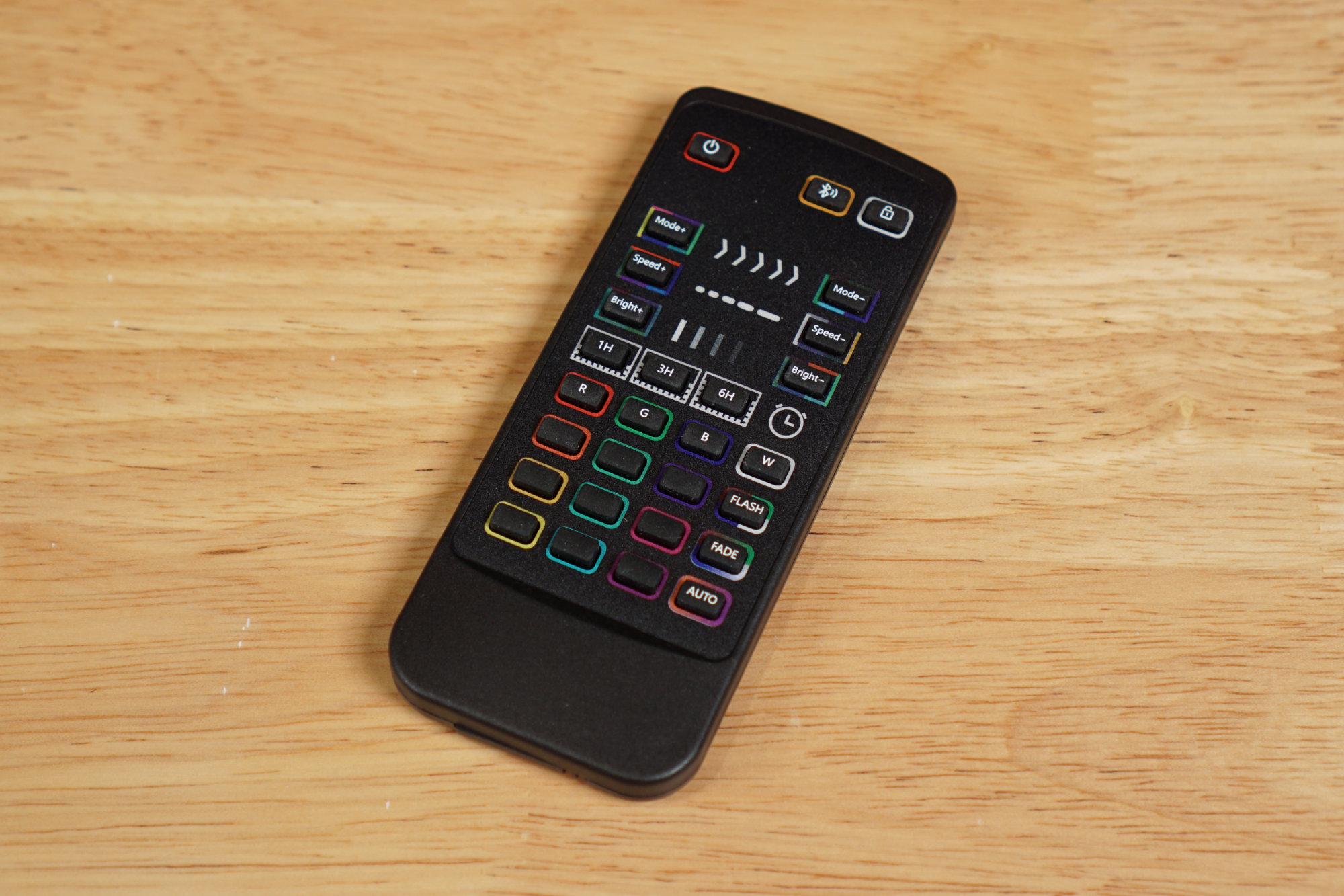
The set includes a remote control that can control some basic light settings.
The lights’ basic functionality can be controlled via the included RF remote control or, for more advanced functionality, via the Smart Life – Smart Living app by Volcano Technology Limited.
FCC Info
External photos of the model LSE-042 flood light string with an FCC ID of 2AI5T-LSE-042. This is more or less my set except it has two more lights than mine.
The FCC ID for this intentional radiator is not on the box, on the power data supply, or on any of the lights. Fortunately, the box indicates the lights are manufactured by the Shenzhen Bling Lighting Technologies CO.,LTD. Looking them up, they have a grantee code of 2AI5T. The full FCC ID for these lights should then be the grantee code and model number or 2AI5T-LSE-048-W3.
Unfortunately, that FCC ID does not exist. The closest matching ID is 2AI5T-LSE-042. The external photos for the power data supply and lights are a match other than the number of lights. The database entry for the larger -042 model includes a Model Difference letter covering any model with model number formatted as LSE-XXX-YY. The 2AI5T-LSE-042 certification therefore should cover these lights.
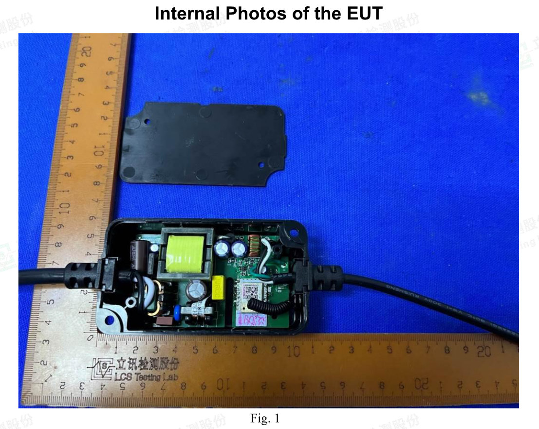
The insides of the power data supply.
From the internal photos, the power data supply includes a switching power supply and a wireless module. The wireless module is a C-Chip CC8000. It also looks like we have another white/green/black wire combination rather than the usual red/white/black wire combination.
Protocol
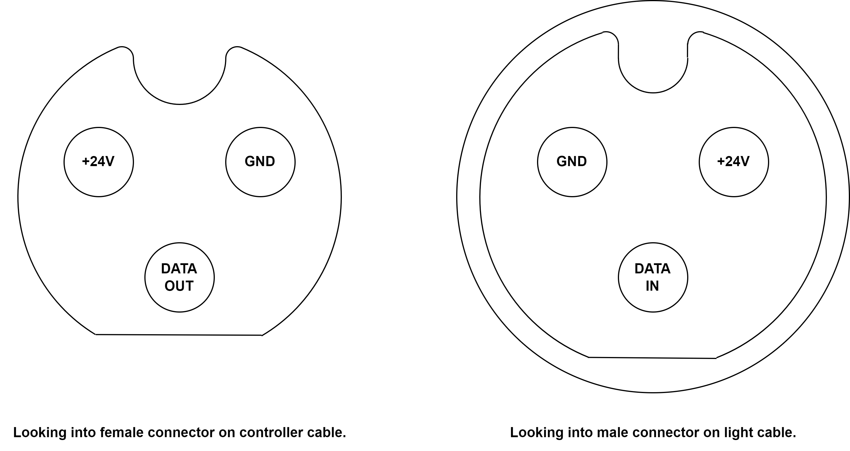
The pinout of the connectors is shown above. On the left is the pinout viewed looking into the female connector on the controller cable. On the right is the pinout viewed looking into the male connector on the light cable.
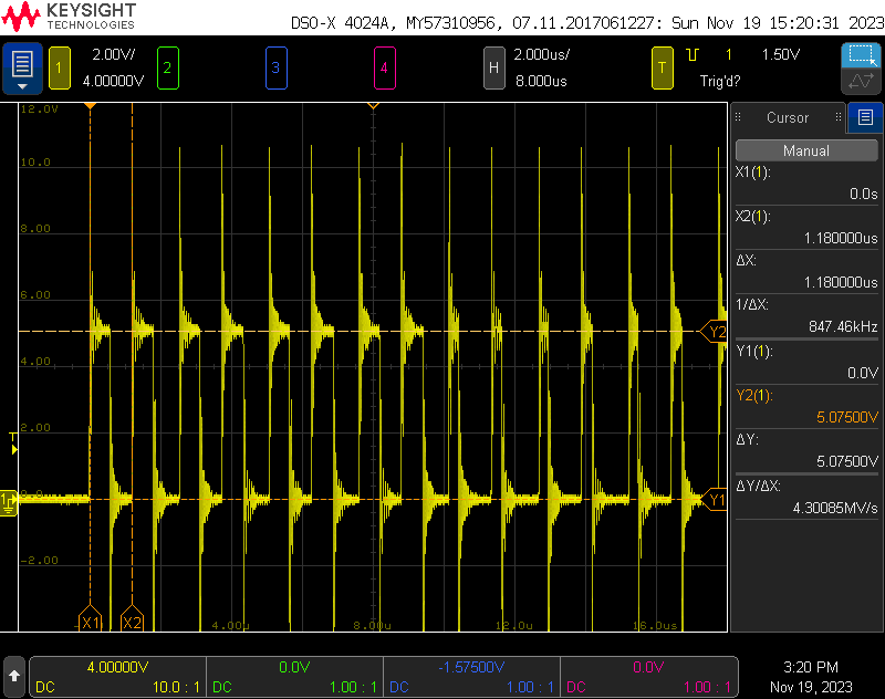
I hooked the ground and data pins on the power data supply cable to an oscilloscope. The waveform was the WS2811 protocol at 850 kHz and using 5 V logic levels. Each light had 32 bits of control information. The transmission order was 8 bits of red, 8 bits of green, 8 bits of blue, and 8 bits of warm white. This was repeated once for each light on the string.
Controlling with WLED
Hardware Connections
Black, green, and white wires again this time but in a different order!
I cut the light cable off the controller and pulled back the outer jacket to reveal white, green, and black wires instead of the usual red, white, and black wires. I used a DMM and scope to find the power, data, and ground wires. For this set of lights, the black wire was +24 V, the green wire was data, and the white wire was ground.
WLED Configuration
WLED LED and sync interface configuration panels for these lights.
To use these lights with WLED, the closest matching pixel type is SK6812 RGBW with RGB color ordering. Selecting this pixel type and color ordering in the LED Preferences panel will permit the lights to use all of WLED’s built-in effects. To control these lights over the network, be sure to select Multi RGBW from the Sync Interfaces panel to match the RGBW pixel type.
Verdict
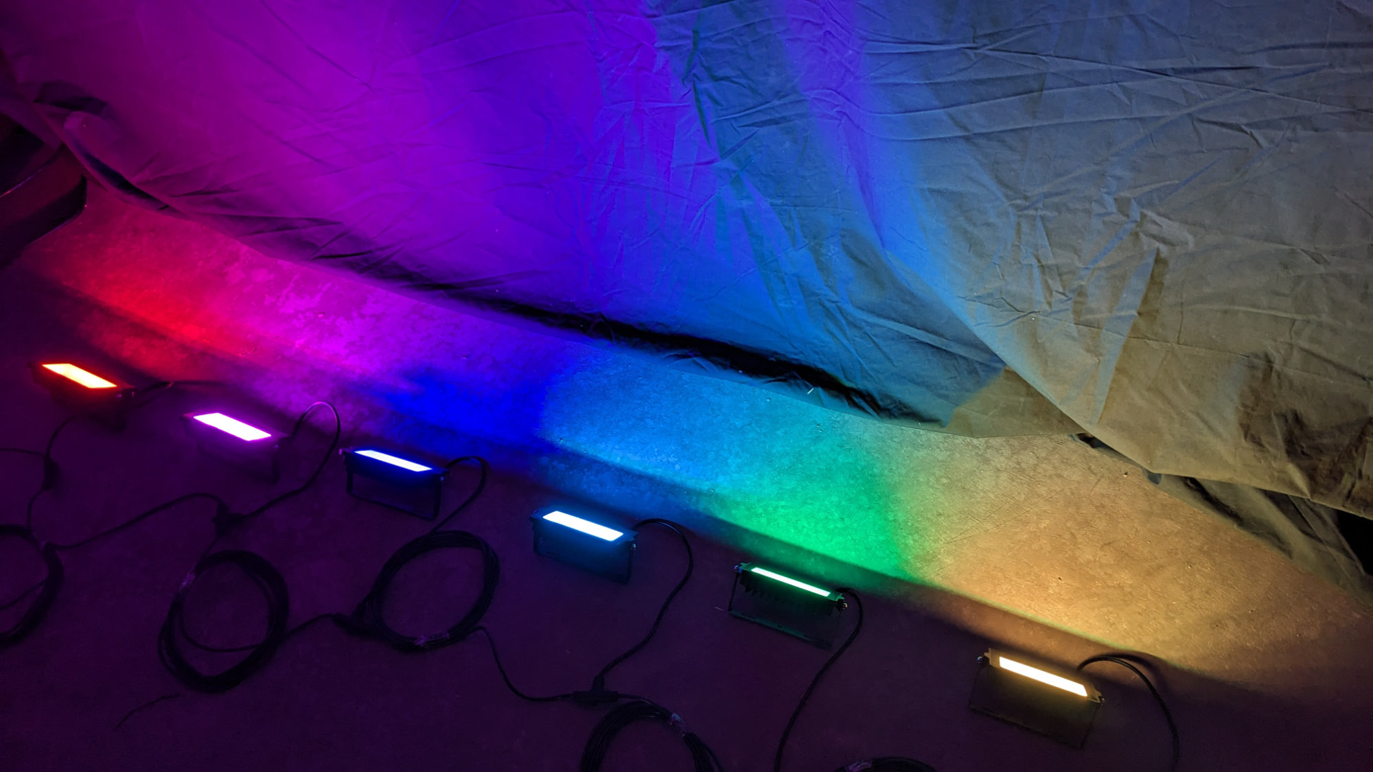
Enjoy this photo of the lights set up on the basement floor.
With these lights, all WLED features including the large selection of built-in effects are available and the pixels are controllable through both the web interface and over the network. Of all the sets examined, these are likely the best lights for lighting up large surfaces like a fence or the sides of a house. If I were to use them to light up a facade, I’d place them about every 4 to 6 feet.
Quick Update: Govee LED Flood Lights and Spot Lights
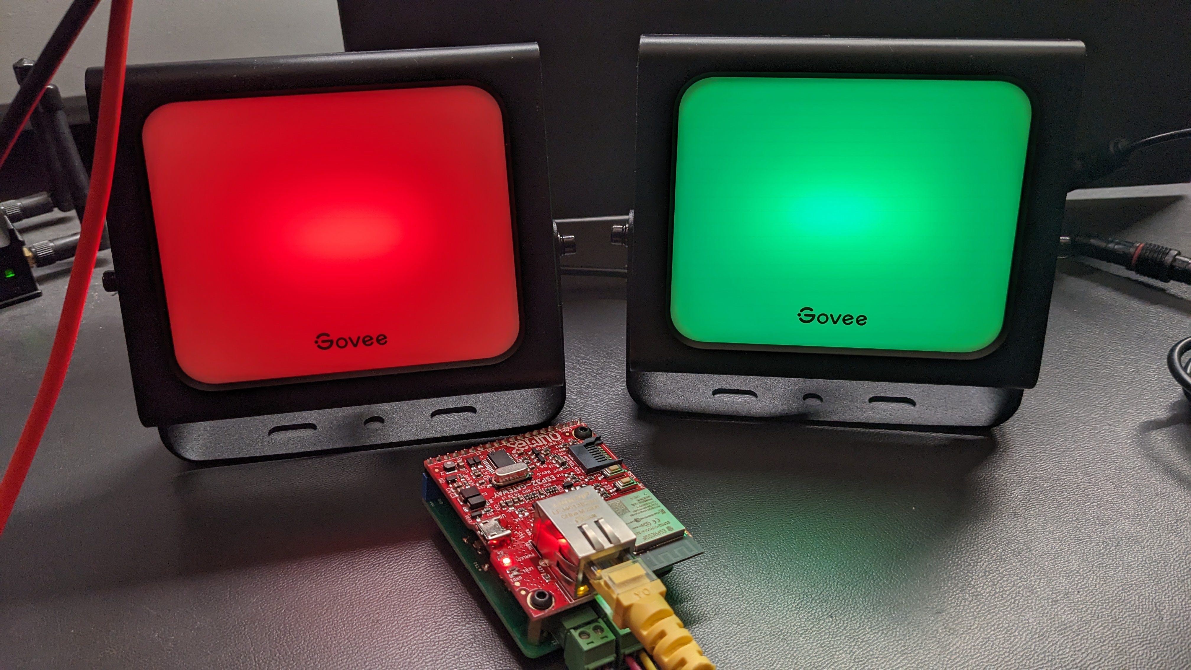
A set of 2 Govee outdoor LED flood lights controlled by WLED over the network using E1.31.
Update on another two sets of inexpensive LED lights: Both the set of 2 Govee outdoor flood lights and the set of 2 Govee outdoor spot lights use the WS2811 protocol.
scope
In the case of both the floods and the spots, it’s 750 kHz, 5 V logic, and 2 lights of 6 channels each. Each channel is 8 bits and the channel ordering is { warm white, cool white, empty, green, red, blue }. The larger sets should work as well but the number of lights will need to be increased to the number of lights in the set.
A set of 2 Govee outdoor LED spot lights controlled by WLED over the network using E1.31.
Since these are 6 channel fixtures, they won’t work well with the WLED built-in effects but will work with e1.31/ArtNet/DDP if WLED is configured for multi RGB and 4 WS2811 pixels. They come with a 24 V, 1 A, 24 W AC adapter.
Summary of WLED Settings
The table below summarizes the different light sets examined, their properties, and the settings required to use them with WLED.
| Fixture Properties | WLED Configuration | |||||||
|---|---|---|---|---|---|---|---|---|
| Set | # Lights | Volts | Amps | Watts | Pixel Count | Pixel Type | Color Order | DMX Mode |
| APPECK Smart WiFi Garden Lawn Lights | 15 lights | 24 V | 1.0 A | 24 W | 15 | SK6812 RGBW | RGB | Multi RGBW |
| APPECK Low Voltage Landscape Lights (See note 1.) |
6 lights | 24 V | 1.5 A | 36 W | 20 | WS281x | RGB | Multi RGB |
| Lumary Smart Landscape Lights (See note 2.) |
6 lights | 12 V | 1.0 A | 12 W | 100 | SK6812 RGBW | RGB | Multi RGBW |
| ALFELE RGBCW Outdoor Flood Lights | 6 lights | 24 V | 1.75 A | 42 W | 6 | SK6812 RGBW | RGB | Multi RGBW |
| Govee Outdoor Flood Lights and Spot Lights (See note 3.) |
2 lights | 24 V | 1 A | 24 W | 4 | WS281x | RGB | Multi RGB |
Notes:
- The APPECK low-voltage landscape lights use 6 lights of 5 channels of 16 bits. WLED’s built-in effects cannot be used with these lights but they may be used with WLED and some 3rd party lighting control software.
- The Lumary smart landscape lights will flicker especially on the warm white channel if configured for only 6 pixels. For best results, configure WLED to send 100 pixels even though there are only 6 lights in the set.
- The set of 2 Govee LED flood lights and the set of 2 Govee LED spot lights both use 2 lights of 6 channels of 8 bits. WLED’s built-in effects cannot be used with these lights but they may be used with WLED and some 3rd party lighting control software.
What to Look for When Buying Random Cheap Lights off the Internet
Based on my experience with these four light sets, if a light set meets the following guidelines, it likely uses the WS281x control protocol and could be hacked to work with WLED:
- Look for low-voltage lights only; no line-powered lights.
- Look for an AC adapter followed by a separate controller followed by a string of lights.
- Look for lights where there’s a 3 pin connector between the AC adapter or controller and the first light on the string.
- Look for light strings where each light can be set to a different color simultaneously.
- Look for lights with an app.
Some light sets, like those from XMCOSY+, use PWM to control the brightness of their LEDs. They fit #1, #2, and #5 above but have a 5-pin connector between the controller and the light string (violates #3) and all lights must be set to the same color (violates #4). If you have a PWM-controlled light set, these are not directly controllable using WLED. They could still be hacked to be controlled using DMX and commonly available DMX to PWM decoders.
In my next blog post, we’ll take a look at a set of Ustellar flood lights that violate guidelines #2 and #3 above. Will they still be controllable using WLED hardware? Find out next time.
Disclaimer: Glen may earn compensation for sales from links on this post through affiliate programs.