
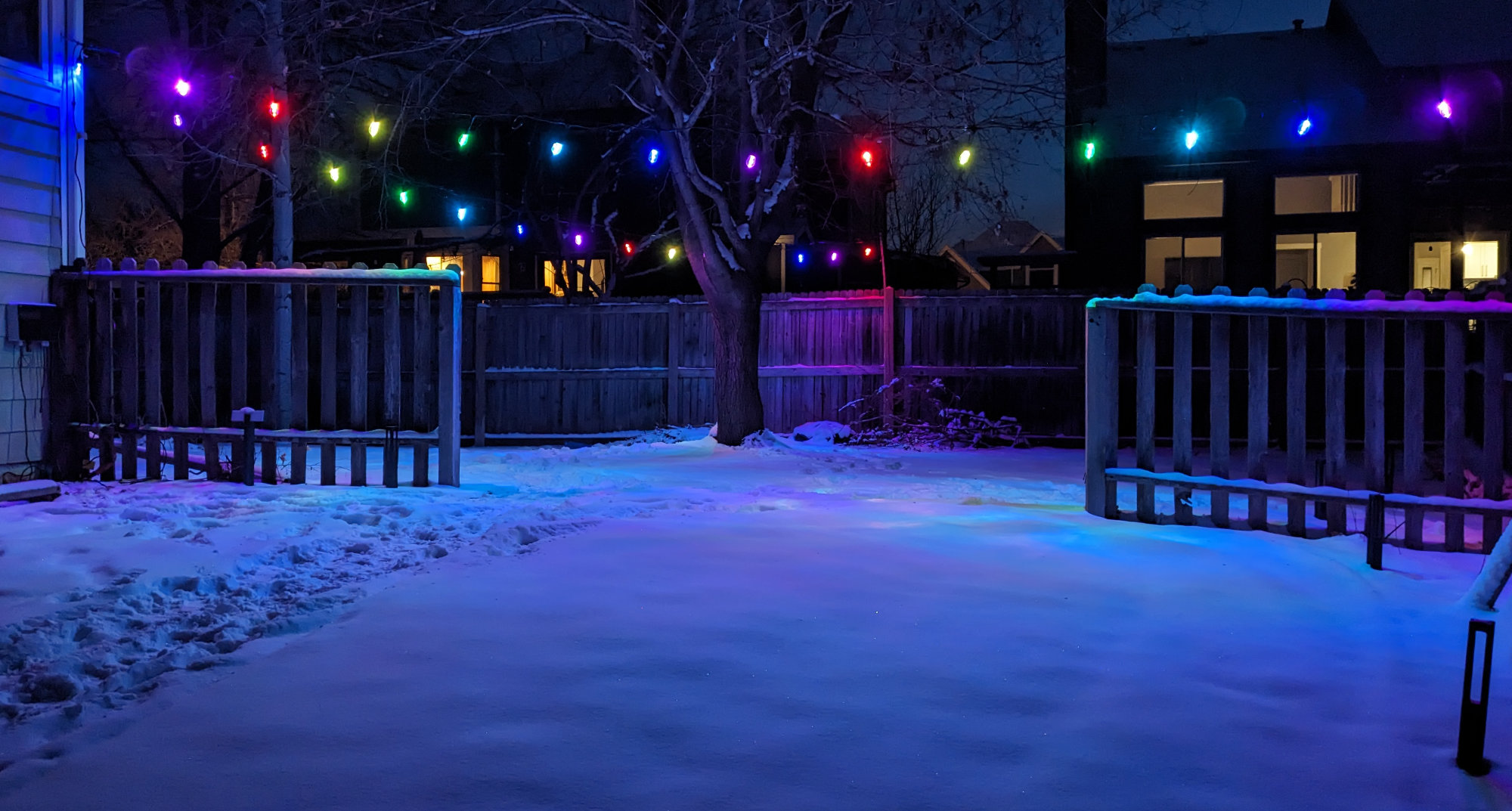
Two XMCOSY+ RGBW light strings hanging in my backyard over my snow-covered lawn.
Two years ago, I hung a set of generic G50 RGB globe lights in the backyard. They weren’t exactly waterproof and the individual lights became water logged and started acting erratically. This year, I replaced them with two sets of XMCOSY+ RGBW Patio String Lights. The new XMCOSY lights look great and I like that there’s real white LEDs in them so they can provide both decoration and functional illumination for my backyard. Read on to find out more about the installation, the lights, controlling them with WLED, and, new to me, controlling them locally with TinyTuya.
Disclaimer: Glen may earn compensation for sales from links on this post through affiliate programs.
Mechanics of the Install
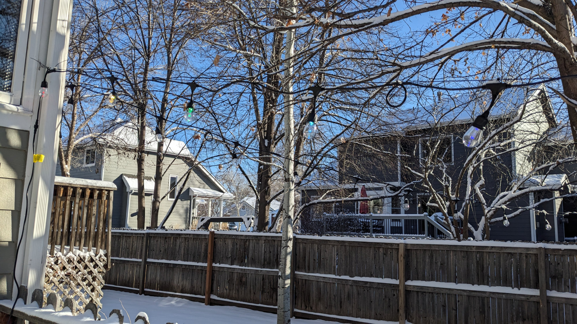
The two strings of light radiate outward from a corner of my house to the fence line.
The original lights were hung using a Newleray String Light Hanging Kit. This kit contains everything needed to suspend a set of string lights between two points including brackets, carabiner clips, clamps, turnbuckles, screws, and nylon-coated cable. The diagram below shows a typical use of the kit.
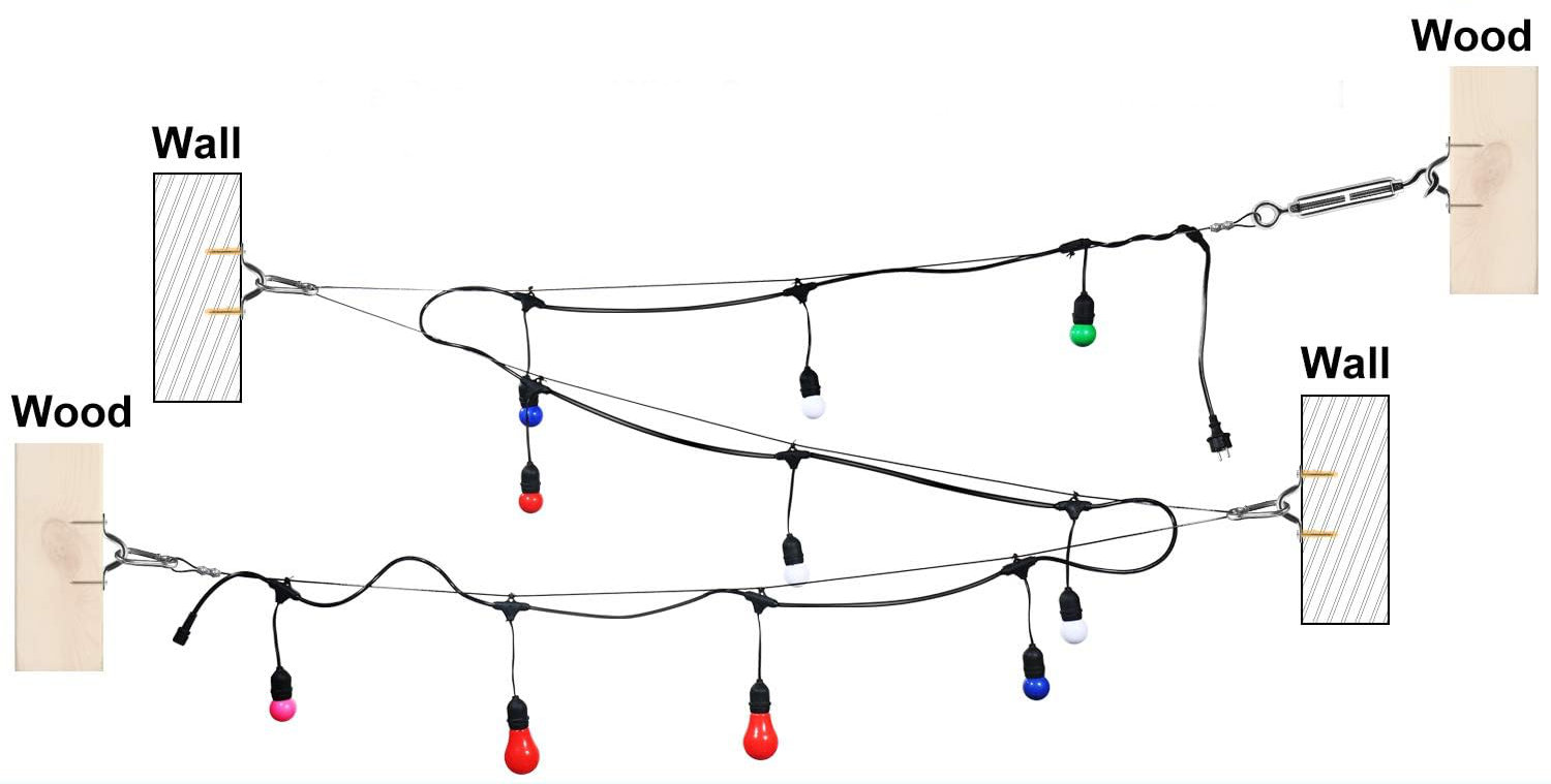
Diagram demonstrating how to use the contents of the string light hanging kit from the manufacturer’s description.
Two years ago, I hung two runs of the nylon-coated cable from a corner of the house to the fence at a 60° angle and suspended the lights from the cable using zip ties. This arrangement takes the weight of the lights off their power conductors. It also made it fairly trivial to remove the old lights by cutting their zip ties and to hang the new lights in their place with new zip ties.
Clamp and carabiner on the fence side with the new string lights attached.
On the fence side, I screwed a small board into the side of a fence post and attached the fixed end of the cable about 8 feet off the ground using a clamp, carabiner clip, and bracket as shown in the photo above.
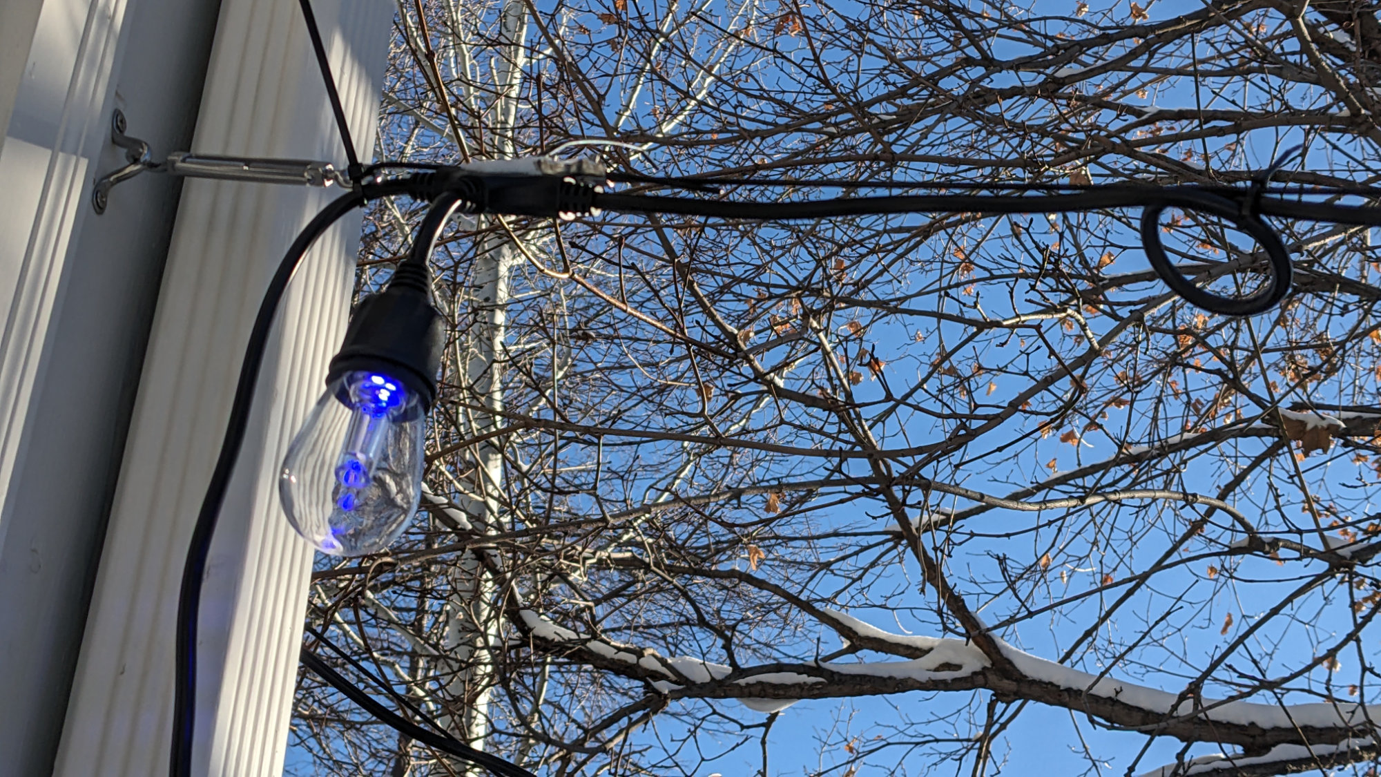
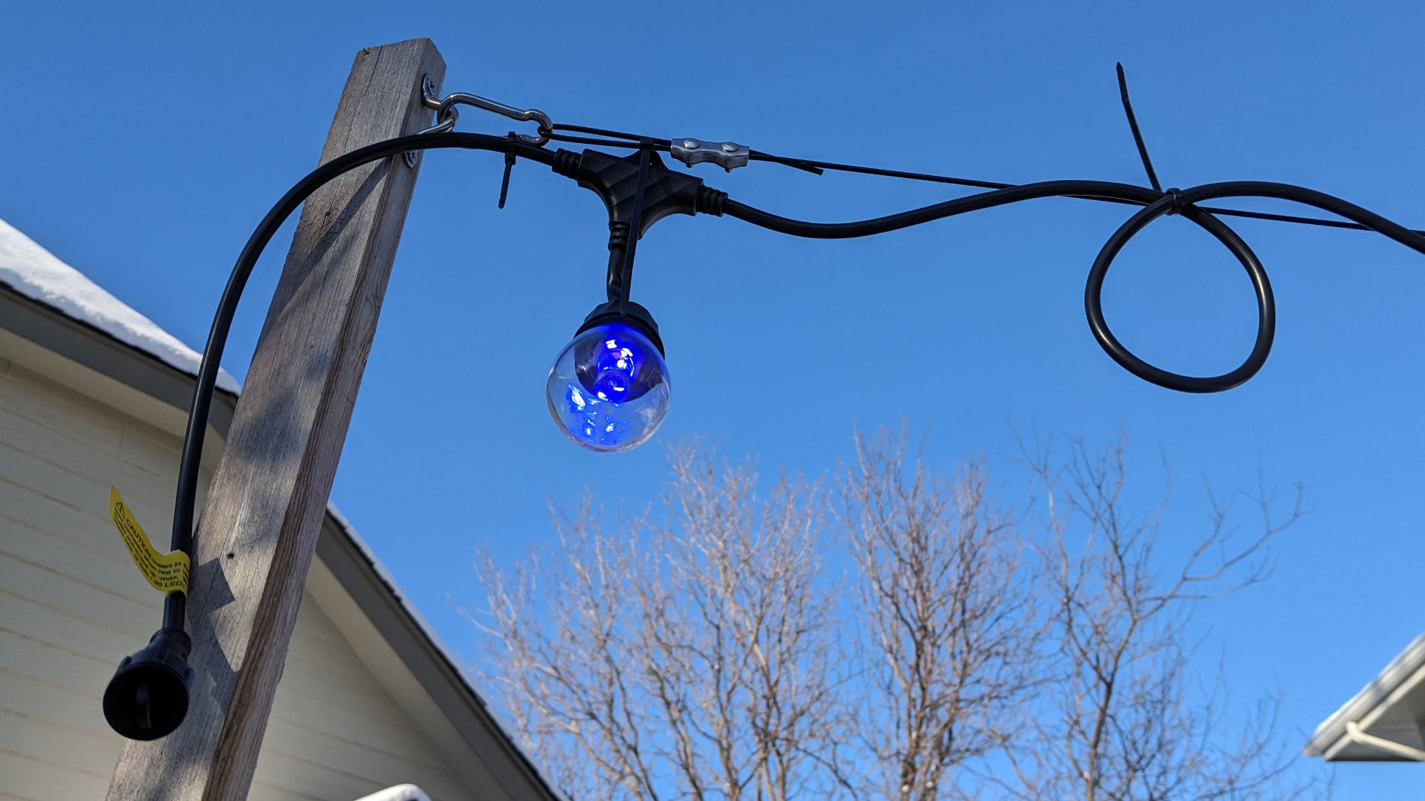
Clamp and turnbuckle on the house side with the new string lights attached. The clamp is hidden behind the bulb.
On the house side, I attached the other end of the cable to the house using a cable clamp, turnbuckle, and bracket as shown in the photo above. I then repeated this setup from the house to another segment of the fence. Each bulb was hung with a zip tie from the nylon-coated wire.
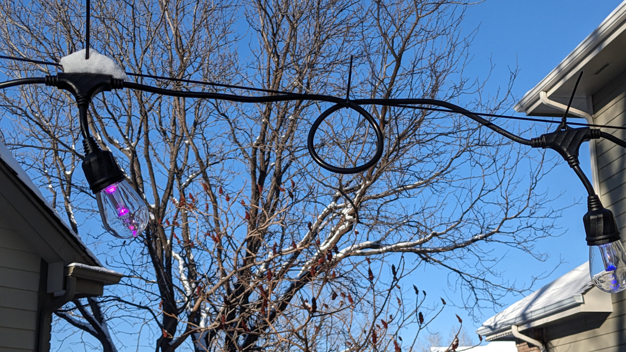
The lights hang from the nylon-coated wire using zip ties. I coiled up the excess cable between each light and zip tied those in place too.
The strings I purchased are advertised as 49 feet long with 15 RGBW S14 bulbs. The 49 feet includes the power supply leads, lead in to the first lamp, lead out from the last lamp, and the actual distance between the lamps. The spacing between each bulb is about 80 cm or 2.62 feet so there’s about 11.2 m or 36.7 feet of cable between the first bulb and the last bulb.
Since my runs are about 30 feet each and I wanted to use all 15 bulbs on each run, I had some excess wire between each lamp. I made neat coils between each lamp with the excess wire and zip tied them in place to the nylon-coated hanging wire. It’s been pretty cold outside so the wire isn’t very flexible. I’ll revisit the installation in the late spring or summer when the wire is more flexible and straighten everything out a better.
Detailed Description
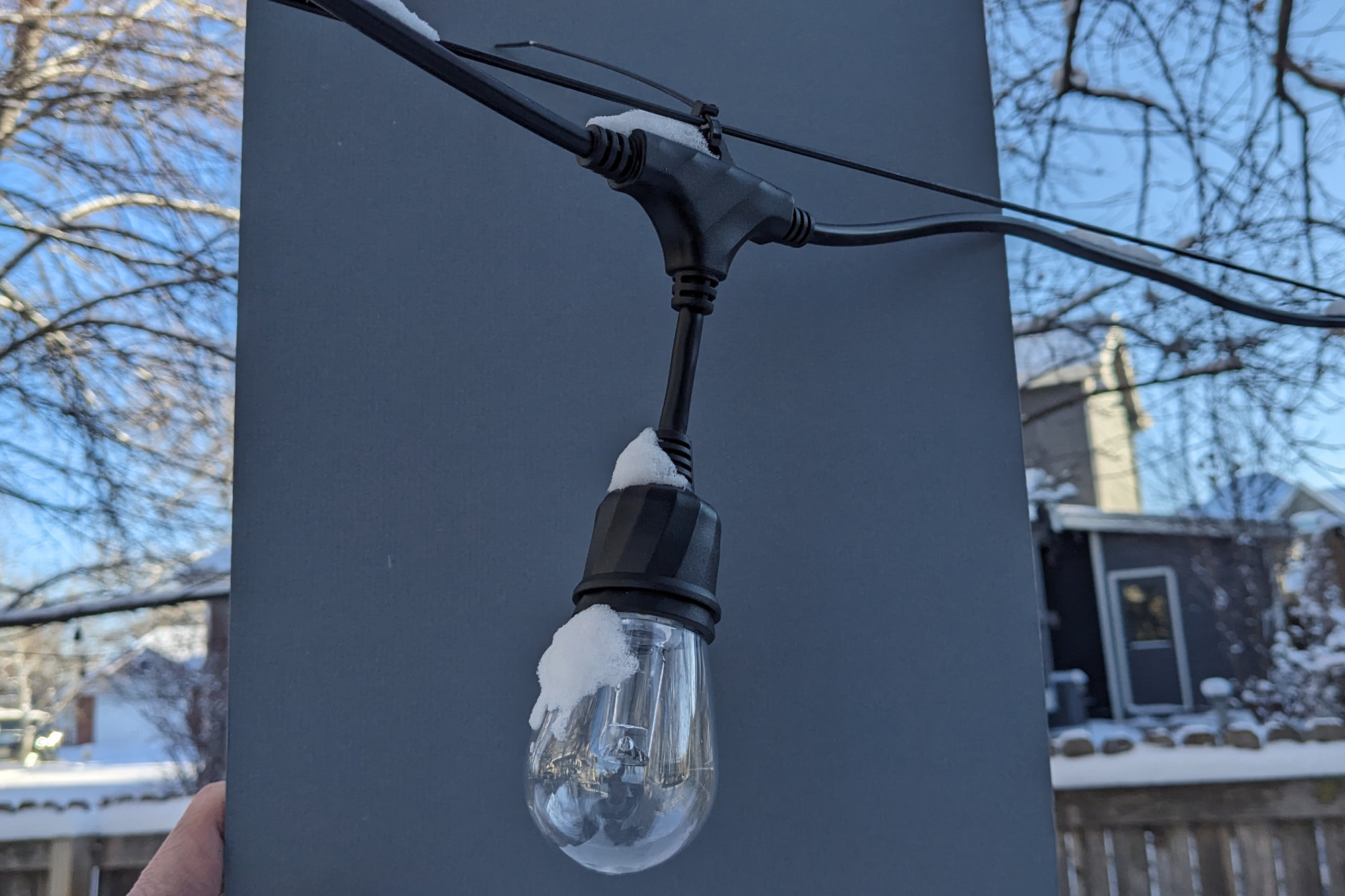
1 of the 15 bulbs on each strand.
Each bulb is suspended by a short length of wire from a T in the main power cable. The T has a small loop at the top to hang it from a hook or zip tie. The bulbs themselves are clear plastic S14-style bulbs. Each bulb is about 1.75″ in diameter and about 3.25″ long including the black plastic base.
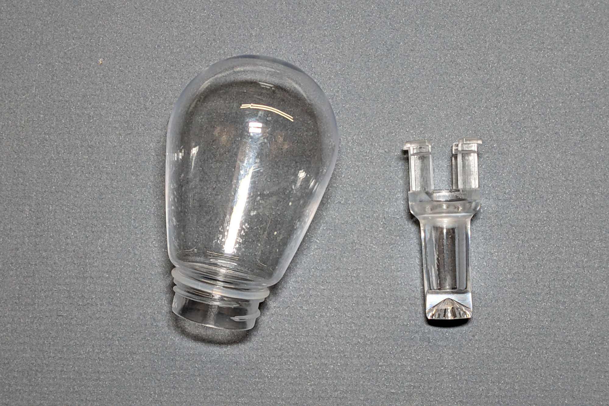
Clear outer plastic shell and inner acrylic diffuser.
The clear plastic outer shell can be unscrewed to examine the inner acrylic diffuser and circuit board. The LEDs shine from above on to the cone at the bottom of the diffuser and the cone reflects the light outward. This makes the light glow similar to the filament in an incandescent bulb. The ability to remove the outer shell will also likely be useful for draining any water ingress during spring monsoon season. We shall see.
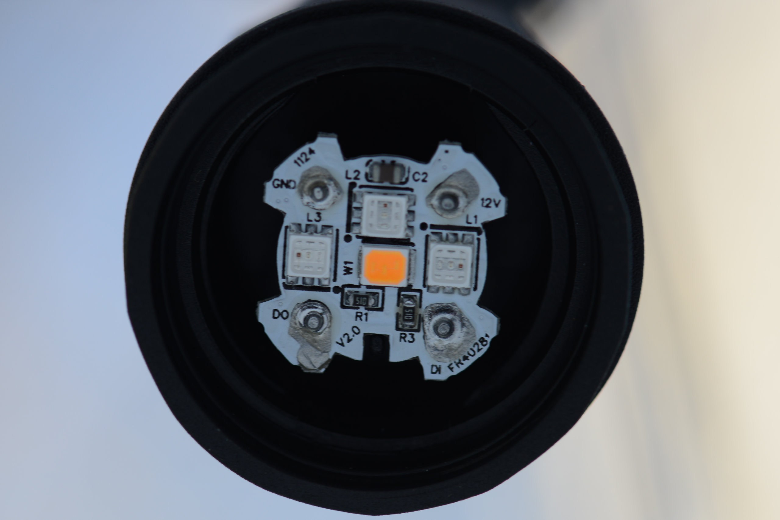
Each lamp contains 3 RGB LEDs and 1 warm white LED. The legs on the diffuser fit into the cutouts on the sides of the circuit board.
The circuit board has three small RGB LEDs and one large warm white LED. On the board are soldered connections for power, ground, data in, and data out. Since the boards are soldered in place to their wires, a repair / swap of a circuit board between lamps is likely very difficult. I can’t see a controller IC but I suspect there’s a WS2814 or similar on the back side of the circuit board since each light can be set to a different color independent of the others.
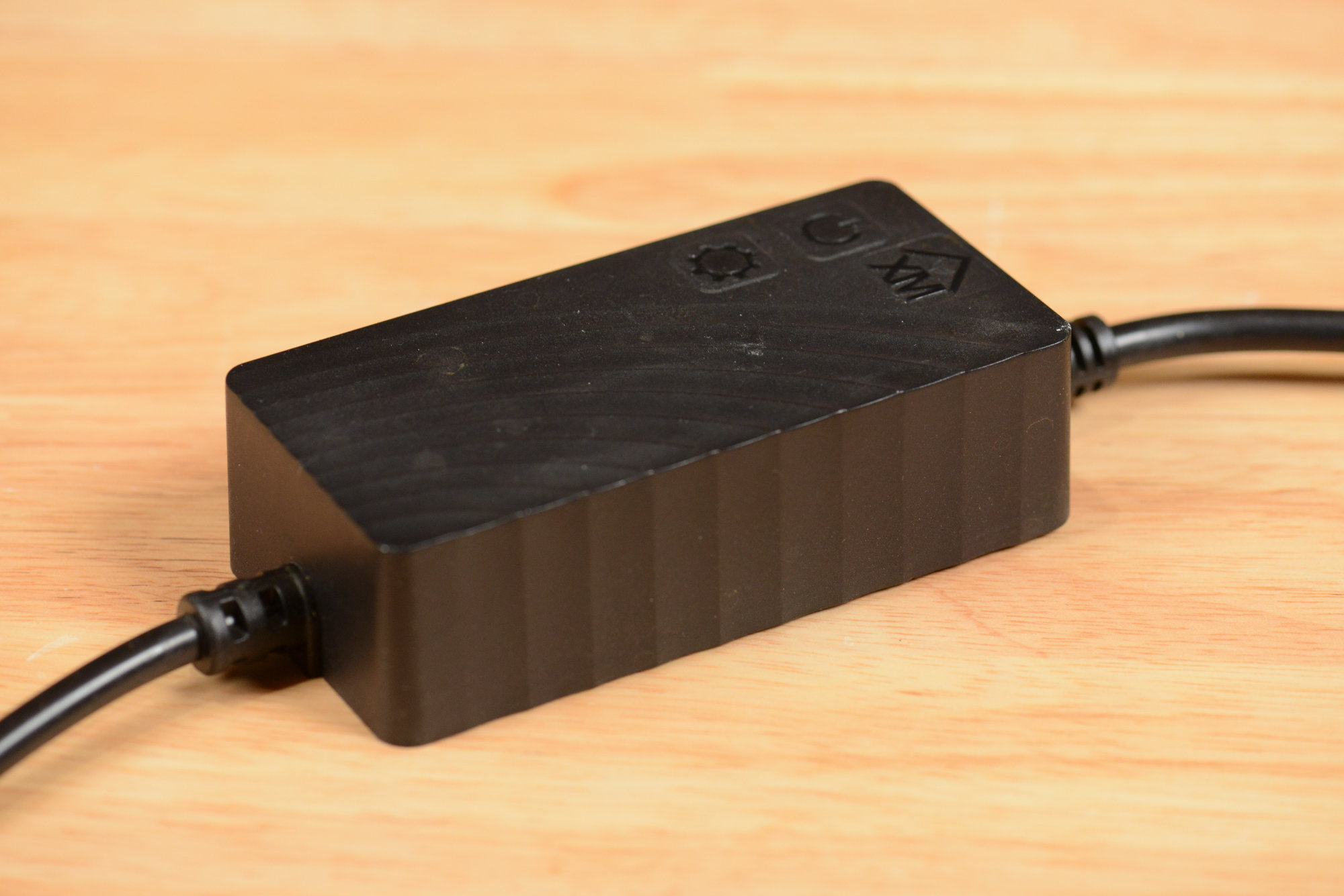
The power supply and wireless controller are a single integrated unit. There are two touch sensitive buttons on top of the supply.
The power data supply is shown in the photo above. The AC line cord is on the left and the power/data cable to the lights is on the right. The power/data cable connects to the first light in the string using a waterproof 3-pin connector. The power supply is rated for 12 V at 3 A or 36 W.
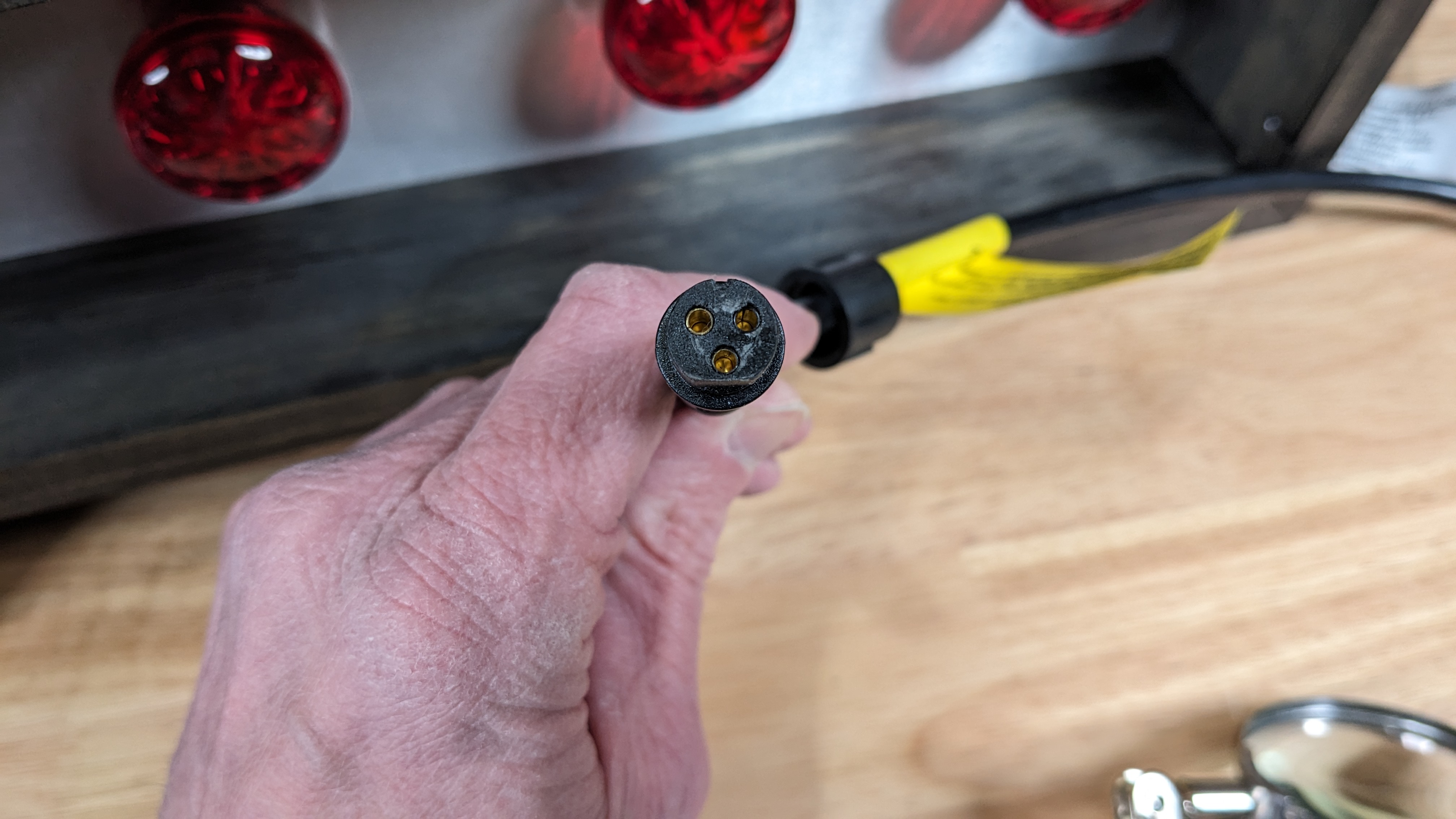
The female connector on the cable from the power supply.
The power data supply connects to the lights via a 3 pin round connector. The connector has both a knotch and a flat for polarity.
Tuya Smart Life App
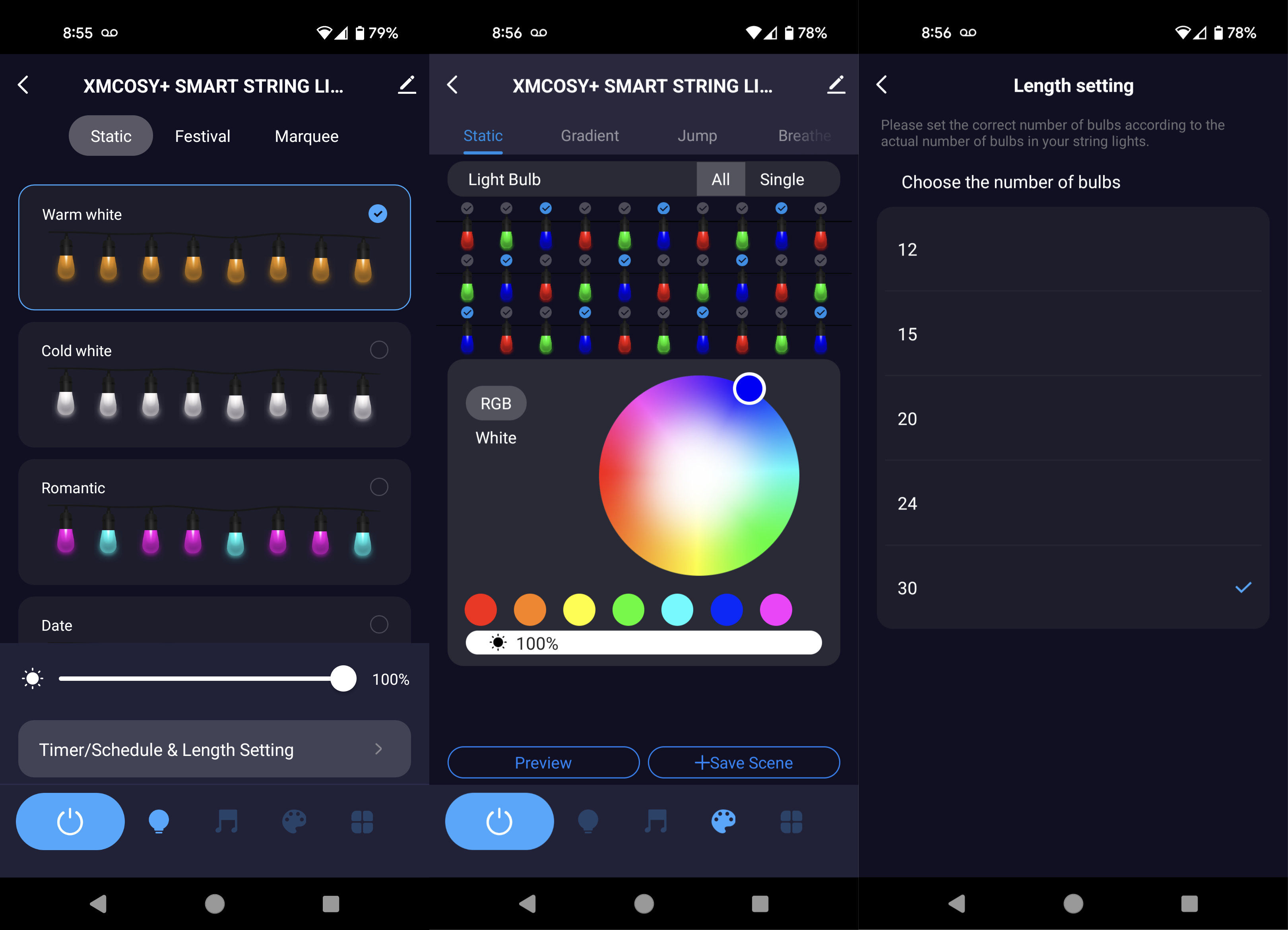
Three different screens from the Tuya Smart Life app.
These string lights are based on a Tuya IoT processor and as such can be controlled via the Tuya Smart Life app. Three screens from the app are shown in the image above. The leftmost screen shows the main screen of the app. From this screen, the lights can be set to various preprogrammed scenes. Some scenes have static colors while others have dynamic effects.
The middle screen is the DIY section of the app where you can construct new scenes and program all the lamps to be different colors. In this screen, I’ve set the first bulb to red, the second to green, the third to blue, etc., and repeated this pattern to the end of the string. When I hit the preview button, the lights will change to the set colors. From there, the set pattern can be added to a scene.
The last screen is the settings screen where you set the number of bulbs in the light string. It defaults to 30 even though each string only has 15 bulbs. If you connect two of the strings end-to-end and some of the bulbs don’t change colors, make sure this is set to 30 on this screen.
All in all, I think the app is adequate for most people’s needs. I intend to use the Smart Life app most of the time with these lights but was interested in being able to control them from crontab and a Python script. This can be done either officially through the Tuya IoT cloud developer API’s, or unofficially, locally using the TinyTuya Python library. More on that near the end of this post.
FCC Info
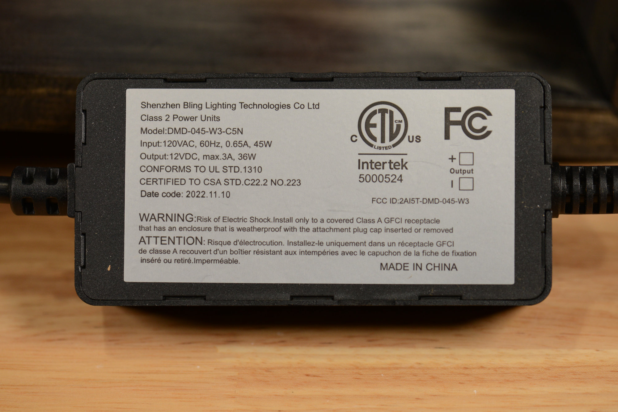
Manufacturer’s label on the back of the power supply / controller.
The FCC ID of the product is 2AI5T-DMD-045-W3 and the light is manufactured by the Shenzhen Bling Lighting Technologies Co., Ltd.
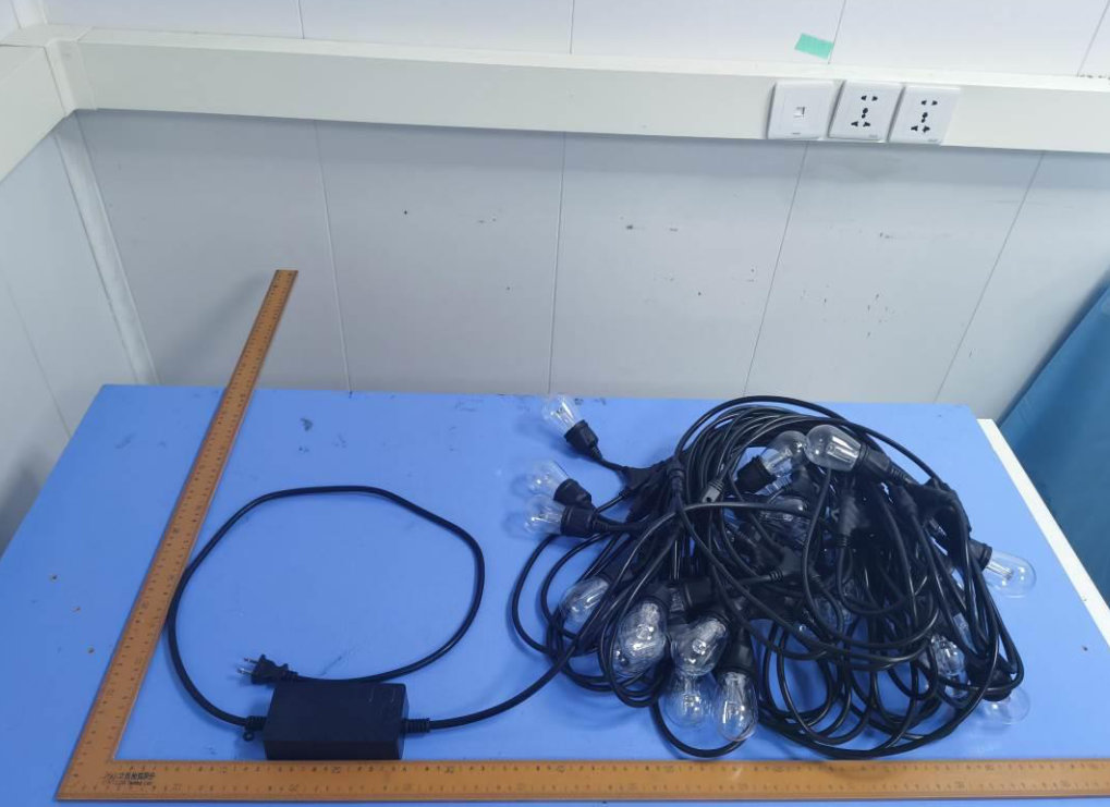
External photo of the light string from the manufacturer’s FCC test data.
I headed over to fccid.io and looked up the FCC ID. Yep, that’s an external photo of the light string and its power supply / controller.
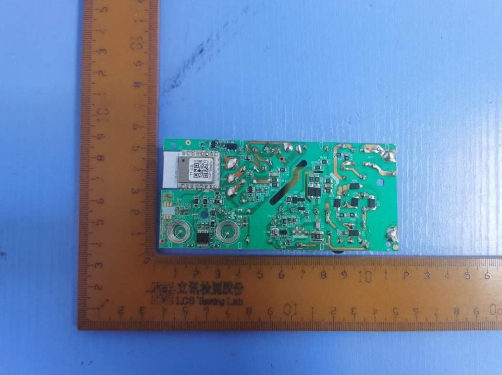
internal photo of the light string’s power supply and controller from the manufacturer’s FCC test data.
Next I opened up the PDF with the internal photos. On the other side of the board is a typical switching power supply. On this side of the board, you can see the wireless module, the two touch sensitive buttons, and, most impressively, the very nice isolation between the high voltage and low voltage ends of the PCB! I suspect the wireless module is a C-Chip CC8000 but can’t make out enough detail to confirm.
Protocol Information
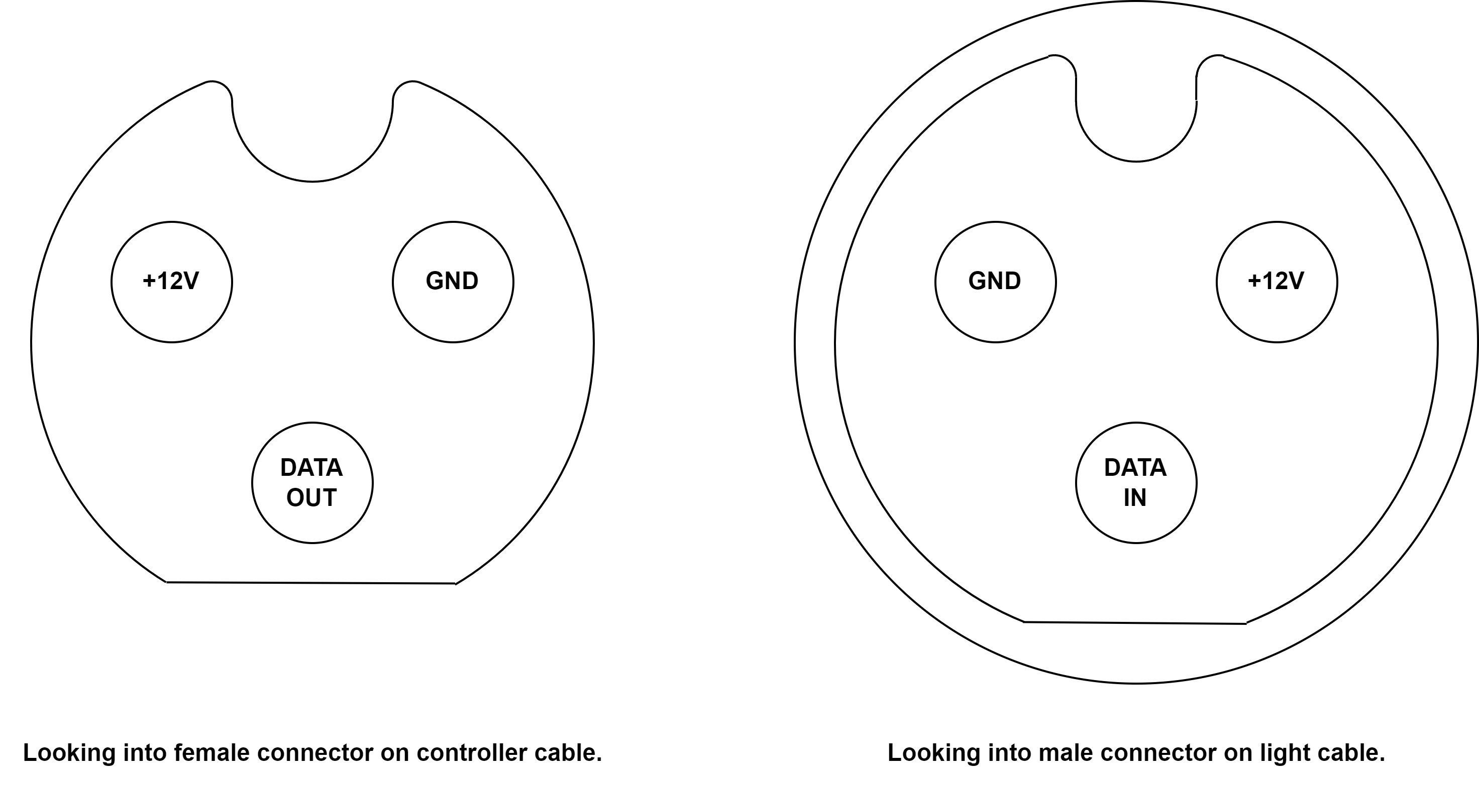
Pinouts drawn looking into the connectors.
The pinout of the connectors is shown above. On the left is the pinout viewed looking into the female connector on the controller cable. On the right is the pinout viewed looking into the male connector on the light cable.
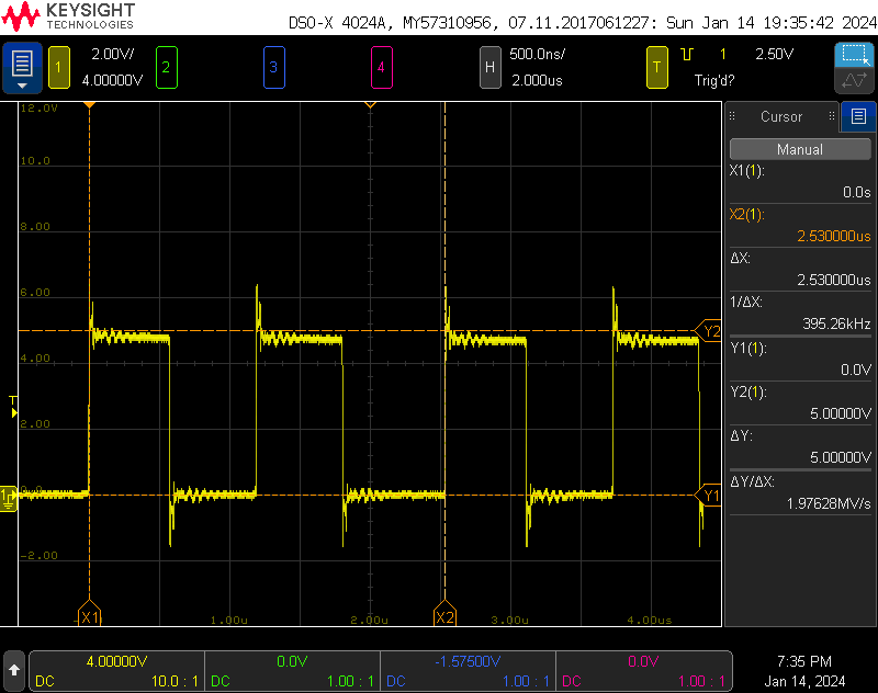
In every pair of transmitted data bits, the first bit is slightly shorter than the second bit.
I hooked the ground and data pins on the power data supply cable to an oscilloscope. The waveform was the WS2811 protocol at 800 kHz and using 5 V logic levels. Each light had 32 bits of control information. The transmission order was 8 bits of red, 8 bits of green, 8 bits of blue, and 8 bits of warm white.
I did notice that the first bit in every pair of transmitted data bits was slightly shorter than the second bit. You can see this between the X1 and X2 cursors in the scope capture above. The first bit of every pair is about 1.2 μs and the second bit is 1.3 μs for an average bit time of 1.25 μs.
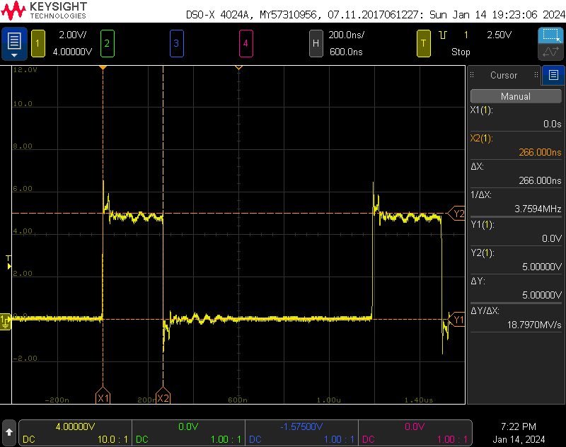
Transmission of a zero bit.
The scope screenshot above shows the transmission of a zero bit. The high time is 266 ns which is within the WS2814 datasheet’s spec of 220 ns to 380 ns. The low time is 934 ns which is also within the WS2814 datasheet’s spec of 580 ns to 1000 ns.
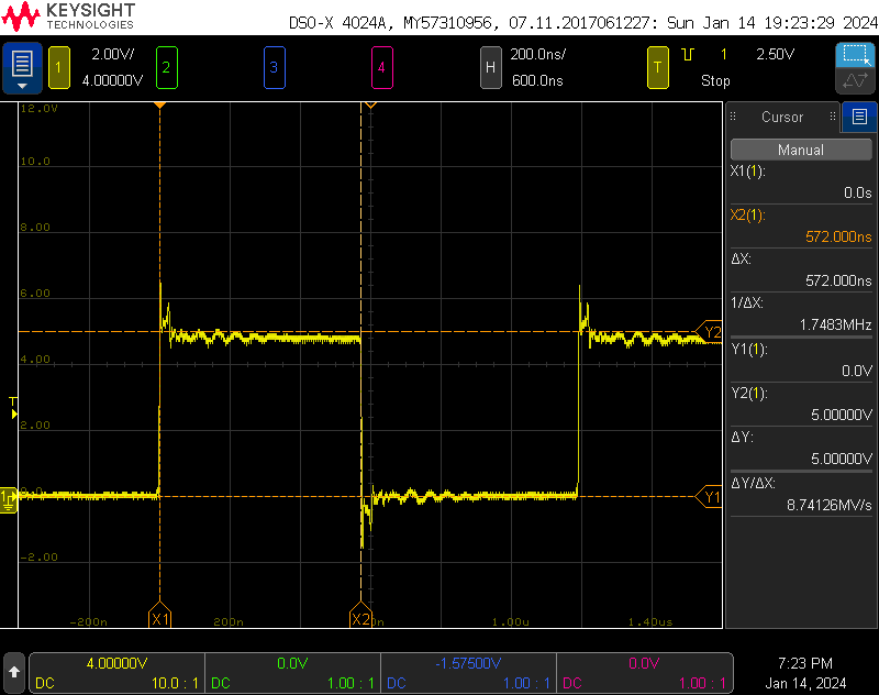
Transmission of a one bit. That high time is a bit sus.
The scope screenshot above shows the transmission of a one bit. The high time is 572 ns which is just shy of the WS2814 datasheet’s spec of 580 ns to 1000 ns. The low time is 628 ns which is within the WS2814 datasheet’s spec of 580 ns to 1000 ns. Despite the high bit time being a bit short, it still seems to work fine. It could be a different chip than a WS2814 too.
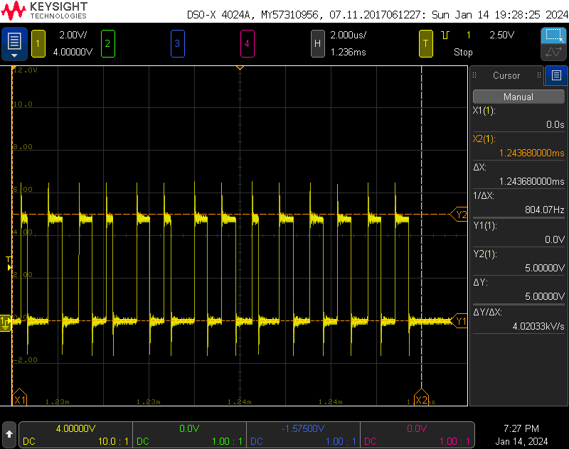
The last few bits.
The total time to send a frame of pixel data is 1.24368 ms with 30 lights enabled in the app. This corresponds to 31 lights of 4 channels each with 8 bits per channel. That’s one extra “dummy” light that’s transmitted in every frame.
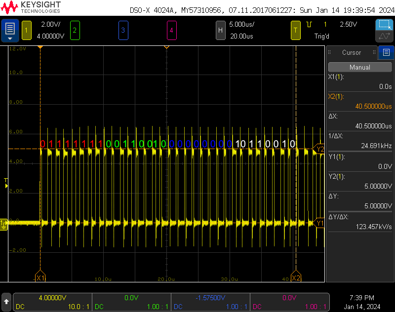
Warm white as selected from the main scene screen in the app.
While I had the scope out, I was curious what RGBW levels were used for warm white and cool white. I selected each of these colors of white light using the main scene screen in the app, captured the transmitted RGBW levels on the scope, and annotated the captures. Warm white is shown in the capture above. This is an RGBW value of (0x7F, 0x32, 0x00, 0xB2). That’s mid red, a bit of green, no blue, and a lot of white.
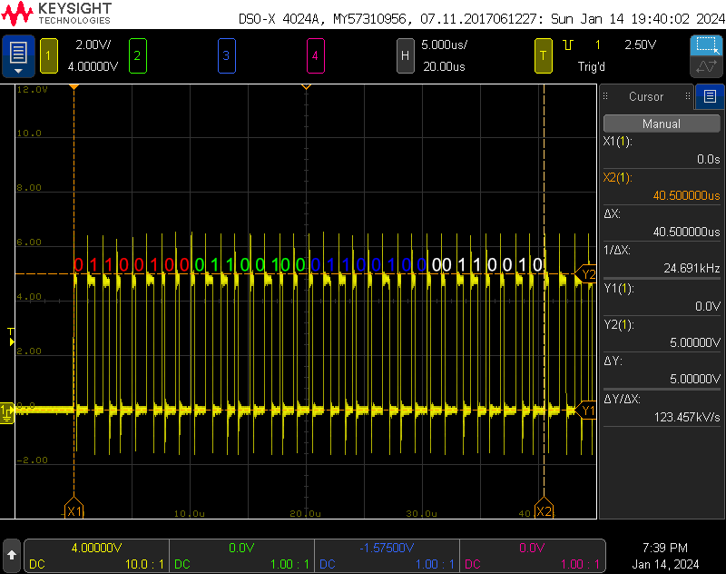
Cool white as selected from the main scene screen in the app.
And cool white is shown in the capture above. This is an RGBW value of (0x64, 0x64, 0x64, 0x32). That’s equal parts red, green, and blue and half white. To make warm white, the controller is mixing the warm white LED with some red and green. To make cool white, the controller is mixing a bit of warm white into a brighter composite white made from the red, green, and blue LEDs.
Controlling with WLED / FastLED
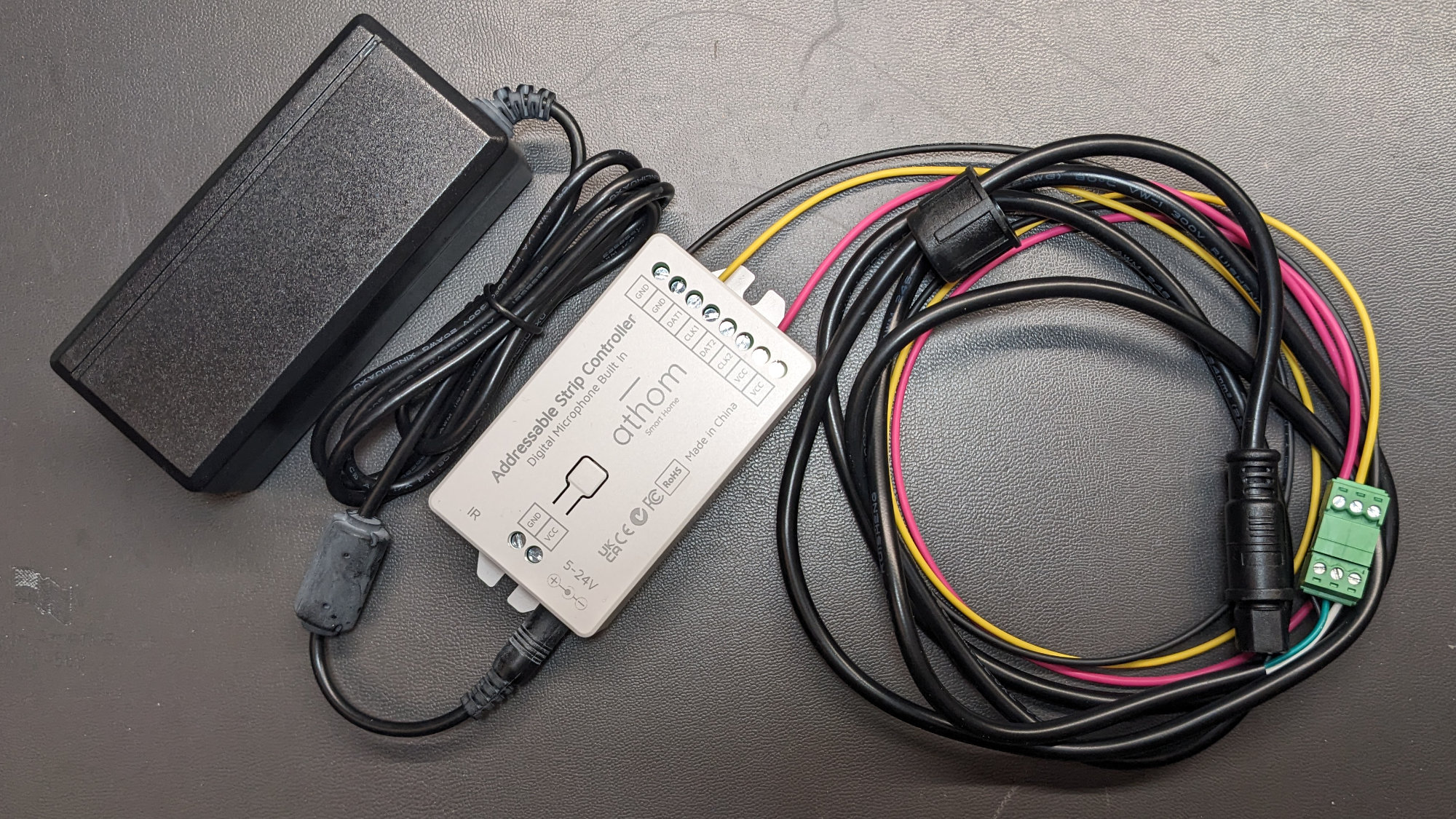
Preparing to test the light string with a 12 V, 3 A desktop power supply and an Athom Tech WLED controller.
I haven’t tried it because it’s been -11°F outside all weekend, but these lights should be 100% usable through WLED by connecting them to your favorite 12 V-capable WLED controller hardware. Both the bulit-in effects and E1.31/Art-Net/DDP streaming should work.
Update: The temperature is almost 60°F warmer this weekend than last weekend and I was able to go outside and test one of the light strings with WLED running on an Athom Tech WLED controller. The Athom controller uses an ESP32 and comes preloaded with a custom version of WLED that works with their IR and RF remotes. I did not try an OTA update but the firmware can be updated or replaced by snapping the back cover off and connecting a 3.3V USB-to-serial cable to the serial port pads inside.
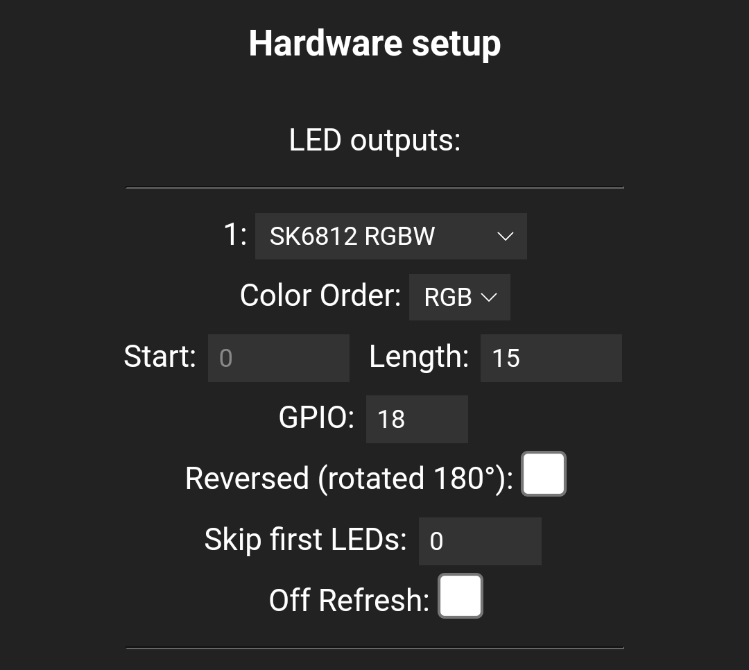
WLED LED configuration for use with one string of 15 lights.
The LED settings I used with a single string of 15 lights are shown in the snippet above from WLED’s LED Preferences screen. I set the LED type to SK6812 and the color order to RGB. With a string of 15 lights, setting the number of LEDs to 15 worked. No extra dummy LED was needed after the 15 real LEDs. To use WLED and the light string with E1.31, Art-Net, or DDP streaming, set the data type to Multi RGBW in the Sync Interfaces screen. All the WLED effects work 100% as expected with these light strings.
Controlling with TinyTuya
Describing how to get started with TinyTuya is beyond the scope of this blog post. Fortunately, the documentation and getting started guide for the library is quite good and the examples and issues pages cover most of the missing details. What I did find missing though was how to control a strip or string of multiple bulbs that all can be set to different colors independently. This information is likely specific to the XMCOSY string lights but I hope that it’s applicable and useful to people with other sets of strip or string lights too.
I went through the basic setup process for TinyTuya which required the following steps:
- Install tinytuya using pip.
- Create a Smart Life app account using the Smart Life app.
- Add the string lights to the Smart Life app and verify the app controls the lights.
- Create a Tuya IoT account.
- Link the Smart Life app account to the Tuya IoT account by scanning a QR code from the IoT account in the Smart Life app.
- Import my devices from the Smart Life app into the Tuya IoT account.
- Run tinytuya scan to get the local IP addresses of the string lights.
- Run tinytuya wizard with the IoT account keys to produce a json file with the device IDs, local device keys, and device versions that I’d need to issue local commands to my devices.
After performing all those steps, I could run the provided examples and had basic control over the string lights. It sounds like a complicated process but it’s much easier than setting up a Microsoft Azure or Amazon AWS account and doesn’t require a credit card. It took about an hour from start to having working Python scripts controlling the lights in the backyard.
The basics worked well enough but what I really wanted to do was set the colors of all the bulbs separately. Googling revealed one issue that pertained to controlling a strip of LEDs but the issue’s discussion thread ended without really reaching a resolution. I think. The thread did contain details on monitoring the traffic between the phone app and the string lights using the monitor.py script in the examples directory. I ran that script then used the diy mode in the app to set all the lamps red then green then blue. I received three messages in the monitor.py example. When I set the all the lamps to red, I received the message:
Received Payload: {'dps': {'102': 'AP8AAACAAQABAABkZAAAAQAAZGQAAAEAAGRkAAABAABkZAAAAQAAZGQAAAEAA
GRkAAABAABkZAAAAQAAZGQAAAEAAGRkAAABAABkZAAAAQAAZGQAAAEAAGRkAAABAABkZAAAAQAAZGQAAAEAAGRkAAABAABkZ
AAAAQAAZGQAAAEAAGRkAAABAABkZAAAAQAAZGQAAAEAAGRkAAABAABkZAAAAQAAZGQAAAEAAGRkAAABAABkZAAAAQAAZGQAA
AEAAGRkAAABAABkZAAAAQAAZGQAAAEAAGRkAAA='}, 't': 1705261231}
When I set the all the lamps to green, I received the message:
Received Payload: {'dps': {'102': 'AP8AAACAAQABAHhkZAAAAQB4ZGQAAAEAeGRkAAABAHhkZAAAAQB4ZGQAAAEAe
GRkAAABAHhkZAAAAQB4ZGQAAAEAeGRkAAABAHhkZAAAAQB4ZGQAAAEAeGRkAAABAHhkZAAAAQB4ZGQAAAEAeGRkAAABAHhkZ
AAAAQB4ZGQAAAEAeGRkAAABAHhkZAAAAQB4ZGQAAAEAeGRkAAABAHhkZAAAAQB4ZGQAAAEAeGRkAAABAHhkZAAAAQB4ZGQAA
AEAeGRkAAABAHhkZAAAAQB4ZGQAAAEAeGRkAAA='}, 't': 1705261260}
When I set the all the lamps to blue, I received the message:
Received Payload: {'dps': {'102': 'AP8AAACAAQABAPBkZAAAAQDwZGQAAAEA8GRkAAABAPBkZAAAAQDwZGQAAAEA8
GRkAAABAPBkZAAAAQDwZGQAAAEA8GRkAAABAPBkZAAAAQDwZGQAAAEA8GRkAAABAPBkZAAAAQDwZGQAAAEA8GRkAAABAPBkZ
AAAAQDwZGQAAAEA8GRkAAABAPBkZAAAAQDwZGQAAAEA8GRkAAABAPBkZAAAAQDwZGQAAAEA8GRkAAABAPBkZAAAAQDwZGQAA
AEA8GRkAAABAPBkZAAAAQDwZGQAAAEA8GRkAAA='}, 't': 1705261278}
The equals at the end made me think these were base 64 encoded strings so I ran them through a base64 decoder and dumped them as hex strings (one decoded string per line, truncated):
00 ff 00 00 00 80 01 00 01 00 00 64 64 00 00 01 00 00 64 64 00 00 01 00 00 64 64 00 00 ...
00 ff 00 00 00 80 01 00 01 00 78 64 64 00 00 01 00 78 64 64 00 00 01 00 78 64 64 00 00 ...
00 ff 00 00 00 80 01 00 01 00 f0 64 64 00 00 01 00 f0 64 64 00 00 01 00 f0 64 64 00 00 ...
I noticed a repeating pattern of 7 bytes after the first 8 bytes. And there were 30 of this repeating pattern of 7 bytes! And the app was set to 30 lights! Reformatting the red, green, and blue decoded strings yielded:
00 ff 00 00 00 80 01 00  01 00 00 64 64 00 00
                         01 00 00 64 64 00 00
                         01 00 00 64 64 00 00 ...

00 ff 00 00 00 80 01 00  01 00 78 64 64 00 00
                         01 00 78 64 64 00 00
                         01 00 78 64 64 00 00 ...

00 ff 00 00 00 80 01 00  01 00 f0 64 64 00 00
                         01 00 f0 64 64 00 00
                         01 00 f0 64 64 00 00 ...
That’s 8 bytes of header followed by 30 sets of 7 bytes. The third column was the only thing that changed in the messages from red to green to blue. 0x00 is 0 decimal, 0x78 is 120 decimal, and 0xf0 is 240 decimal. That’s the hue! And 0x64 is 100 decimal. That sounds like percentage for saturation and intensity. I repeated this process through different hue, saturation, and intensity settings in the app. I learned that the 7 bytes corresponded to:
| Byte | Description |
|---|---|
| 0 | Always 0x01 |
| 1 | Hue (0 to 360) MSB |
| 2 | Hue (0 to 360) LSB |
| 3 | Saturation (0 to 100) |
| 4 | Intensity (0 to 100) |
| 5 | Unknown |
| 6 | Unknown |
I then ran some captures while adjusting the color temperature of the light strings and was able to update the table:
| Byte | Description |
|---|---|
| 0 | Flag: 0x00 for CCT, 0x01 for HSI |
| 1 | HSI Hue (0 to 360) MSB |
| 2 | HSI Hue (0 to 360) LSB |
| 3 | HSI Saturation (0 to 100) |
| 4 | HSI Intensity (0 to 100) |
| 5 | CCT Color Temperature (0 (warmest) to 100 (coolest)) |
| 6 | CCT Intensity (0 to 100) |
Note that bytes 1, 2, 3, and 4 are always zero when byte 0 is 0 and bytes 5 and 6 are always zero when byte 0 is 1.
The Python script below will set the lights on the light string to the colors specified in the colors dictionary declared in __main__ at the end of the listing. Each color is specified with a tuple containing the six parameters described in the comments at the beginning of the listing. The colors will be repeated if there’s more lights on the string than colors specified in the dictionary. Don’t forget to replace the device IP, device ID, device key, and device version with the values for your light string.
# Format of the color tuple in main is
#
# ( HSI Flag, Hue, Sat, Int, CCT Temp, CCT Int )
#
# HSI Flag = 0 for CCT mixing, 1 for HSI mixing
#
# If HSI Flag is 1:
#   Hue is 0 to 359, 0 is red, 120 is green, 240 is blue
#   Sat is 0 to 100
#   Int is 0 to 100
#   CCT Temp is 0
#   CCT Int is 0
#
# If HSI Flag is 0:
#   Hue is 0
#   Sat is 0
#   Int is 0
#   CCT Temp is 0 to 100, 0 = warmest and 100 = coolest
#   CCT Int is 0 to 100
#
# When using the smart life app's diy feature to set WW, NW, or CW at 100%:
#
#   WW is   0, 100
#   NW is  50, 100
#   CW is 100, 100
#
# Hue is 2 bytes, MSB first. The rest are 1 byte each.
#

import tinytuya
import time
import base64

# replace the x's with the data for your light string, IP is the local IP, not the cloud IP
DEVICE_IP = "x.x.x.x"
DEVICE_ID = "xxxxxxxxxxxxxxxxxxxxxx"
DEVICE_KEY = "xxxxxxxxxxxxxxxx"
DEVICE_VER = 3.3

def xmcosy_string_lights_encode_colors (lights, colors, offset):

  # header is 8 bytes and always the same
  header = b'\x00\xff\x00\x00\x00\x80\x01\x00'

  # replicate the specified colors across the specified number of lights as many times as possible
  light = 0
  index = offset
  levels = []
  for light in range (lights):
    levels.append (colors[index])
    index += 1
    if index >= len(colors):
      index = 0

  # form the data byte string by combining the header and all the encoded light level tuples
  data = header
  for light in range (lights):
    encoded_level = levels[light][0].to_bytes (1, 'big')  # hsi/white flag
    encoded_level += levels[light][1].to_bytes (2, 'big') # hue, 2 bytes, MSB first
    encoded_level += levels[light][2].to_bytes (1, 'big') # saturation
    encoded_level += levels[light][3].to_bytes (1, 'big') # intensity
    encoded_level += levels[light][4].to_bytes (1, 'big') # cct color temperature
    encoded_level += levels[light][5].to_bytes (1, 'big') # cct brigtness
    data += encoded_level

  # base 64 encode the data string and convert to ascii
  b64 = base64.b64encode (data).decode ('ascii')

  return b64

if __name__ == '__main__':

  # 30 lights
  lights = 30

  # these 6 colors will be replicated 5 times across the 30 lights
  colors = [
    ( 1,   0, 100, 100,   0,   0 ), # RED
    ( 1,  60, 100, 100,   0,   0 ), # YELLOW
    ( 1, 120, 100, 100,   0,   0 ), # GREEN
    ( 1, 180, 100, 100,   0,   0 ), # CYAN
    ( 1, 240, 100, 100,   0,   0 ), # BLUE
    ( 1, 300, 100, 100,   0,   0 ), # MAGENTA
  ]

  """
  # these 3 color temps will be replicated 10 times across the 30 lights
  colors = [
    ( 0,   0,   0,   0,   0, 100 ), # WW
    ( 0,   0,   0,   0,  50, 100 ), # NW
    ( 0,   0,   0,   0, 100, 100 ), # CW
  ]
  """

  # make the colors chase down the string
  d = tinytuya.BulbDevice(DEVICE_ID, DEVICE_IP, DEVICE_KEY, version=DEVICE_VER, persist=False)
  while True:
    for i in range (len(colors)):
      d102 = xmcosy_string_lights_encode_colors (lights, colors, len(colors)-1-i)
      d.set_value (102, d102)
      time.sleep(1)
Verdict
These lights are great! I highly recommend both the Newleray String Light Hanging Kit and the XMCOSY+ RGBW Patio String Lights. The hanging kit will keep the stress off the string light’s wiring and make any needed maintenance a breeze to complete.
The lights look great at night regardless of whether running RGB effects or being used for ambient or work lighting. I do wish, however, that these light were available with a 50 cm bulb spacing instead of the 80 cm bulb spacing because more bulbs spaced closer together almost always look better when displaying RGB effects.
The light construction is high quality and it’s nice to see an ETL-rated power supply as well. The fact that these lights can be controlled via their native app, WLED, through the Tuya IoT cloud, and locally through the TinyTuya library gives them enough flexibility to fit into anybody’s smart home control scenario.
Disclaimer: Glen may earn compensation for sales from links on this post through affiliate programs.