
A video of my hardware and software controlling the pointer and counter on a 747 fuel quantity indicator.
In this post, I disassemble a 747 fuel quantity indicator and reverse engineer the electromechanical parts of the indicator. I then apply hardware and software techniques used on previous projects to build a PID controller for a control loop consisting of the AC servo motor and feedback potentiometer in the indicator. This control loop is used to position the dial and counter on the face of the instrument to values entered into a serial terminal.
Outward Appearances
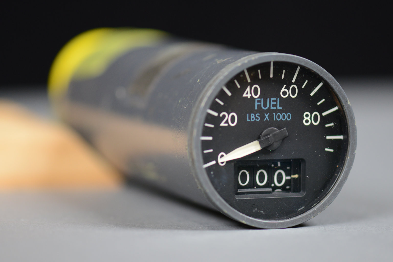
The front of several 747 fuel quantity indicators I have. This one maxes out at 95,000 lbs of fuel.
Pictured above is a 747 fuel quantity indicator. It has a dial and pointer that indicate the fuel quantity from 0 to 95,000 pounds. In addition, there’s a mechanical drum counter that indicates the fuel quantity with a resolution of 100 pounds from 0.0 to 95.0 thousands of pounds.
This gauge is most likely from a 747-200 where a third crewmember, the flight engineer, managed the fuel consumption of the aircraft. In later aircraft, like the 747-400, fuel management was computerized and the flight engineer’s position was eliminated in favor of a two crewmember flight deck. On these aircraft, the fuel quantity indicators are integrated into the glass cockpit displays of the pilot and first officer.
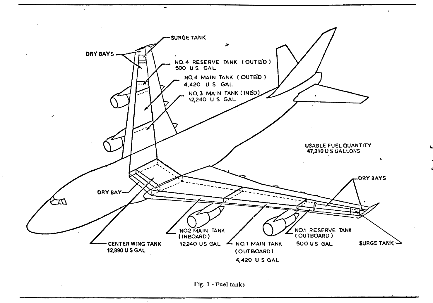
747 fuel tanks from The 747 Fuel System by E.D. Ayson, R.R. Dhanani, and G.A. Parker of The Boeing Company for the Society of Automotive Engineers, April 1970.
The illustration above is from an article on the 747 fuel system (PDF) from 1970. The 747-100 pictured has seven fuel tanks. Later versions of the aircraft added an optional 8th tank in the tail. Since jet fuel weighs about 6.7 to 6.8 pounds per gallon depending on formulation and temperature, this gauge is likely from the center tank (12,890 gallons or 87,000 pounds) or one of the two inboard wing tanks (12,240 gallons or 82,620 pounds). The gauge I later modify and control is likely from one of the two outboard wing tanks since it only goes to 35,000 pounds.
Barney Britton has some excellent flight deck photos from the first Boeing 747 aircraft on Tumbler. The last photo in this set shows the flight engineer’s console. The fuel management system is in the bottom center of the console with yellow knobs on either side of it. In that photo, you can see that the inboard and center tanks have gauges that go to 95,000 pounds, the outboard tank gauges only go to 35,000, and the reserve tanks only go to 3,500 pounds.
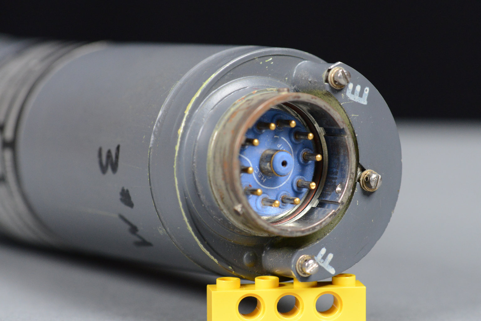
The rear view of a 747 fuel quantity indicator. The center contact is a shielded coaxial connection to the fuel level sensor. Behind the F/E panel are small potentiometers for calibrating the indicator.
The rear of the fuel quantity indicator is shown in the photo above. It has a cover marked with an F and an E and a large connector. Behind the cover are a few small potentiometers for calibrating the fuel quantity indicator. The connector has a center coaxial contact surrounded by 10 pin contacts. The center coaxial contact connects to the fuel level sensor which is called a tank unit as described in The 747 Fuel System:
Tank units, which sense fuel quantity, and compensator units in each tank provide input signals to the corresponding fuel quantity indicators. … The tank units are variable capacitors, their capacitance varying with the level of fuel in the tank. The compensator units … provide a correction for variation in dieletric constant with the fuel density.
A large metal band around the very end of the fuel quantity indicator seals the end plate and gauge internals inside the main body. The metal band is likely welded in place then covered with gobs of gray paint.
Internal Photos
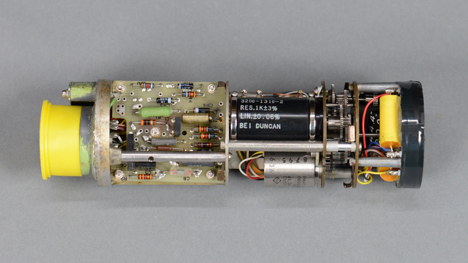
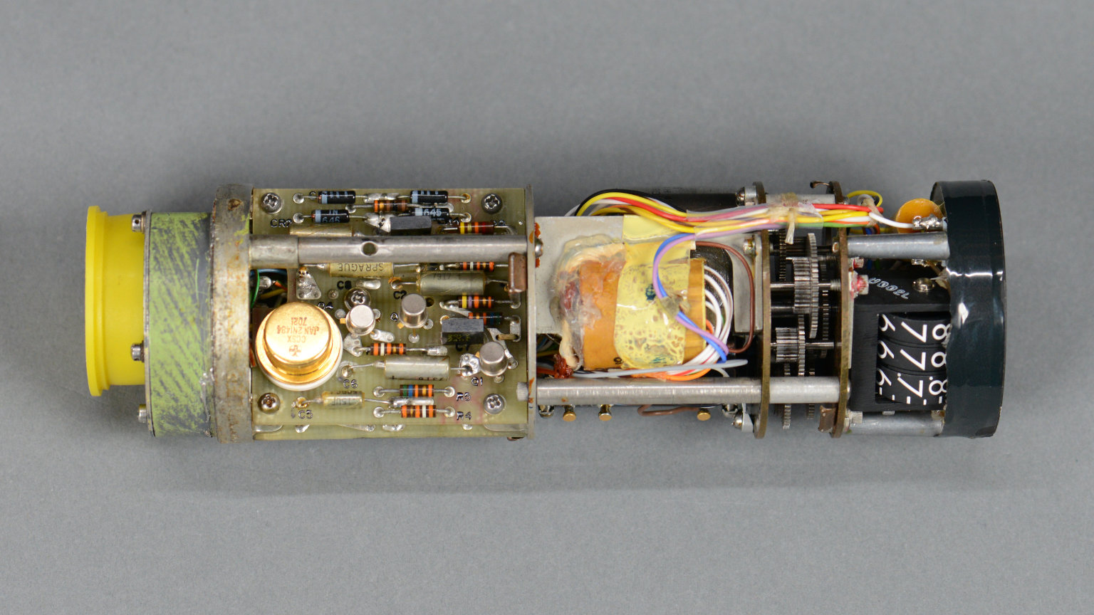
Internal photo of a 747 fuel quantity indicator. The large black cylinder is the feedback potentiometer for the control loop. The small cylinder below it is the AC servo motor that moves the pointer and counter.
One of the indicators I have came with the end seal already removed. These internal photos are from that indicator. In the photo above, 1 of 2 electronics boards is visible at the left end of the gauge. To the right of that is a large black cylinder. The black cylinder is the feedback potentiometer for the control loop that manages the pointer position and counter value.
Below that is a smaller, silver cylinder. The silver cylinder is the AC servo motor used to rotate the pointer and counter. To the right of those are a bunch of gears that couple the servo motor, feedback potentiometer, pointer, and counter together in various ratios. Finally 1 of 2 large yellow capacitors for the motor is visible.
The other side of the insides of the 747 fuel quantity indicator. A small transformer and the bottom of the mechanical drum counter are visible from this angle.
Flipping the indicator over as shown above reveals the second of the two circuit boards in the indicator. The power supply transformer and bottom of the mechanical drum counter are visible from this angle.
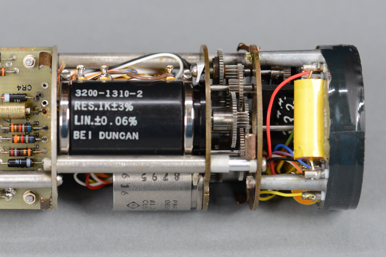
Closeup of the highly linear feedback potentiometer. 1 kΩ ±3% with a linearity of ±0.06%.
The photo above is a closeup of the feedback potentiometer. The resistance is 1 kΩ ±3%. The linearity spec is ±0.06% which likely places this part at the stratospheric end of expensive.
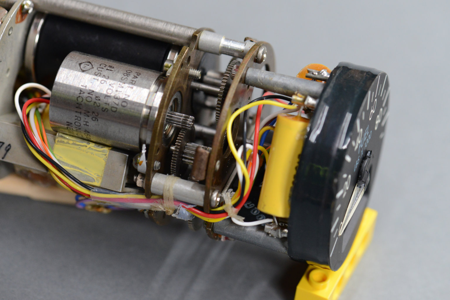
A closeup of the servo motor and 1 of 2 large capacitors in the indicator. The motor is rated for 26 VAC on both phases.
The photo above is a closeup the AC servo motor and some of the gears it turns. The AC servo motor has two windings. Both windings are rated for 26 VAC 400 Hz.
Mechanical Operation
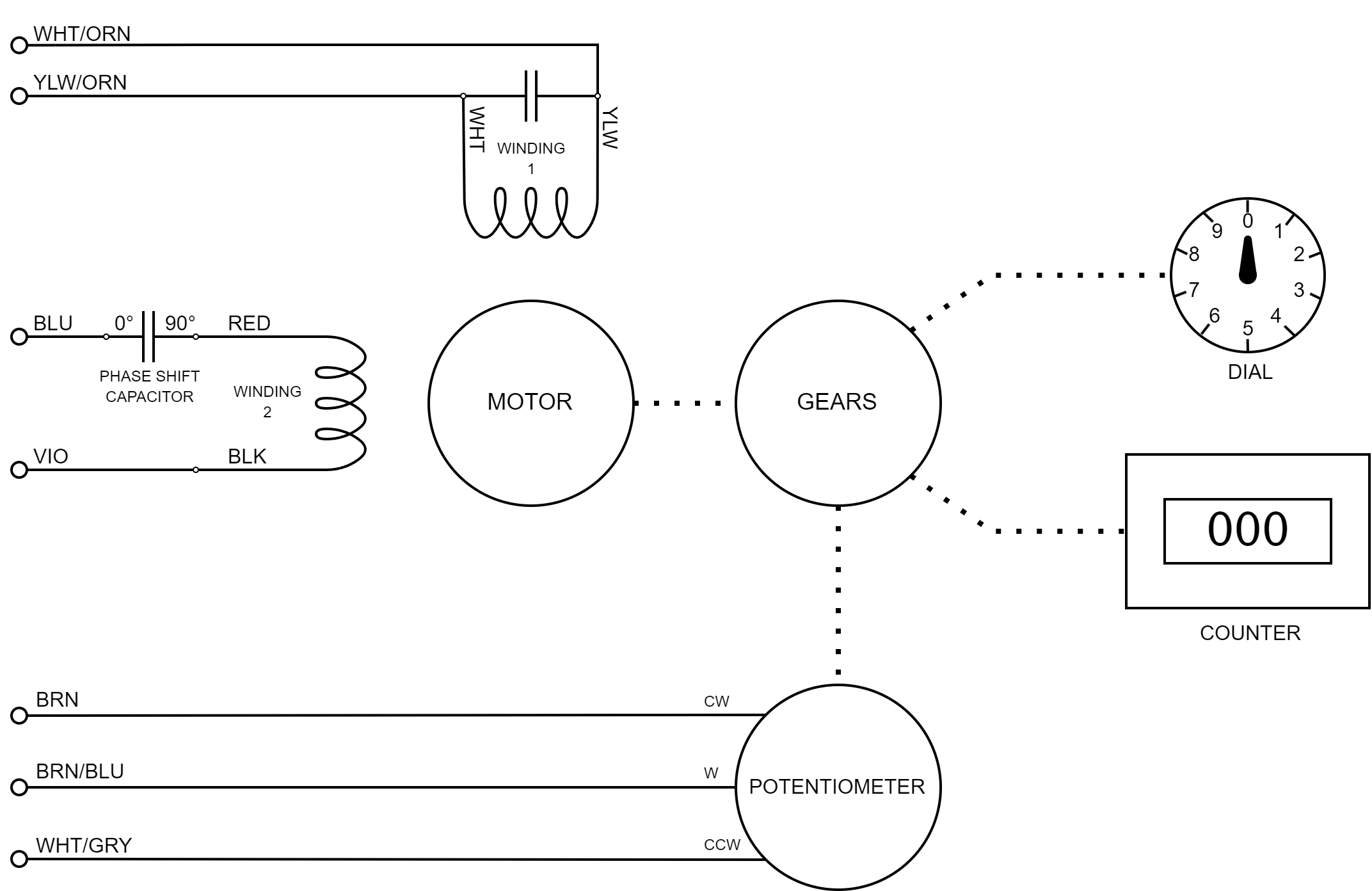
A reverse engineered block diagram of the electromechanical portions of the fuel quantity indicator.
After inspecting the indicator and identifying the various components, it was time to reverse engineer parts of the gauge to see if I could get it working again. The gauge is likely powered from 115 VAC 400 Hz and would require a variable capacitance to control it. Neither of which was something I wanted to try to implement. With some reservation, I decided the stock electronics would have to go and I focused my reverse engineering on the electromechanical parts of the indicator.
The diagram above documents my reverse engineering efforts. Looking at the diagram, a two-phase AC servo motor turns some gears. The gears turn the dial pointer, the drum counter, and the feedback potentiometer. The motor wires and potentiometer wires connect to the power supply transformer and circuit boards. The 90° phase shift required between the motor windings is provided by one of the two large yellow capacitors in the indicator. My plan is to disconnect the seven wires shown on the diagram from the stock electronics and connect them to my own electronics instead.
Hacking the Gauge
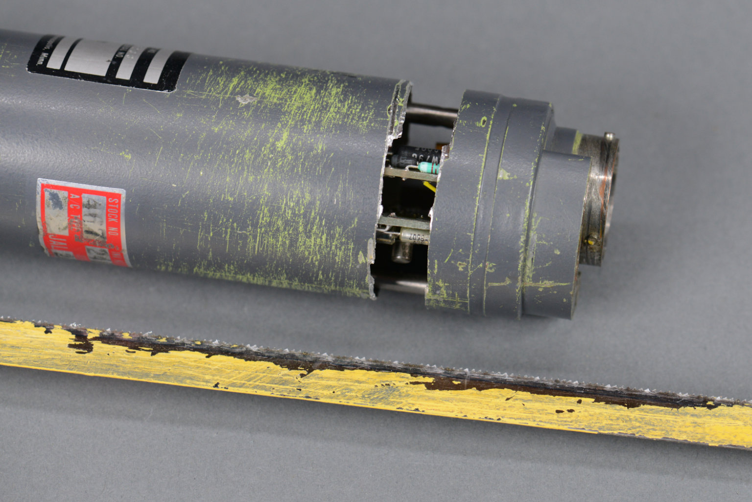
The first step in the hack was to hack open the fuel quantity indicator with a hack saw.
So far, we’ve been looking at a pair of indicators that go from 0 to 95,000 pounds. Both of these indicators were in too good of condition to hack up. I have a third indicator, however, that was in rougher condition. It is from one of the outboard tanks so it only goes from 0 to 35,000 pounds. I decided to make this indicator the subject of my hacks.
The first step in the hack was to get the indicator open. My weapon of choice was a hacksaw. The indicator body is aluminum so a hack saw cut it open fairly easily and quickly. I was careful not to nick the circuit boards or internal wiring. If I ever had to do this again, I’d probably attack the band at the end of the unit with a rotary tool and pair of pliers.
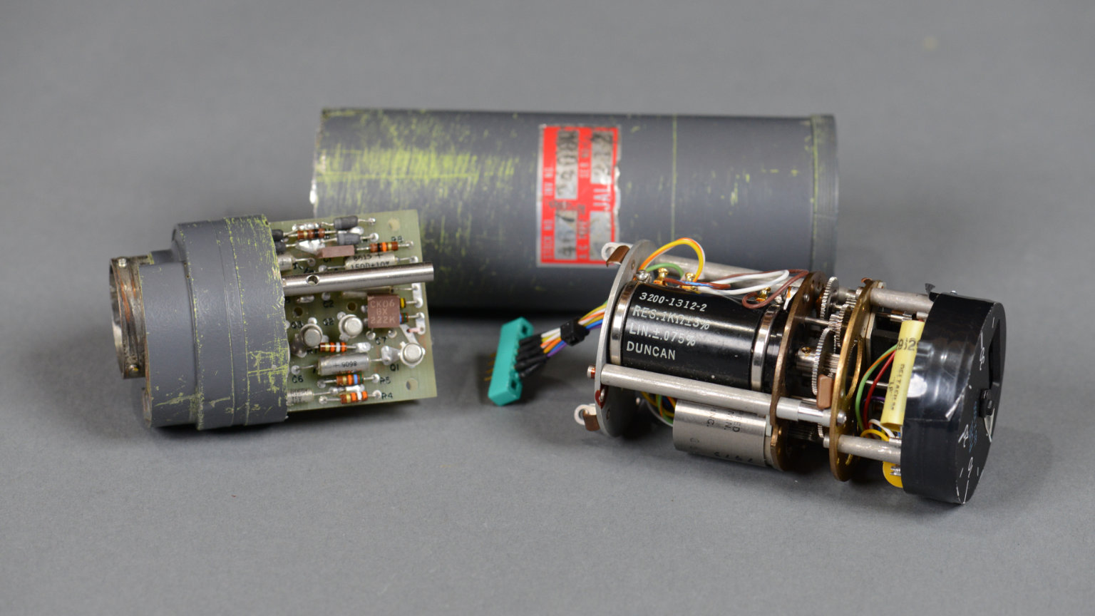
The cracked open and separated indicator. I added the green connector to the assembly to make connecting to my electronics easier.
I removed the indicator body from its shell, unscrewed the screws holding the circuit boards in place, and carefully disconnected the seven wires connected to the motor and potentiometer as well as the lamp power and chassis ground wire. These wires were all ridiculously short so I soldered them onto a connector then soldered longer wires onto a mating connector to give the wires more reach.
After carefully separating the electromechanical parts from the electronic parts, I soldered a connector to the motor, lighting, and feedback potentiometer wires.
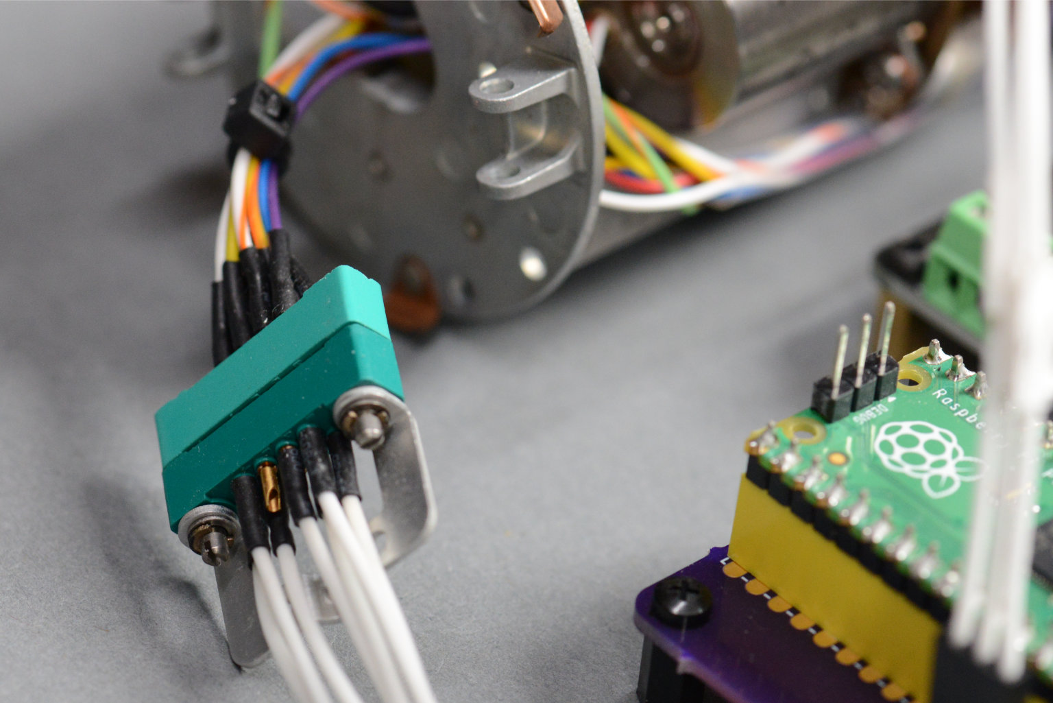
The photo above is a closeup of the connector I added to the indicator wiring and the mating connector that runs to my hardware.
| My Pin | Original Color | My Function |
|---|---|---|
| A | BLU | constant motor winding (+) |
| B | VIO | constant motor winding (-) |
| C | YLW-ORN | variable motor winding (+) |
| D | WHT-ORN | variable motor winding (-) |
| E | GRN-ORN | chassis / lighting ground |
| F | YLW-BRN | lighting (+) |
| H | BRN-BLU | POT WIPER |
| J | WHT-GRY | POT CCW (GND) |
| K | BRN | POT CW (+3.3V) |
The table above documents the wiring of the connector I added and each pin’s function.
The Controller
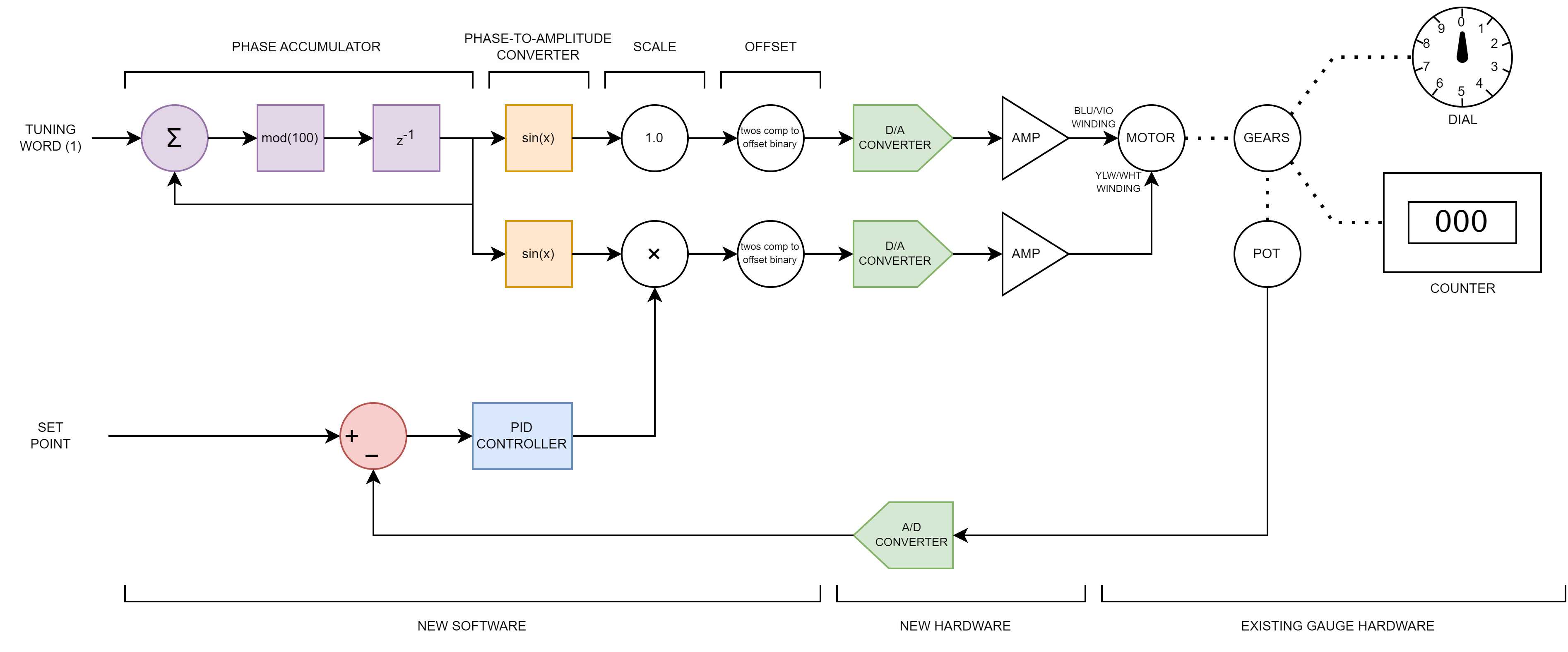
The block diagram of my replacement controller for the 747 fuel quantity indicator is shown above.
The block diagram for my controller for the indicator is shown above. This controller combines a two channel version of the AC power supply I used for my tachometer project and a PID controller. In this case, the AC power supply frequency is fixed at 400 Hz.
The first channel of the AC power supply has a fixed magnitude and drives the blue / violet winding of the AC servo motor. A large series capacitor on the blue / violet winding ensures the two motor windings are driven 90° out of phase as required by an AC induction motor.
The second channel of the AC power supply has its sign and magnitude scaled by the output of the PID controller and drives the yellow / white winding of the AC servo motor. This winding controls the speed and direction of the AC servo motor in response to the output of the PID controller. (For more details on AC servo motor operation, see the AC servo motor section of my altitude indicator project.)
The motor then drives the dial pointer, drum counter, and feedback potentiometer through a series of gears. The voltage across the potentiometer represents the current value of the dial and counter. The voltage is digitized using an analog-to-digital converter and used to compute the error between the desired pointer / counter value and the current pointer / counter value. The error is input to the PID controller to close the control loop.
The Hardware
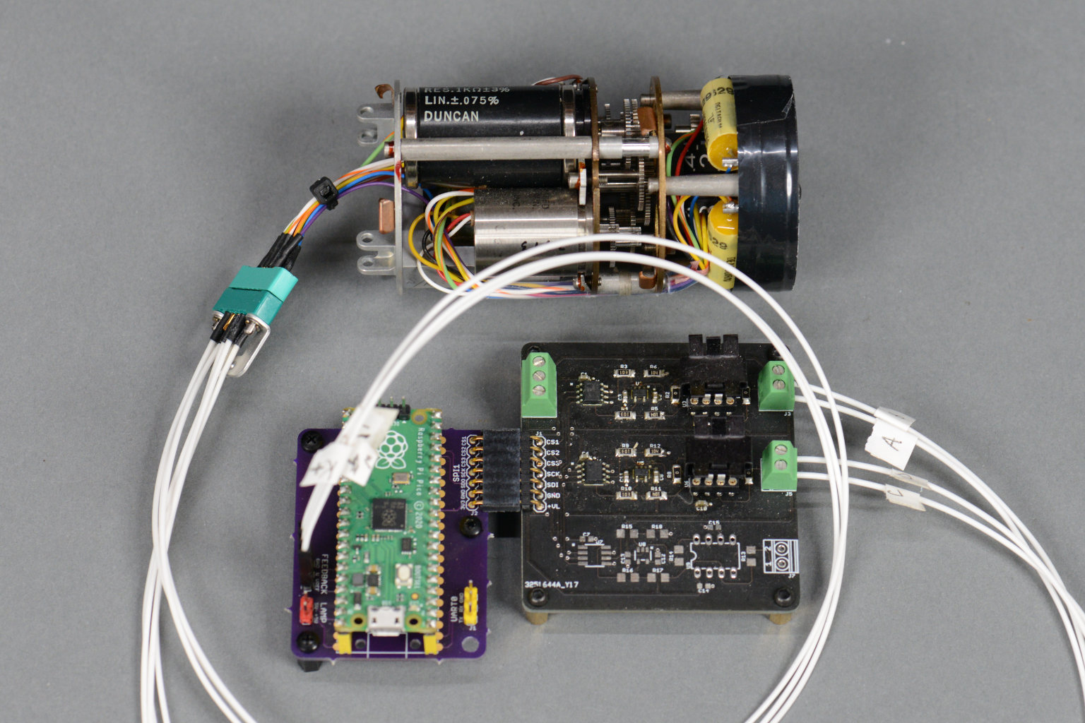
The hacked fuel quantity indicator and my controller hardware.
The hardware for this project is exactly the same as the hardware for the tachometer project except this project makes use of one of the Raspberry Pi Pico’s analog-to-digital converter channels and only requires 2 of the 3 DAC and amplifier channels to be stuffed. The feedback potentiometer is connected to the ADC channel using the 3-pin header on the Pico adapter board. The blue / violet motor winding is connected to the first DAC channel and the yellow / white motor winding is connected to the second DAC channel.
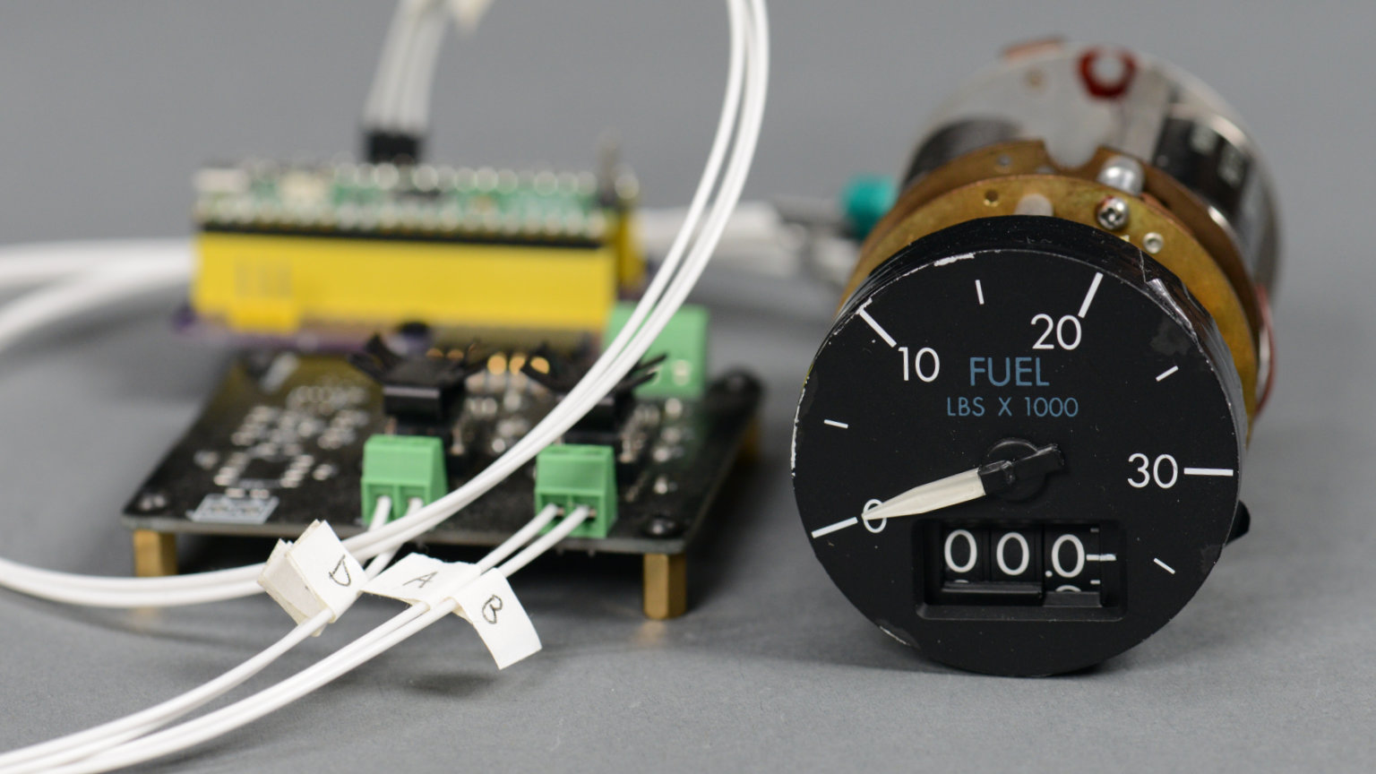
Another view of the hacked fuel quantity indicator and my controller hardware.
The photo above is another view of the hardware. This photo shows the face of the outboard wing tank fuel quantity indicator for the first time.
The Software
The software for this project consists of three main tasks:
- The first task is to prompt the user for the number of thousands of pounds to indicate on the dial and counter. This value is transformed into a 12-bit set point. This task runs as needed to receive an input from the user using a simple command line interface.
- The second task is to read the RP2040’s A/D converter to obtain the current position of the pointer and counter, calculate the error between the set point and the current position, and run the PID controller to calculate the next gain value that’s used to adjust the magnitude of the AC servo motor’s control winding voltage. This task runs at 100 Hz.
- The third and final task is to generate the two channels of sine waves to control the motor. This task runs at 40 kHz to output a sine wave that has been sampled at 100 discrete points. This results in 400 Hz sine wave outputs.
User Input Task
The code for the user input task is shown below:
// run get command state machine to get a line of input (non-blocking)
GetCommand ();

// once a line of input is received, process it
if (cmd_state == 2) {
    int index = 0;
    char *buffptr = strtok (cmd_buffer, ",");
    while (buffptr != NULL) {
        switch (index++) {
            case 0:
                target = pwl_interp (atof (buffptr));
                target = (target > 4095) ? 4095 : target;
                target = (target <    0) ?    0 : target;
                printf ("target = %d\n", target);
                break;
        }
        buffptr = strtok (NULL, ",");
    }
    cmd_state = 0;
}
This code sits in the main loop and runs the command interpreter state machine as often as it can. Once a return (0x0d) is encountered in the input stream, the command line is processed.
The first value entered on the command line is converted to a floating point number representing the number of tens of thousand of pounds to indicate on the indicator. For example, entering 10.3 would be interpreted as needing to position the pointer just clockwise of the 10 mark while moving the counter to indicate 10.3.
This value is converted to the expected analog-to-digital reading for this location on the dial and counter using a piecewise linear interpolation scheme and a sparsely populated table of known pounds to A/D readings. In the case of 10,300 pounds, the expected A/D reading would be 1338. This value, 1338, becomes the set point for the PID controller.
PID Controller Task
The PID controller task runs at 100 Hz. The code is shown below:
//----------------------------------------
// run pid loop
//----------------------------------------

// get lots of adc readings
sum = 0;
for (i = 0; i < 512; i++) {
    sum += adc_read ();
}
position = round (sum / 512.0);

// calculate error
error = target - position;

// calculate P term
pTerm = KP * error;

// calculate I term
sumError += error * Ts;
if (sumError > Imax*Ts) sumError = Imax*Ts;
if (sumError <= -Imax*Ts) sumError = -Imax*Ts;
iTerm = KI * sumError;

// calculate D term
deltaError = error - lastError;
lastError = error;
currentFilterEstimate = (alpha*previousFilterEstimate) + (1-alpha)*deltaError;
previousFilterEstimate = currentFilterEstimate;
dTerm = KD * currentFilterEstimate / Ts;

// add terms together
float newScale = pTerm + iTerm + dTerm;

// saturate result
if (newScale > 1.0) newScale = 1.0;
if (newScale < -1.0) newScale = -1.0;

// update speed and direction for core 1 ISR
critical_section_enter_blocking (&scale_critsec);
scale = newScale;
critical_section_exit (&scale_critsec);
Every 10 ms, this code gets an A/D reading, calculates the error between the set point and the A/D reading, calculates and sums the P, I, and D terms of the controller, saturates the result, then safely writes the saturated result to the sine wave generator task using a critical section.
The A/D reading actually consists of 512 A/D readings taken in rapid succession and averaged together. This removes noise in the potentiometer and A/D converter that can wreak havoc with the derivative term of the PID controller. These effects will be discussed in the next section of this post.
The error, error, is simply the difference between the set point, target, and the actual position, position. The next few lines calculate the P, I, and D terms of the PID controller. These calculations rely heavily on a bunch of constants defined earlier in the file. The values of these constants are the result of tuning the PID controller and will vary from system to system. Finally, the sum of the P, I, and D terms is saturated to a value between -1.0 and +1.0 and passed to the interrupt service routine that generates the sine waves.
Sine Wave Generator Task
The sine wave generator tasks runs at 40 kHz and generates a pair of 400 Hz sine waves using a table of 100 samples of a single complete sine wave:
bool repeating_timer_callback_40kHz (struct repeating_timer *t)
{
    uint16_t a;

    a = 0xB000 | ((uint16_t)dac0B << 4);
    gpio_put (SPI_CS0n_PIN, 0);
    spi_write16_blocking (SPI_IF, &a, 1);
    gpio_put (SPI_CS0n_PIN, 1);

    a = 0xB000 | ((uint16_t)dac1B << 4);
    gpio_put (SPI_CS1n_PIN, 0);
    spi_write16_blocking (SPI_IF, &a, 1);
    gpio_put (SPI_CS1n_PIN, 1);

    if (++sin_phase >= 100) {
        sin_phase = 0;
    }

    critical_section_enter_blocking (&scale_critsec);
    dac0B = 128+sine[sin_phase];
    dac1B = 128+scale*sine[sin_phase];
    critical_section_exit (&scale_critsec);

    return true;
}
This code outputs the current value of the sine waves to the DACs using one of the Pico’s two SPI peripherals. It then updates the sine waves’ phase modulo 100 since the sine wave consists of 100 points. Once the phase is updated, it calculates the next value of the fixed-magnitude sine wave used to power the AC servo motor and the next value of variable-magnitude sine wave used to control the AC servo motor. The calculations are done inside a critical section so that the PID controller cannot write a new value of scale while the interrupt service routine is using it.
Putting it All Together
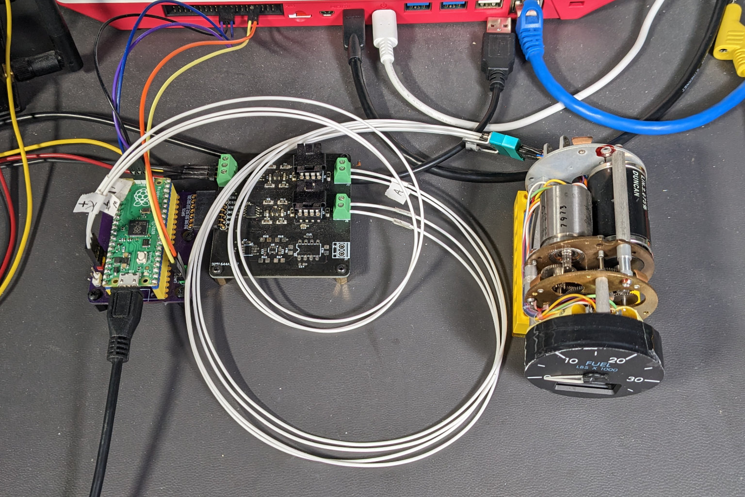
The complete test setup ready to go on the bench.
In the photo above, the Raspberry Pi Pico, adapter board, analog op amp & buffer board, and fuel quantity indicator are connected together. The red, yellow, and black wires go to a bench supply set for ±12 V with the current limit set at 150 mA. The yellow and orange wires connect the Pico’s serial port to a Raspberry Pi 400’s serial port. The purple, blue, and black wires connect the Pico’s SWD connector to the same Rasppberry Pi for programming and debugging. A micro USB cable supplies +5V power to the Pico.
Results
A video of my hardware and software controlling the pointer and counter on a 747 fuel quantity indicator.
With some fine tuning, the project worked! Two issues were encountered while building the project. These issues are documented below.
Derivative Issues
The derivative term of a PID controller is extremely sensitive to noise in the A/D converter readings. When I used only a single A/D reading per 100 Hz PID update cycle, the derivative term would cause the control value calculated in the PID loop to rapidly jump back and forth between -1.0 and 1.0 even though the pointer was very near or at the set point.
This resulted in high current consumption and the AC servo motor rapidly moving back and forth and changing direction without really moving the pointer or counter much. Even though the pointer and counter looked like they weren’t moving, this was causing wear and tear on the AC servo motor and drive gears which were moving.
Averaging 512 samples together as shown in the code above eliminated the noise and the issues with the derivative term of the PID controller. The AC servo motor now all but stops moving when the set point is reached.
Issues Around 22,500 Pounds
The second issue could not be solved. The potentiometer has a noisy or dead spot around 22,500 pounds. This results in the pointer and counter being a bit off from the set point when the set point is in the neighborhood of 22,500 pounds. The problem is worse when approaching this region from one direction than the other. Although I believe the aircraft this indicator came from was dismantled for parts, it’s possible this indicator was removed for this issue before the final decommissioning of the aircraft.
Conclusion
I would have preferred to operate the gauge intact and without permanent modifications but given the high AC supply voltage, the variable capacitor sensor, and the scarcity of the gauge’s mating mixed-contact connector, I did not deem this feasible with the parts and equipment I had accessible. Instead, I hacked the gauge to replace the normal electronics with my electronics. In a future revision of this project, I’d like to miniaturize my electronics so that they’d fit in the existing gauge enclosure.
Downloads
The board design files and software for this project are available in the 747 Fuel Gauge directory of my avionics repository on Github.
References
Boeing Aircraft Fuel Management
Boeing 747 RA001 Flight Deck Photos
How Does the Derivative Term Affect PID Controller Performance?