
The only way to make CAPS LOCK even more annoying was to make it audible! Now never type a password in all upper case, join 500 lines together in vi, or turn a harmless forum post into an ANGRY SCREED without warning again! This project uses a PIC16F1459 to monitor the USB output report containing the CAPS LOCK status from the connected PC. When CAPS LOCK is enabled, the PIC turns on an annoying warning buzzer. Read on to build your own.
Motivation
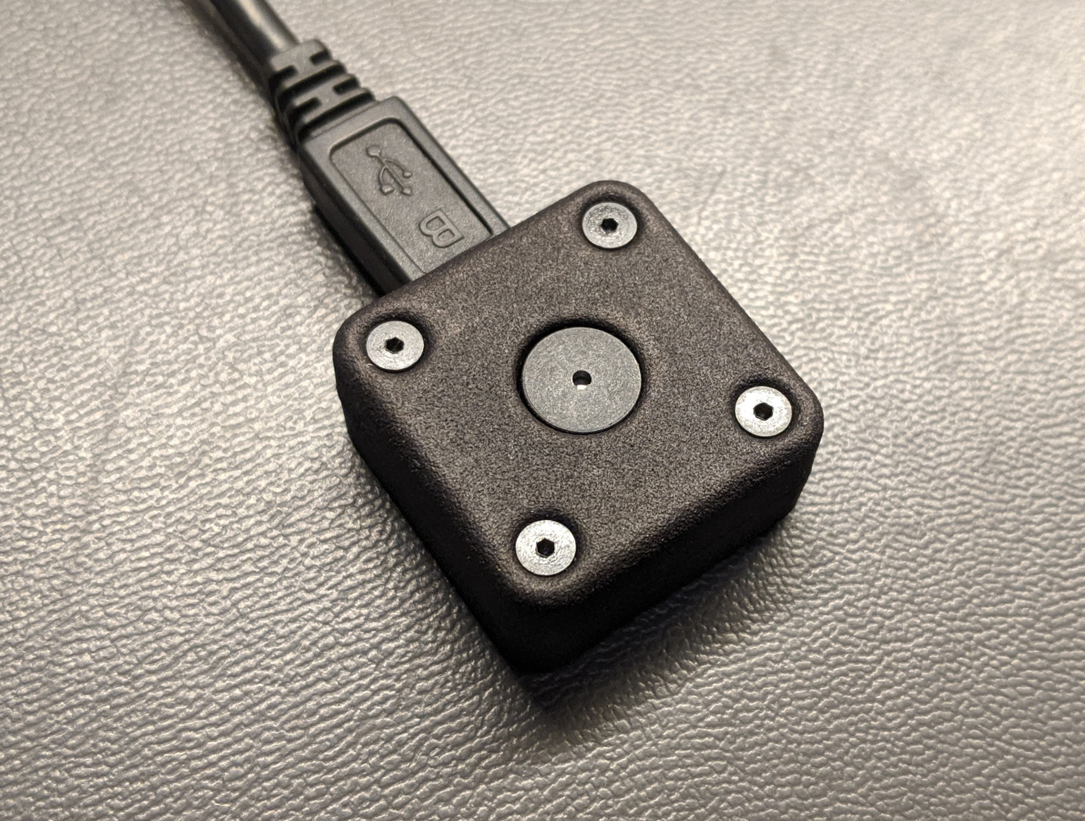
The completed annoying caps lock warning buzzer.
The CAPS LOCK key is the most annoying key on the keyboard. It’s always getting in the way. Ever enter a password with CAPS LOCK enabled? Enough times to get locked out of your account? Yeah, me too.
The only way to make CAPS LOCK even more annoying was to make it loud! As a side effect, you’ll always know when CAPS LOCK is enabled so entering the wrong password, joining lines when you’re just trying to scroll down in vi, or answering an entire email in ANGRY SCREED format should be history.
Derived from the One Key USB Keyboard
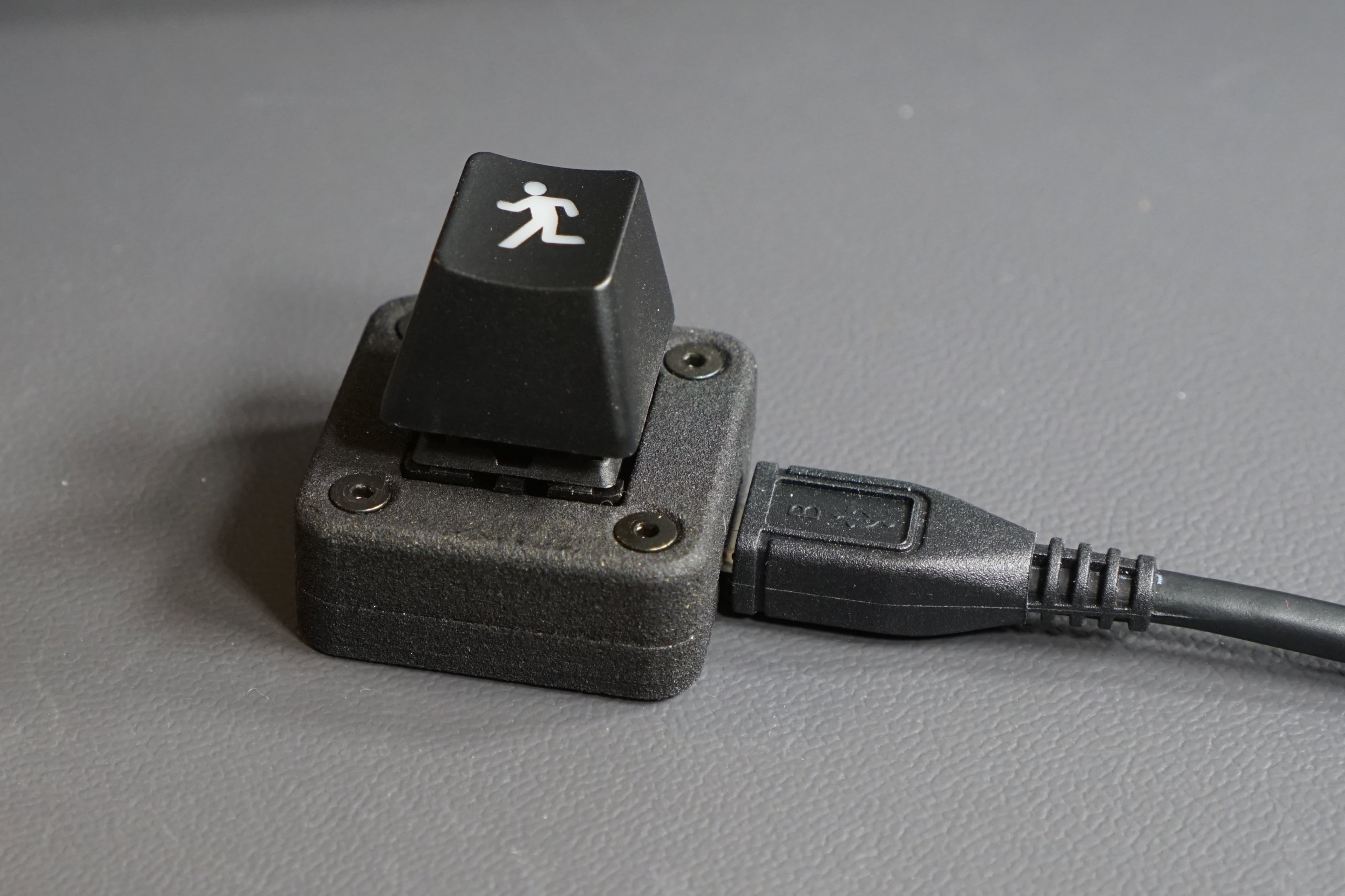
The single ESC key USB keyboard.
This project is almost identical to my one key USB keyboard project. The key switch and LED have been replaced by a transistor and a buzzer. The enclosure has a round hole instead of a square hole. The software previously turned on an LED when CAPS LOCK was set. Now it uses a different pin to enable the buzzer instead. A few small changes yield an entirely different result. The selecting parts section below is repeated verbatim from that design. Skip forward to the schematic section if you’ve already read it.
Selecting Parts
Picking a USB Microcontroller
I chose a PIC16F1459 in an SSOP-20 package for the microcontroller. The PIC16F145x family provides a minimal parts count solution to implementing the USB 2.0 standard. No external oscillator is required because this micro has an internal 48MHz oscillator and uses active clock tuning to fine-tune the internal oscillator frequency to the recovered clock from the USB host. This micro, a USB connector, and three capacitors are all that are needed to implement a fully-functional USB 2.0 device.
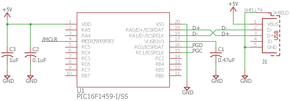
Minimal PIC16F1459 schematic for USB 2.0 operation.
Once I selected the microcontroller, I needed to pick a package for the microcontroller. The PIC16F1459 is available in DIP, SOIC, SSOP, and QFN packages. I chose the SSOP-20 package. The two larger packages were too big to fit in the allocated board space and the QFN package, though smaller, would be considerably more difficult to hand solder.
The USB Connector
Next up was to find a suitable USB Micro-B connector. Since the entire board was to be hand soldered, I wanted a connector with locating pins to position the connector on the board while I soldered it and with enough room between the connector housing and the five signals pins that I could easily see what I was doing with a microscope. I ordered a bunch of USB Micro-B connectors, examined each of them, and finally found a Wurth Electronics connector that met my needs.
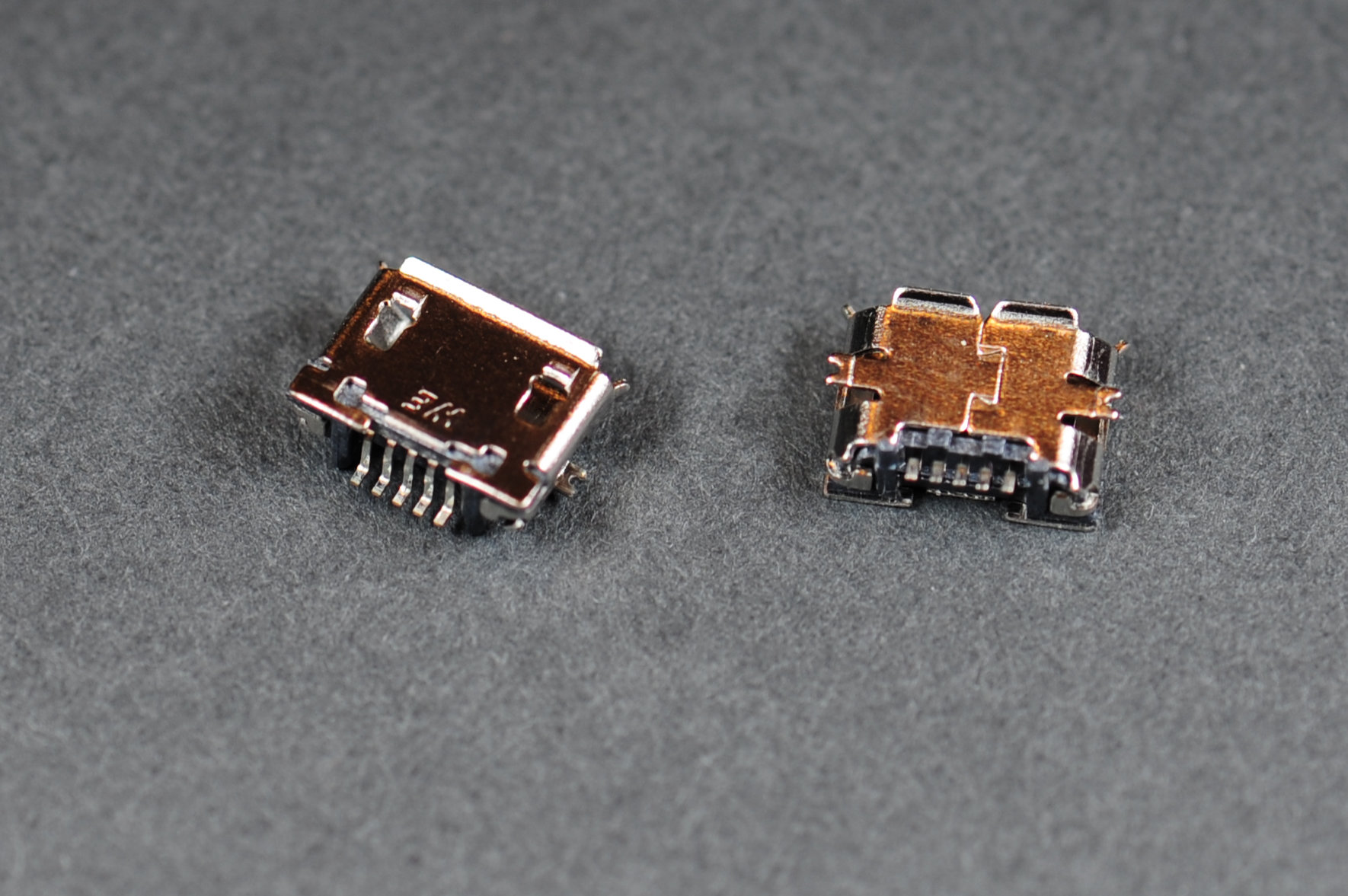
Wurth Electronics USB Micro-B Receptacle part number 629105136821. It has little black plastic posts to keep the connector centered while soldering and plenty of room between the shell and pins for the soldering iron, flux, solder, and inevitably, wick.
Schematic
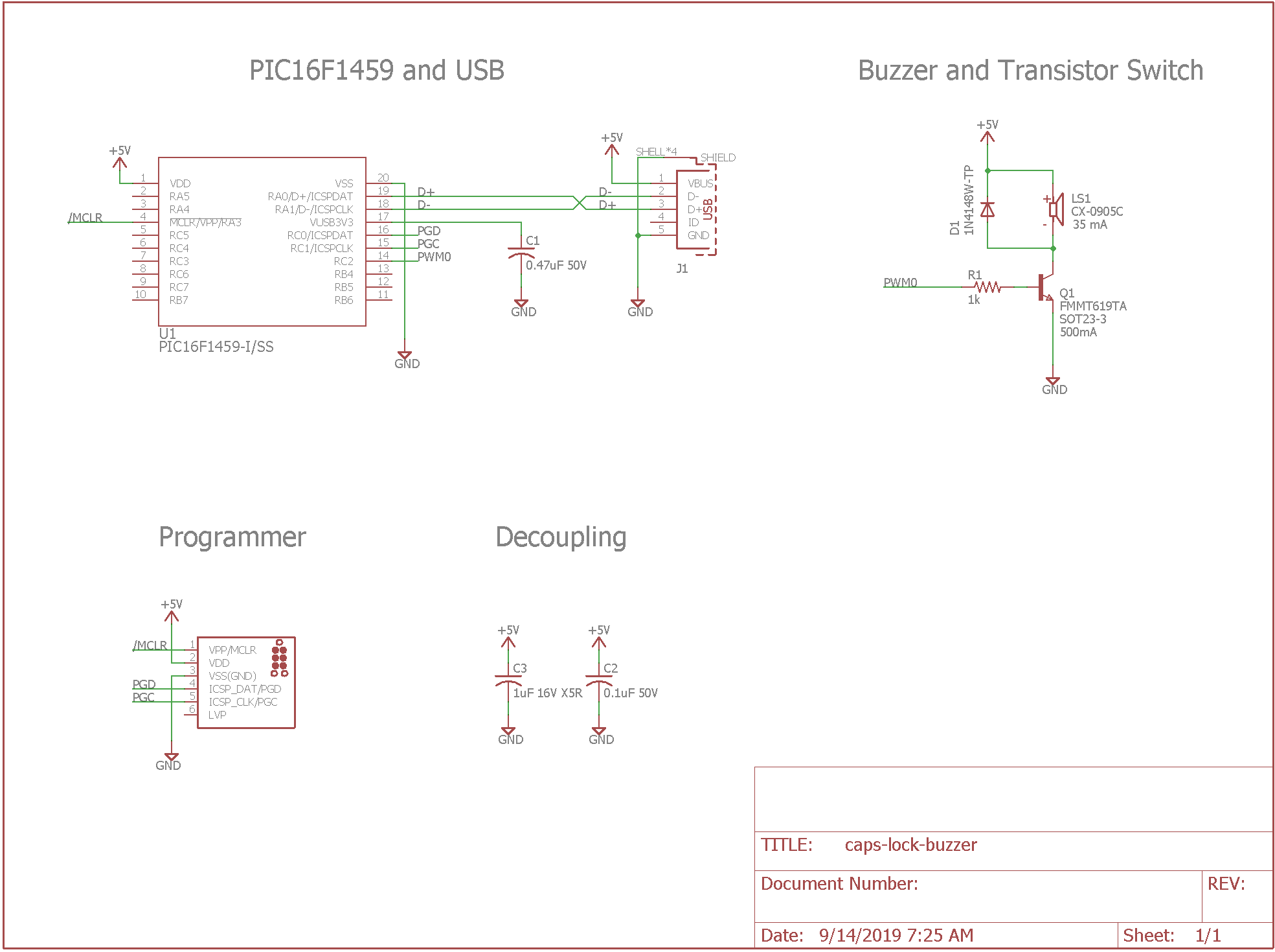
Schematic of the annoying caps lock warning buzzer.
Pictured above is the complete schematic for the caps lock buzzer. Let’s take a closer look at the buzzer, the transistor switch, and programming the PIC16F1459.
The Buzzer
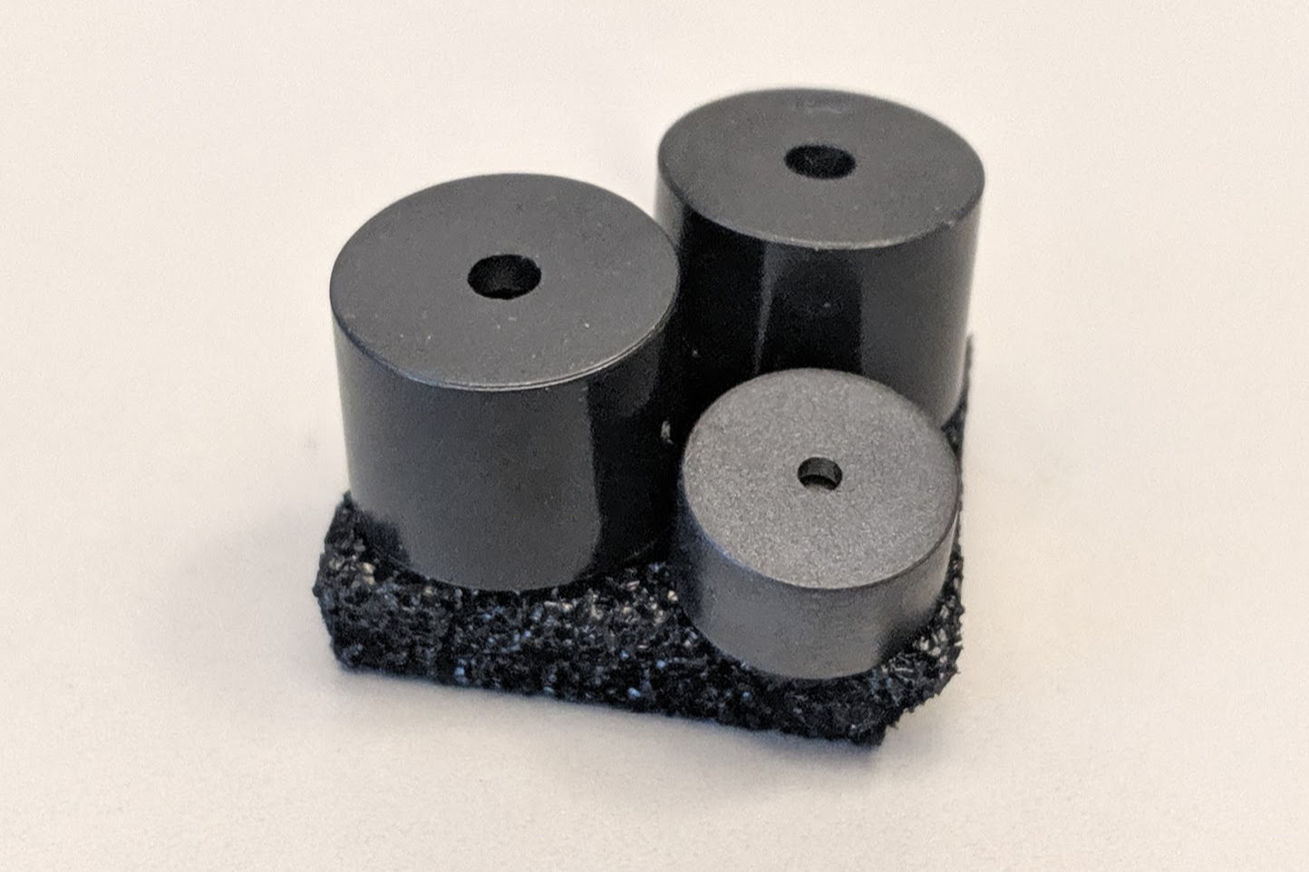
Buzzer candidates. I went with the smallest of the three.
The buzzer needed to run from 5V since that is the USB bus voltage. The current consumption needed to be less than 1 A to prevent overloading the USB bus. I selected a through-hole buzzer to make aligning the buzzer with the board and consequently the hole in the 3D printed enclosure simpler. The final criteria was to select a buzzer that fit in the existing one-key keyboard enclosure without protruding too much. I found a buzzer that ran from 5V, consumed 35 mA, and only protruded out of the existing enclosure design by 0.42 mm. The frequency is 2.7 kHz with an SPL of 80 dBA.
Designing the Transistor Switch
The transistor switch circuit is a pretty basic transistor switch circuit. When the PIC drives the PWM0 signal, current flows from the base through the emitter of the transistor. This current turns on the transistor and a current conducts from the positive supply rail, through the buzzer, and from the collector to the emitter of the transistor.
R1 is selected to drive the transistor into the saturation region and to minimize the heat dissipation in the transistor. A 1k resistor usually works well but let’s calculate the resulting current with a 1k resistor to double check. To calculate the minimum base-emitter current, we need to know the worst-case output voltage at the output of the PIC and the worst-case base-emitter saturation voltage of the transistor.
From the data sheet, the V(OH) of the PIC is V(DD)-0.7 volts and the V(BE)(SAT) of the transistor is 1.0 V. The minimum base-emitter current will be (5 – 0.7 – 1.0 V) / (1 k) = 3.3 mA. The current consumption of the selected buzzer is 35 mA and the h(fe) of the transistor is 200. The base current required to drive the transistor into the saturation region is 35 mA / 200 = 0.175 mA.
The transistor will definitely be operating in the saturation region when the PIC turns on the PWM0 output signal. We could use a higher resistor if we want to further minimize the heat dissipation of the transistor but 3.5 mA is much less than the maximum base-emitter current of the transistor and I have a lot of 0805 1k resistors in my parts box.
Diode D1 is present to protect the transistor from the flyback voltage generated by the inductive load of the buzzer when the transistor is switched off. The voltage that is created at the collector of the transistor will be safely sunk to the positive supply rail rather than building up to a level that could potentially destroy the transistor.
Programming the PIC16F1459
The old way of programming.
In previous designs, I’ve used a row of plated holes designed to make with a six-position, single-row, square-post, 0.1″ pitch header to connect to the PIC programmer and debugger (shown above). This works well but takes up a lot of area on both sides of the board.

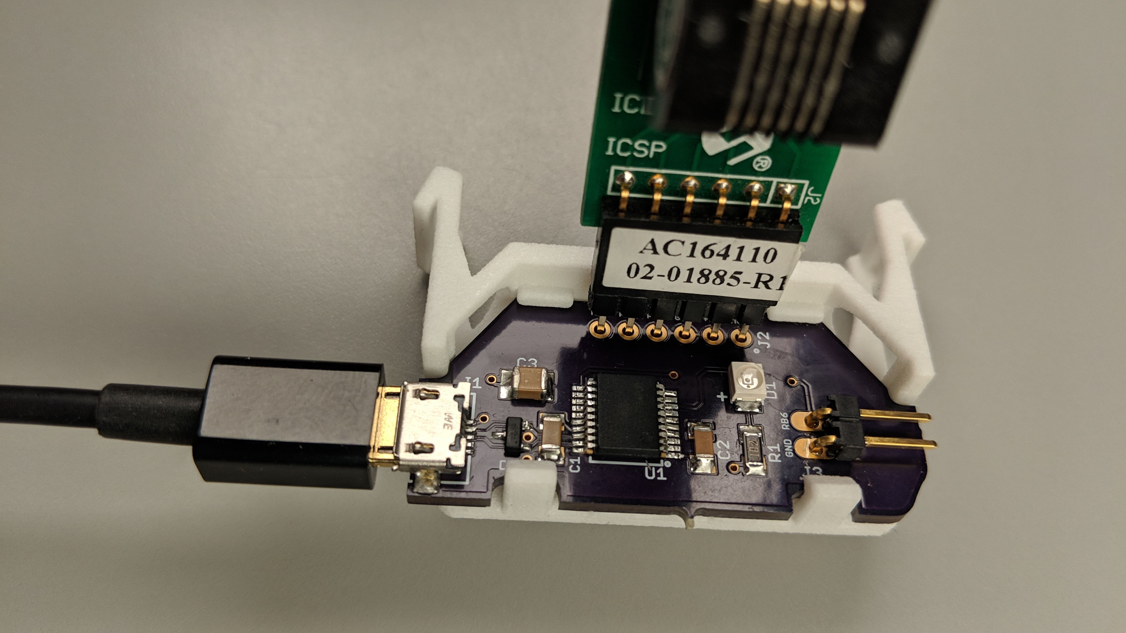
The new way: a Tag-Connect programming cable connected to the programming pins on the circuit board.
For this design, I’m using a TAG-Connect cable to connect the programmer/debugger to the board (shown above). This uses roughly half the area of the 0.1″ header and only requires holes for three small alignment pins.
Board
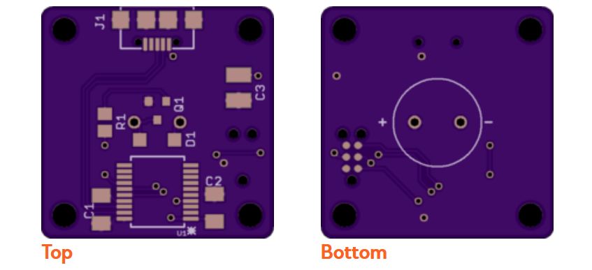
A rendering of the boards from OSHPark.com.
Shown above is a rendering of the completed board design. The board outline is identical to the board outline of the one-key keyboard board outline. The layout is very similar as well. Note the footprint for the Tag-Connect programming cable to the left of the buzzer on the bottom of the board.
Software
USB Output Reports and the CAPS LOCK State
The CAPS LOCK state of a keyboard attached to a PC is maintained by the PC; not the keyboard. If you attach five keyboards to a PC and hit the CAPS LOCK key on one keyboard, the CAPS LOCK light on all five attached keyboards will illuminate. You can then hit the CAPS LOCK key on a different keyboard and all the CAPS LOCK lights will turn off.
This is implemented by the connected PC sending a periodic USB output report to all the attached keyboards. Inside this USB output report is a bit indicating the current state of the CAPS LOCK, NUM LOCK, and SCROLL LOCK keys. Attached keyboards examine these bits when the USB output report is received and turn their lights on and off according to these bits.
The annoying caps lock buzzer looks like a keyboard to the host PC except it doesn’t have any keys. The host sends the periodic USB output reports to our “keyboard” and when the USB output report is received, our “keyboard” turns the buzzer on or off to match the state of the CAPS LOCK bit in the USB output report.
Writing the Software
The software for this design is based on the Microchip Library for Applications (MLA) USB HID demo for low-pin count PIC micrcontrollers. In the unmodified version of the software, the software turns an LED on or off based on the USB output reports described in the previous section.
To make the annoying caps lock warning buzzer, I only had to change the pin used to turn the LED on or off from the default in the software to pin RC2, disable sending any pressed keys to the host PC, and recompile.
Initial Bring Up
One milliamp with an unprogrammed microcontroller and the buzzer turned off is about right. It’s now safe to connect the buzzer to the PC without worrying about damaging the PC.
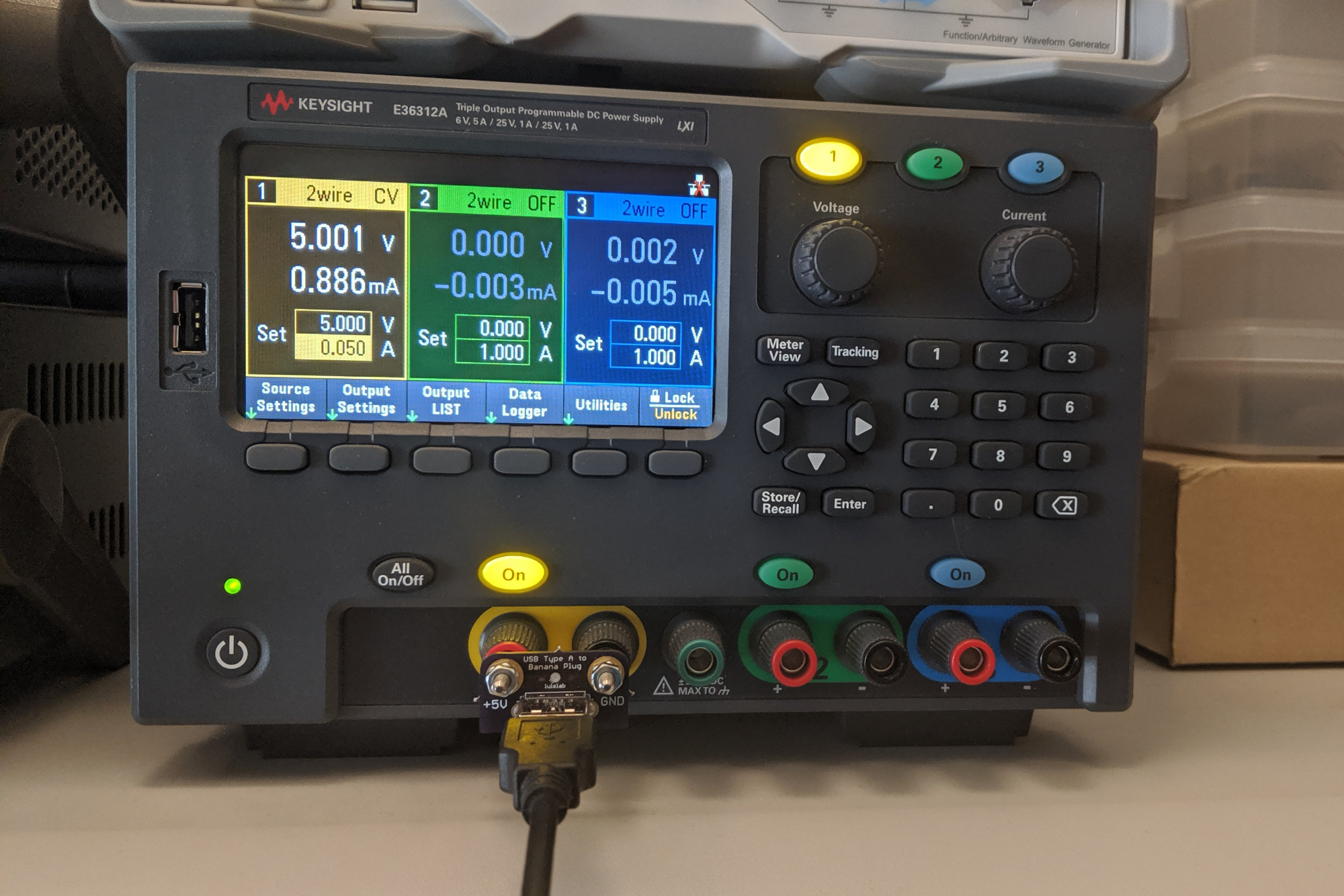
For the initial bring up and programming, I used a Keysight 36312A DC power supply and a double-banana plug to USB Type A adapter from Luislab (shown above). I set the DC power supply to 5 Volts and set the current limit to 50 mA. This way if I accidentally shorted power to ground while soldering or there was a defect in the board, the power supply would go into current limit mode at a safe limit rather than causing damage to the board or my PC.
The USB Type A ports on a PC are required by the USB spec to have a self-resetting PTC fuse on them to protect the PC against damage if the connected USB device or cable has a short or draws too much current. The trip point for the thermal fuse is 1 A. In theory, I could plug the board into my PC for the initial bring up but the PC’s USB port is really not designed to limit current. It’s a safer option for my design and my PC to use a current-limited DC power supply for the initial bring up than to use one of my PC’s USB ports or a phone charger.
Measurements
Verifying the Transistor Switch is Operating in the Saturation Region
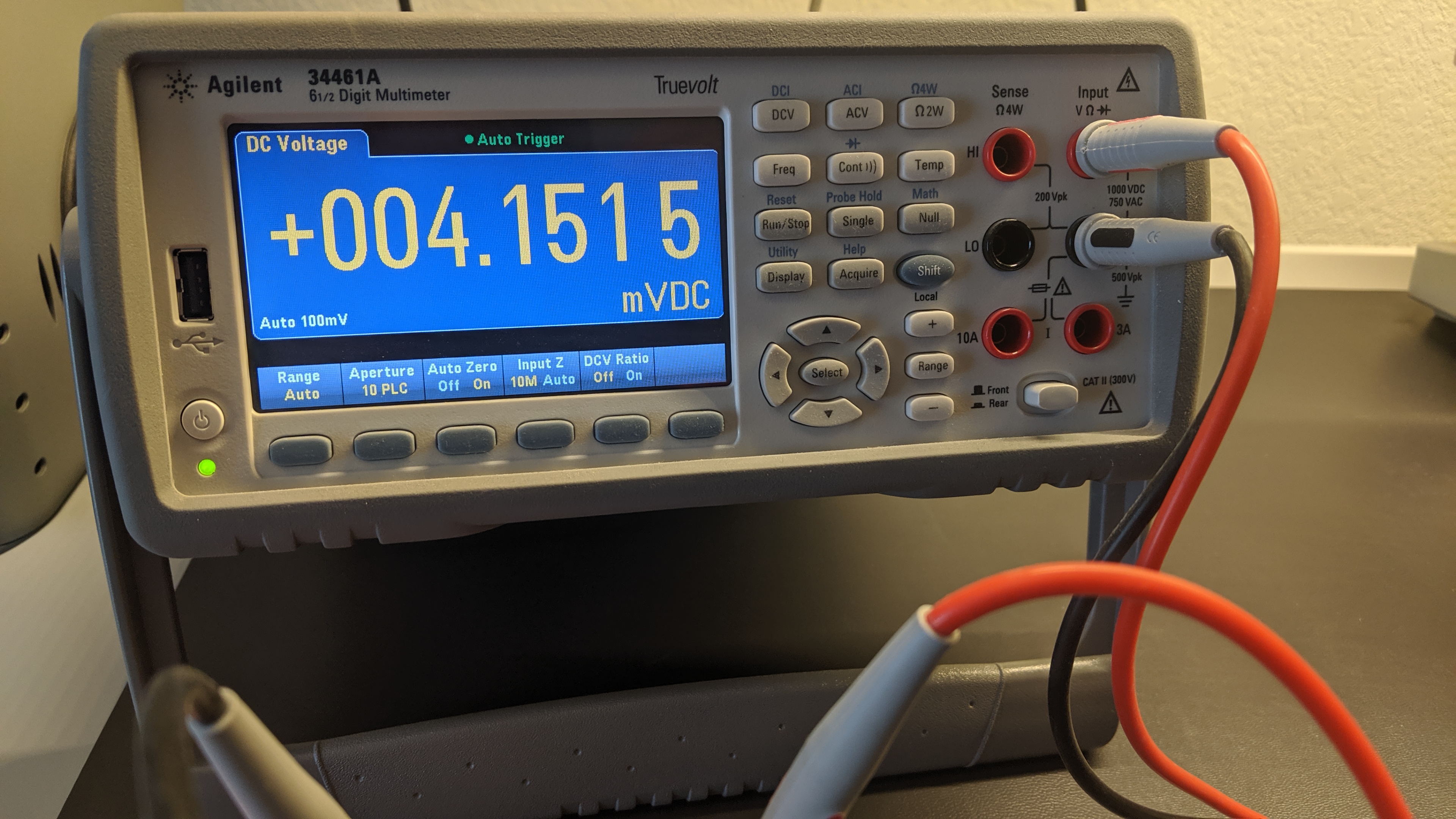
Using my 34461A to measure V(CE).
After bringing up the board and programming the microcontroller, I wanted to verify the transistor in the transistor switch was operating its saturation region. To do this, I used a Keysight 34461A DMM to measure the voltage between the collector and emitter of the transistor while the buzzer was on. The measurement was 4.1515 mV. The transistor is clearly operating in its saturation region. If it had not been, I would have needed to lower the value of R1 to increase the base-emitter current.
Current Measurements
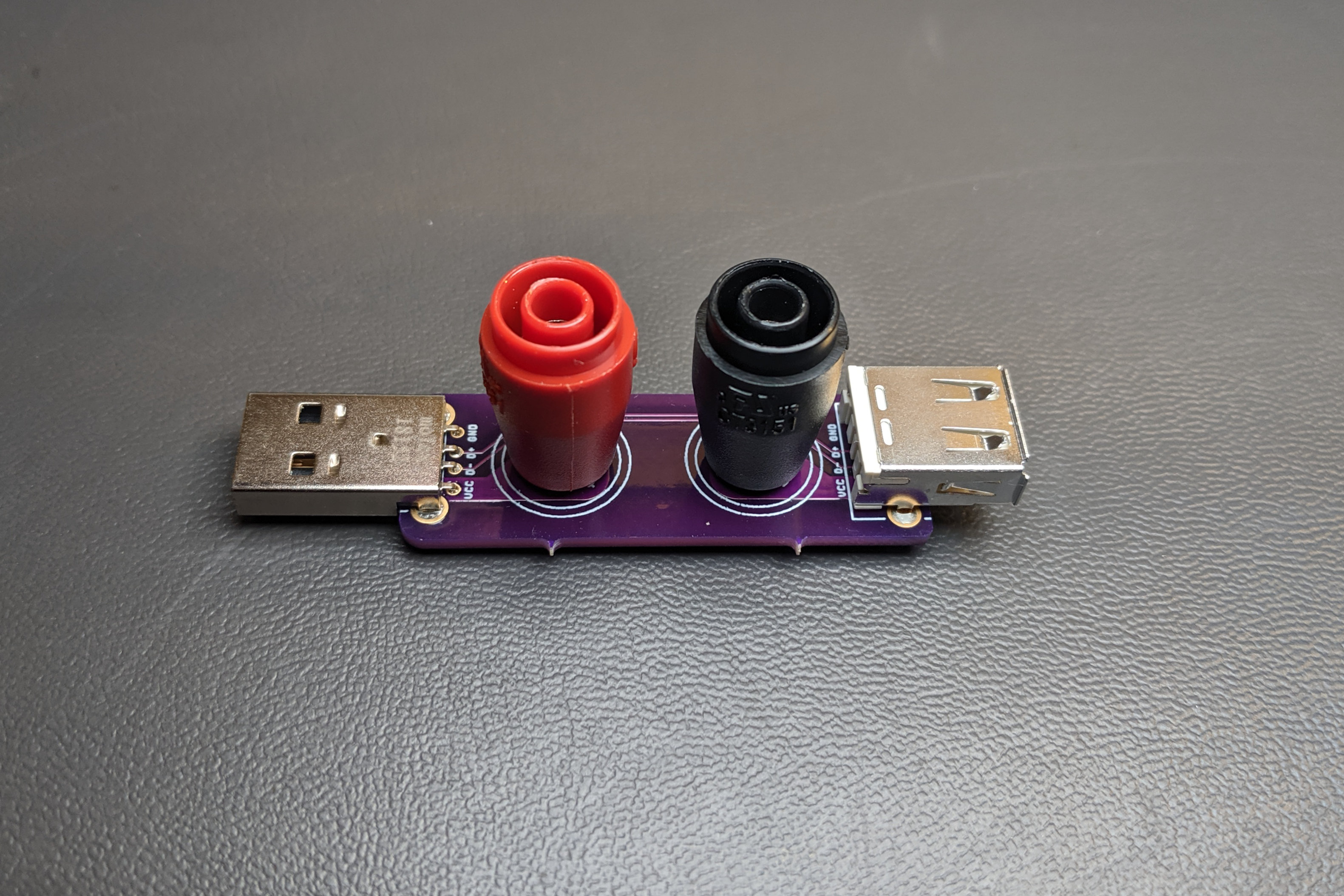
USB current probe board.
To measure the current I built a USB current probe board. This board connects the USB D+, D-, and ground lines directly from input to output. The +5V USB power from the PC is brought out to a red banana jack and the +5 power to the target is brought out to a black banana jack. A DMM in current measuring mode can then be connected to the two binding posts and used to measure the current consumption of the USB device.
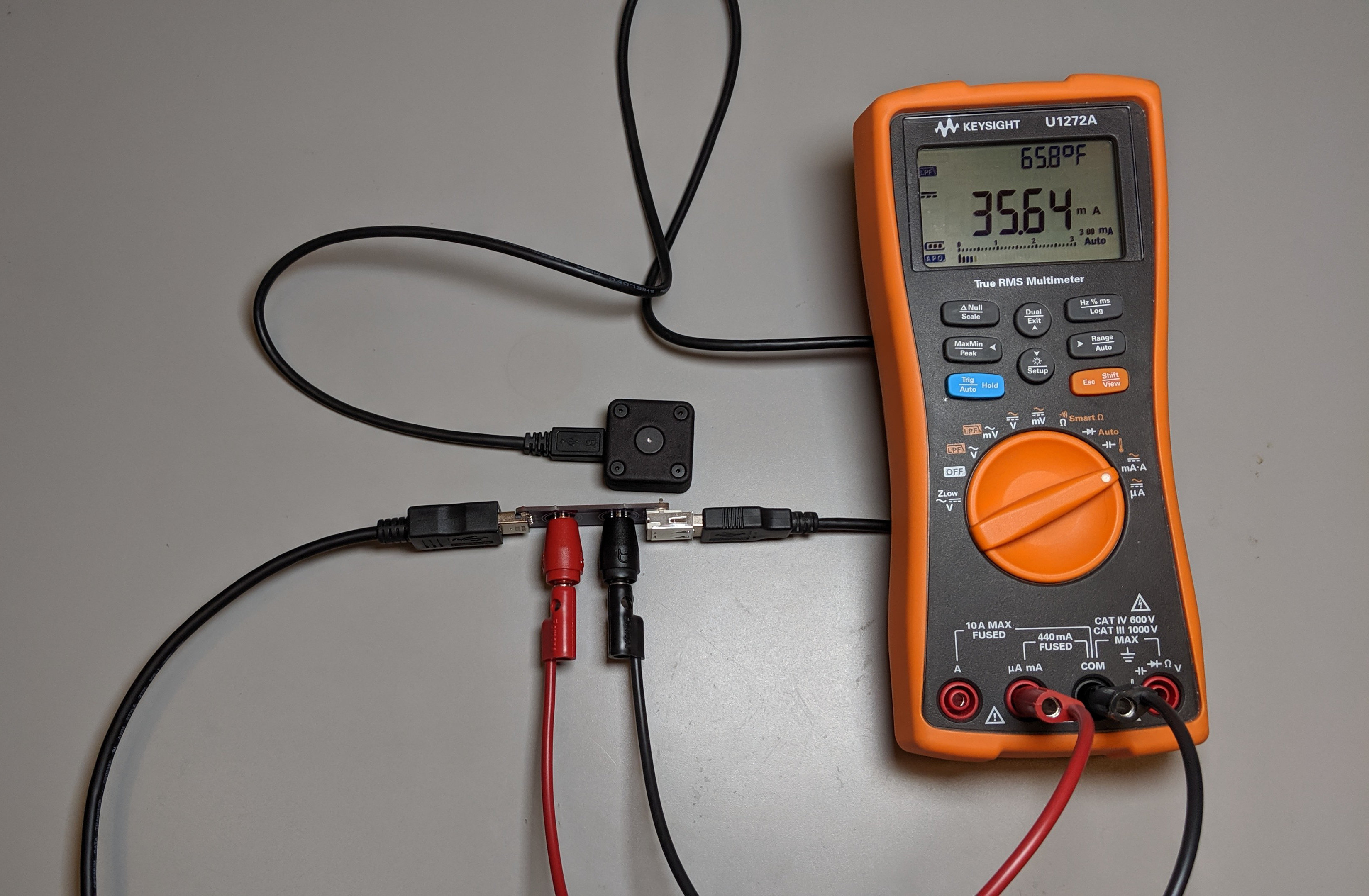
Current measurement with the buzzer on.
To measure the current, I connected the USB Type A plug on the current probe board to my PC using a USB extension. I connected the annoying CAPS LOCK warning buzzer to the the USB Type A receptacle on the current probe board using a USB A to Micro B cable. I then connected the banana jacks on the current probe board to the the low range current measurement inputs on my Keysight U1272A DMM.
With the buzzer off and the annoying CAPS LOCK warning buzzer enumerated on the USB bus on my PC, I measured a current of 8.062 mA. I then engaged CAPS LOCK on my PC and measured the current with the buzzer on. With the buzzer on, I measured a current of 35.64 mA. Both of these numbers are well below the maximum a USB Type A port on a PC can supply and reasonably match the expected values in the data sheets for the PIC16F1459 microcontroller and the buzzer.
(Disclaimer: I work for Keysight. The E36312A was purchased through our employee discount program. The 34461A and U1272A were purchased at full price before my employment there.)
Enclosure

The one-key USB keyboard enclosure modified for the buzzer.
The enclosure for this project is identical to the enclosure for the one-key USB keyboard project except the rectangular cutout has been replaced by a 10 mm diameter circular hole.
Future Improvements
I need to place a button and LED on the board and make them accessible from the bottom of the enclosure so that I can implement a USB bootloader for updating the buzzer firmware. I also need to add a Nexperia PRTR5V0U2X ESD protection diode to the USB D+ and D- data signals.
Breaking Update: The improvements have been made! They’re described in this post.
BOM
Here’s the BOM for this project. This BOM is also present in the design files for this project on Github. See the next section for a link.
| Line # | Mfr. # | Manufacturer | Description | Order Qty. | Price (USD) |
| 1 | C1206C474K5RACTU | KEMET | 50V 0.47uF X7R 1206 10% | 1 | $0.23 |
| 2 | C1210C105K4PACTU | KEMET | 16V 1uF X5R 1210 10% | 1 | $1.26 |
| 3 | C1206C104J4RACTU | KEMET | 16V 0.1uF X7R 1206 5% | 1 | $0.56 |
| 4 | 629105136821 | Wurth Elektronik | USB Micro B | 1 | $1.21 |
| 5 | PIC16F1459-I/SS | Microchip | 8-bit MCU | 1 | $1.66 |
| 6 | 1N4148W-7-F | Diodes Incorporated | General Purpose Diode | 1 | $0.16 |
| 7 | FMMT619TA | Diodes Incorporated | BJT NPN | 1 | $0.55 |
| 8 | CR0805-JW-102ELF | Bourns | 0805 1K 5% | 1 | $0.10 |
| 9 | CX-0905C | CUI Inc. | Buzzer | 1 | $2.43 |
Design Files
All of the design files for this project can be found in the project’s repository on Github.