
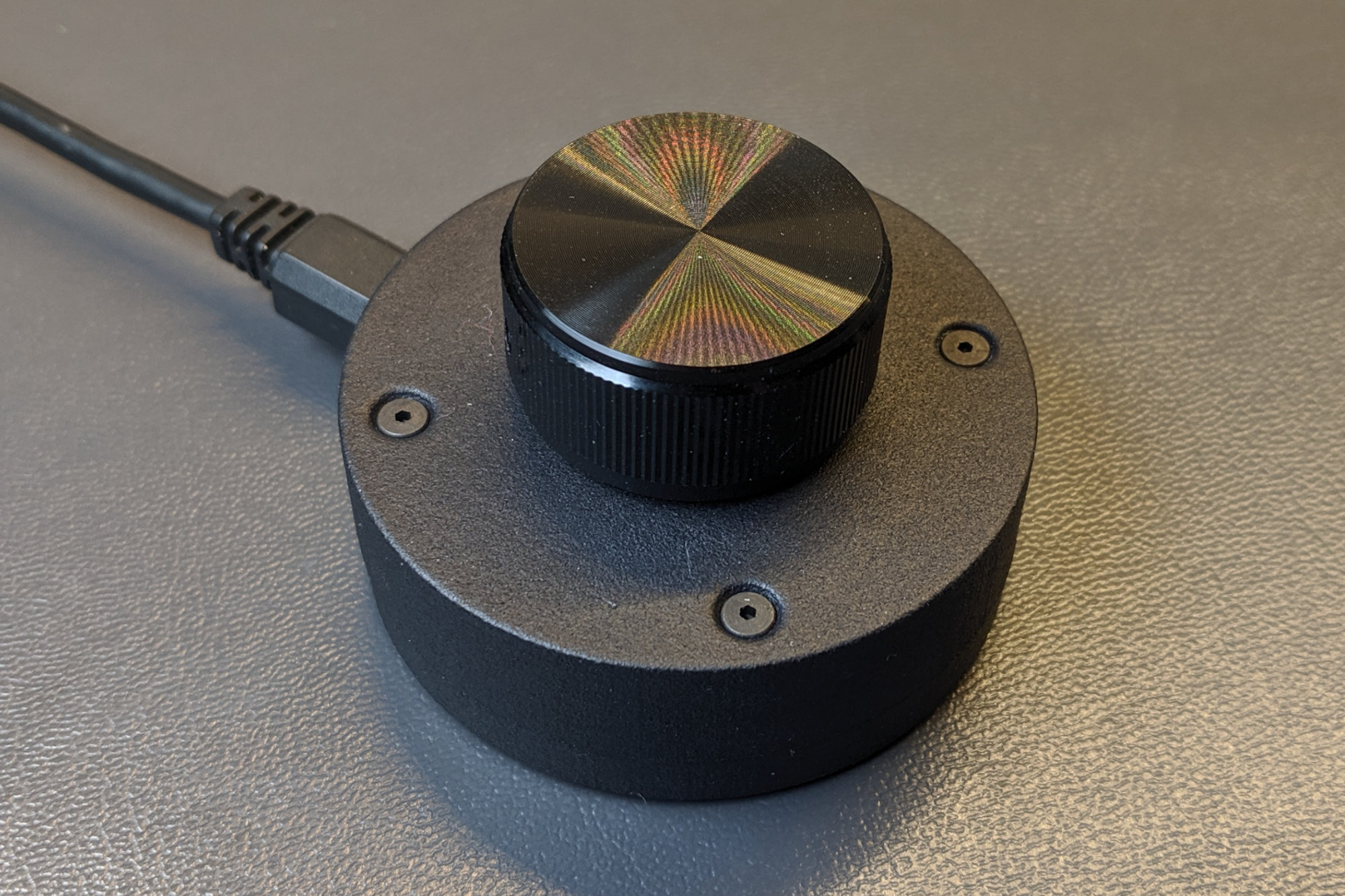
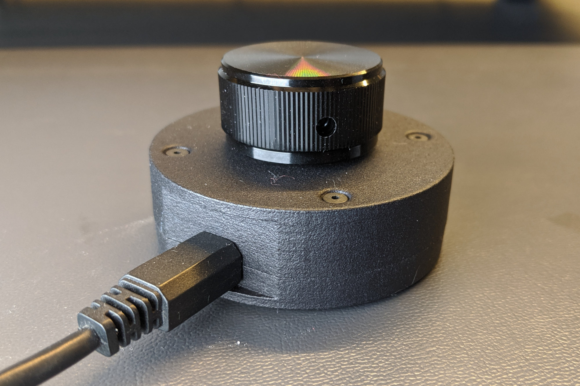
The completed USB volume knob. The 3D printed enclosure houses a custom board design, a PIC16F1459 microcontroller, and an optical encoder. The knob itself is an aluminum off-the-shelf component from TE Connectivity.
The PIC16F1459 is proving to be quite the versatile part when it comes to building USB devices. Previously, I’ve used it to upgrade my giant keyboard, various flavors of one-key keyboards, a USB-controlled industrial stack light, and an annoying CAPS LOCK warning buzzer. In this project, I’m going to use the PIC16F1459 to build a USB volume knob that works similarly to the volume keys on some USB keyboards. Read on to find out more about the design of the USB volume knob.
Enclosure Design
Design Inspiration and Criteria
Believe it or not, I designed the enclosure for this project before I ever even thought about building a USB volume knob. A few months ago, I set out to to design a generic enclosure that was somewhat roomy that I could use for any small project. The volume knob just happened to be the first project to come along after designing the generic enclosure.
Close up of the notch and connectors.
I thought about enclosures I designed in the past and a few elements of two enclosures in particular struct me as unique and something I should bring forward to my generic enclosure design. The first was the round form factor and the rear panel notch on the USB stack light controller base. These are shown in the photo of the stack light controller above.
If you look closely, you can see the overlapping lips on each half of the enclosure in this photo.
The second was the way the overlapping lips worked to seal the two halves of the PIC24 DMX RGB light together. If you look closely, you can see these in the photo of the light’s enclosure above.
After deciding on these key design elements, I narrowed down a few other design criteria:
- The enclosure should bolt together with 2-56 threaded black oxide screws and nuts.
- The enclosure should be 0.75 inch tall since this was the largest commonly available 2-56 thread black oxide screw length.
- The enclosure would be 60 mm in diameter.
- The flat edge of the board that would accommodate any necessary connectors would be 24 mm wide. 24 mm easily allows for a micro USB connector or USB C connector plus a second small connector or reset button,
- The enclosure walls would be 1.5 mm thick.
- The circular overhangs above and below the notch would be 2 mm thick to imply the enclosure is thicker and sturdier than it really is.
Parametric Modeling
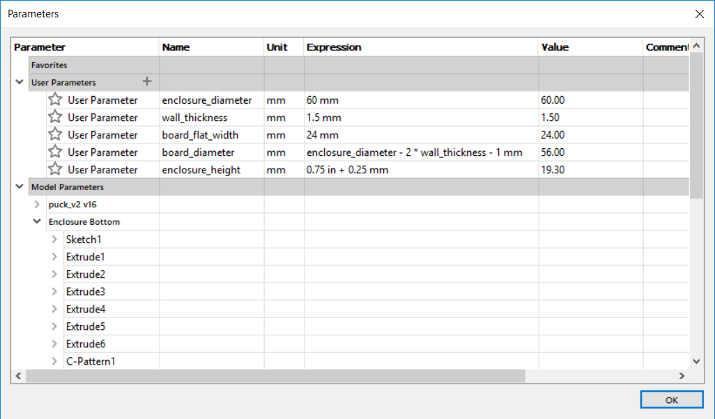
Parameters used to control the size of the enclosure.
Since this was a generic enclosure being designed for a project that doesn’t exist yet, it’d be great to be able to resize the enclosure later based on the actual needs of the project. Fortunately Fusion 360 supports parametric modeling. With parametric modeling, you define a list of parameters and their values. Instead of specifying a fixed value when drawing a feature in the model, you use the name of the parameter instead. Now when you go back to the table and change the parameter’s value, the model will automatically update and resize based on the new value.
The list of parameters and their values I used for this enclosure is shown in the photo above. When I sketched the circle that became the base of the model, I entered “enclosure_diameter” for the diameter of the circle rather than “60 mm.” Now if I decide I want a larger enclosure, I can go back to the table and change the expression for the enclosure_diameter from “60 mm” to “70 mm” and the base will magically grow to 70 mm in diameter. Another cool thing is expressions can be chained like the calculation of the board diameter above which is based on the enclosure diameter, the wall thickness, and a small offset.
Parametric modeling can be difficult to get right. It takes a bit of planning and foresight to get it right. The enclosure bottom seems to work OK. For some reason, the enclosure top doesn’t move its screw holes correctly when the diameter is changed and the enclosure_height doesn’t really work at all. I may fix this in a later version of the enclosure design. I called it good enough for now though and moved on.
Enclosure Bottom
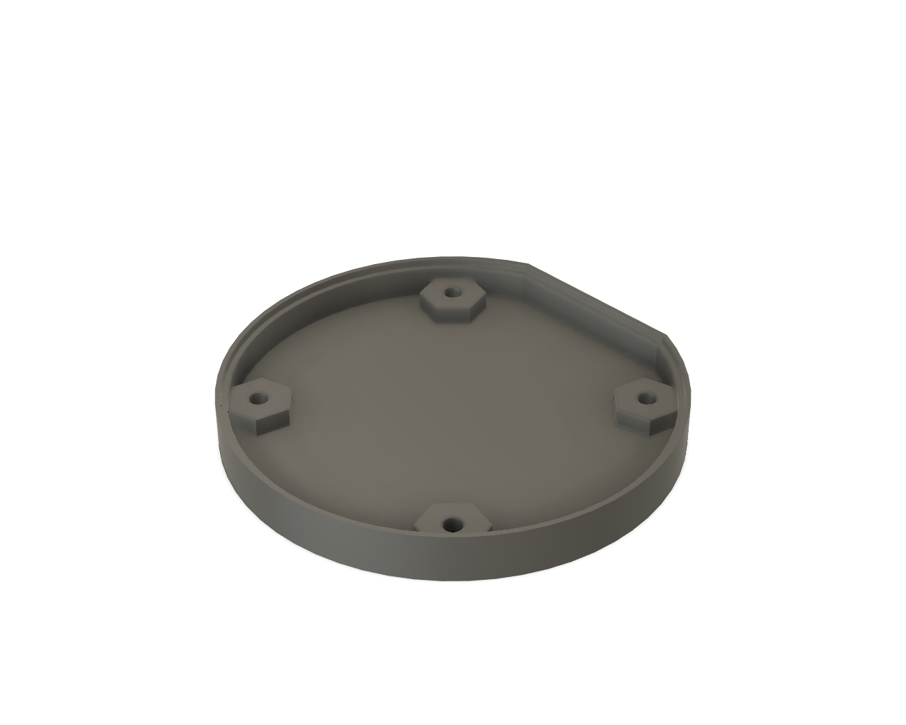
Interior view of the bottom half of the enclosure.
The photo above shows the interior of the bottom half of the completed enclosure. The board rests on top of the hexagonal extrusions that hold the hex nuts.
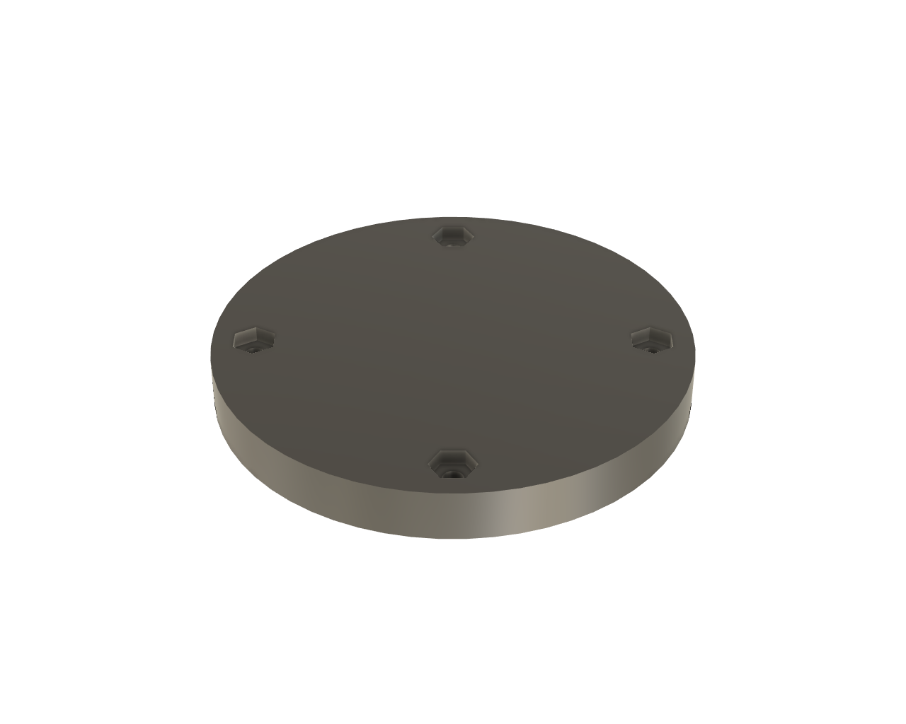
Exterior view of the bottom half of the enclosure.
The photo above shows the exterior of the bottom half of the completed enclosure. The hexagonal holes hold the hex nuts that secure the two halves of the enclosure together.
Enclosure Top
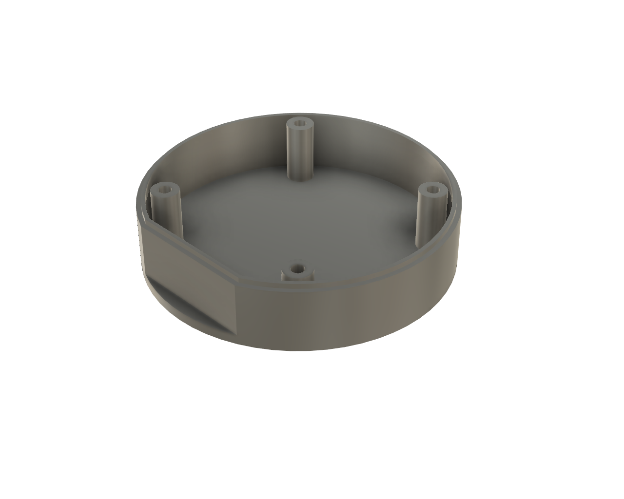
Interior view of the top half of the enclosure.
The photo above shows the interior of the top half of the completed enclosure. The screws that hold the enclosure together run through the center of the hollow posts. The ends of the hollow posts hold the circuit board in place. The flat portion notched out of the rear of the enclosure is very visible in this view.
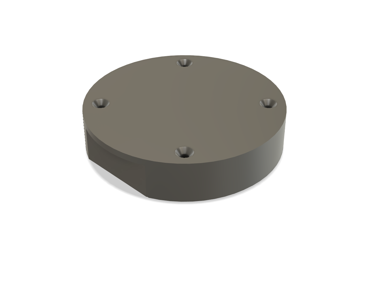
Exterior view of the top half of the enclosure.
The photo above shows the exterior of the top half of the completed enclosure. The holes are tapered so that the flat head screws lay flush with the top of the enclosure.
That’s the finished generic version of the enclosure. Once we’ve selected an encoder and knob, we’ll add a hole for the encoder as well as a hole for a female micro USB B connector.
Creating and Exporting a Board Outline
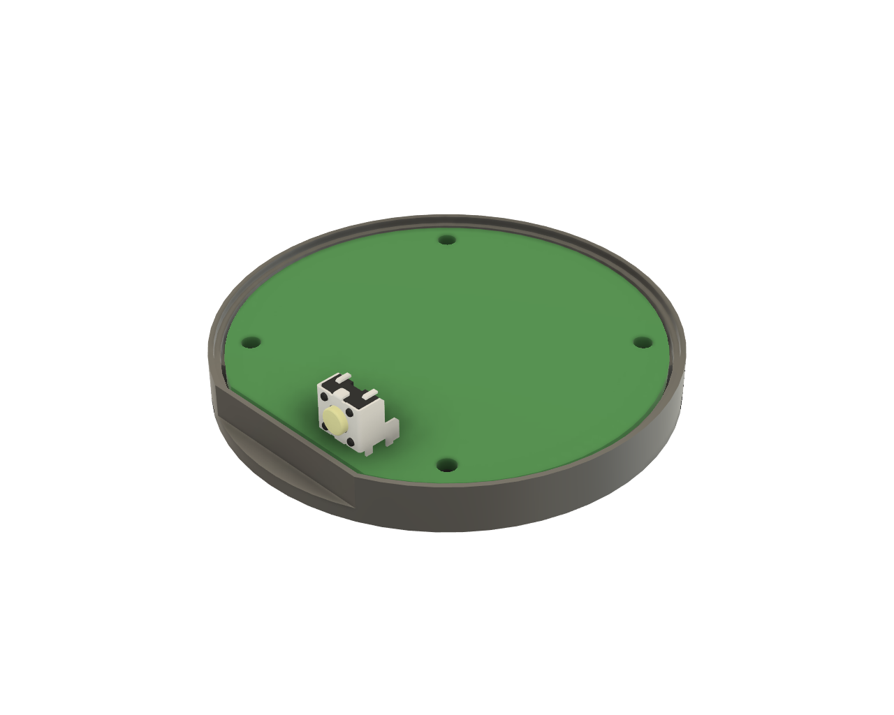
A generic circuit board located inside the enclosure. I added a 3D model of a right-angle tactile switch to see how a reset button might fit inside the enclosure.
Since this was a generic enclosure design, it only made sense to have an empty board outline I could use a starting point when designing various boards to fit inside the enclosure.
I constructed a plane on top of the hex standoffs then created a sketch on that plane. I projected the interior of the enclosure and offset it by 0.5 mm away from the walls of the enclosure to create the board outline. I also need to create keepouts for the hex standoffs and circular posts that contact the board inside the enclosure. I projected these from the bottom and top of the enclosure into the sketch as well.
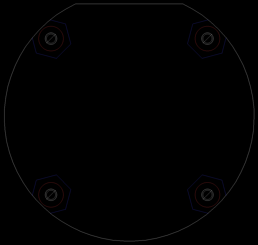
The completed board outline in Eagle PCB. The white outline is on the Dimension (20) layer. The hex and round keep out areas are on the blue bKeepout (40) and red tKeepout (39) layers respectively.
Once the sketch was completed, I exported it as a DXF file from Fusion 360 then imported it into the dimension layer in Eagle PCB. I moved the hex standoff lines to the bottom keepout layer and the round standoff lines to the top keepout layer. I left the board outline on the dimension layer. The DXF export and import wasn’t perfect so I had to patch up the board outline some on the dimension layer. Finally, I added the holes for the 2-56 screws and saved the file as an Eagle BRD file to use as a starting point for any designs utilizing the enclosure.
Selecting an Encoder
A tweet from one my co-workers was the inspiration to build a USB volume knob based on the work I’d done on the small keyboards and caps lock warning buzzer. Turning a variable resistor would not work for a USB volume knob though because a variable resistor outputs an absolute resistance / position value and there is not a USB HID command to set the volume to a fixed level. You can turn the volume down, you can turn the volume up, and you can toggle mute with USB HID. That’s it.
Also, a variable resistor has fixed end points in its rotation. Even if I could hack something to detect which way the variable resistor was being turned and send the correct USB HID commands to the computer, eventually I’d hit an endpoint in the knobs rotation and that endpoint would likely not be aligned with the lowest volume or highest volume setting on the computer.
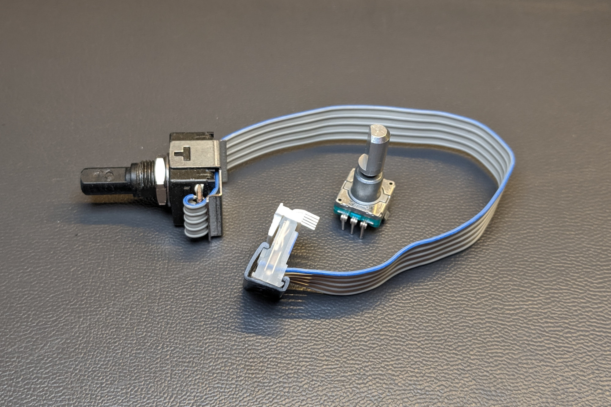
Two fundamentally different encoder examples.
I needed a device that could signal the volume to go up when turned one direction and that could signal the volume to go down when turned the other direction. Also pushing the knob should toggle mute. Fortunately such a device exists–the rotary encoder. I’ve heard them called incremental encoders, rotary pulse generators, or simply encoders. These come in a bunch of different varieties.
The photo above shows two examples. The one with the ribbon cable is an optical rotary encoder with a quadrature encoded output. The smaller one is a mechanical rotary encoder that closes different switch contacts based on CW or CCW rotation of the shaft. The optical encoder is over $30. The mechanical encoder is closer to $3.
As an aside, the optical encoder pictured above has been in production for over 30 years. It was originally developed within the test and measurement division of HP for use on the front panels of their test equipment. When Agilent split off from HP in 2000, the production of the encoder went to Agilent. The encoder then went to Avago in the Agilent-Avago split in 2015. It’s currently sold by Broadcom after the Avago acquistion of Broadcom and their subsequent name change.
Here are some key parameters to be aware of when selecting an encoder:
- Shaft size: 1/4-inch (6.35 mm) and 6 mm are the most common sizes. Shaft size needs to match the diameter of the hole in the center of the chosen knob.
- Shaft shape: Either round or D shaped. Round works. D shaped is easier to lock into place and prevent rotation of the knob on the shaft.
- Shaft length: The value is all over the place. It’s important that the locking screw on the chosen knob can make solid contact with whatever length shaft is chosen. It’s also aesthetically important that the shaft is not too long otherwise the knob will bottom out and look way too far away from the chassis.
- Smooth or with detents: Smooth encoders rotate freely. Encoders with detents click into place after each change in output state.
- Optical or mechanical: Optical encoders have longer lifetimes, offer more pulses per revolution, and are more expensive. Mechanical encoders are the opposite.
- Number of pulses per revolution: How many pulses does the knob generate in one revolution. 16, 32, 120, and 256 are common values. Some specialized encoders for motor shaft positioning applications generate even more.
- Encoding: quadrature / gray scale or discrete pulse per direction. We’ll get into quadrature / gray scale encoding in the software section below.
- Integrated switch: Some encoders have an integrated pushbutton switch; others don’t.
- Supply voltage: Optical encoders typically run from a specific supply voltage and have open-drain / open-collector outputs. Mechanical encoders are a bit more flexible in terms of acceptable voltages.
- Panel mount or board mount. Panel mount encoders have threaded stems and mount to the panel using a hex nut. Board mount encoders solder directly to the board. The distance between board and enclosure and encoder and knob all have to be considered during design with either type. I generally find board mount encoders to be less flexible in terms of positioning than panel mount encoders.
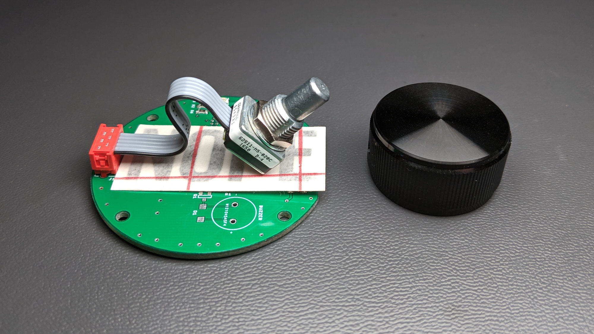
The Grayhill 62S11-M5-020C encoder used for this project. The sticker is leftover from another project and was used to keep the encoder from shorting to the board during software development.
I picked the Grayhill 62S11-M5-020C encoder that’s shown in the photo above. It has the following attributes:
- 1/4″ diameter D shaft.
- Detented with 32 pulses per revolution.
- Optical with quadrature encoding and an integrated switch.
- Panel mount with a short ribbon cable and small connector.
All this goodness was not cheap. The encoder goes for about $45 at quantity one.
Selecting a Knob
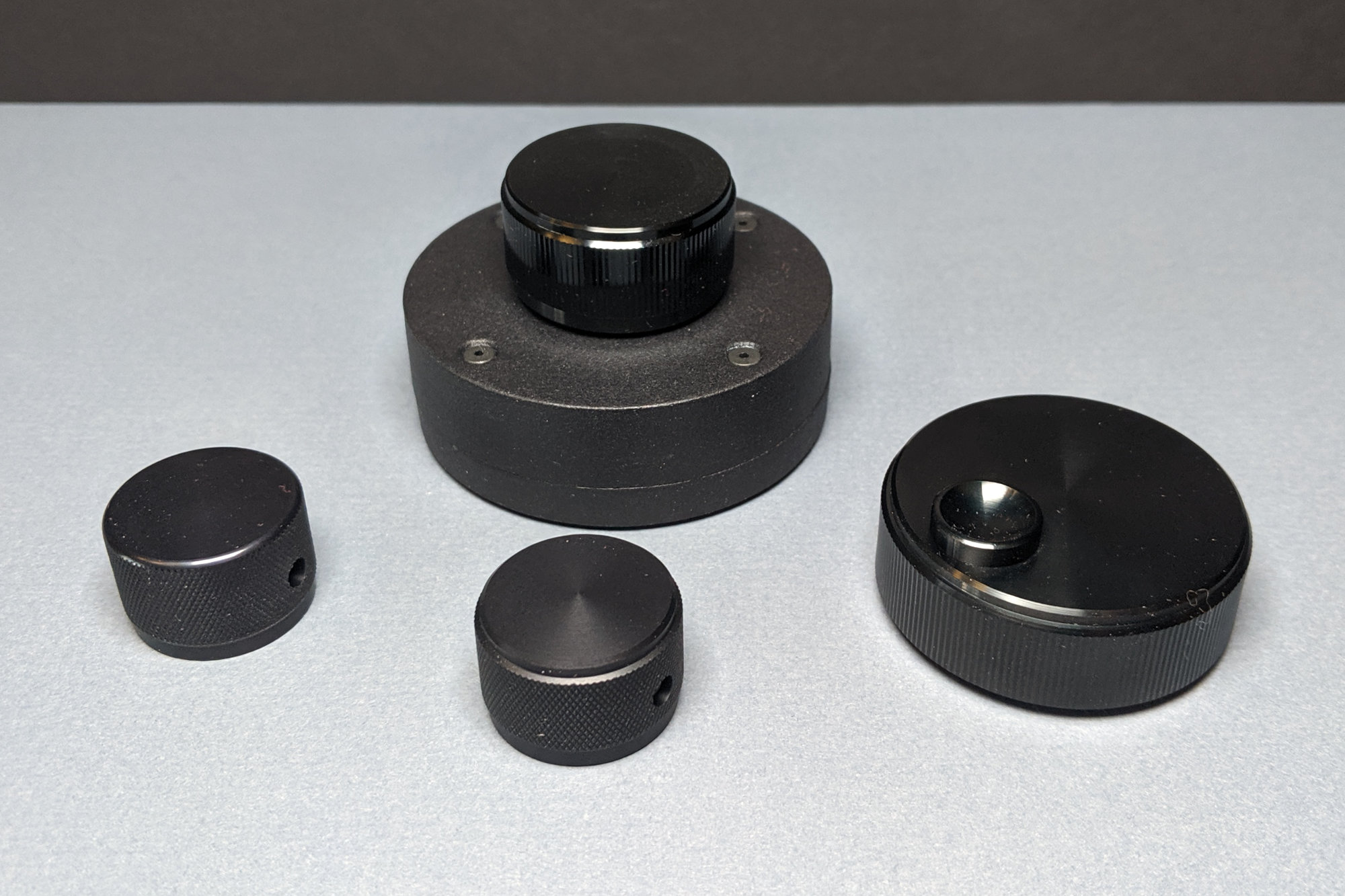
Three alternative knob options for the USB volume knob.
After selecting an encoder, the next step was to select a knob. I need a knob to fit a 1/4″ shaft and I wanted metal knob. I narrowed down to the four options shown in the picture above. The two larger knobs are made by TE Connectivity. They have a glossy finish. The two smaller knobs are made by Kilo International. They have a matte finish.
My favorite knob is the one front and center in the photograph but I decided it was too small compared to the enclosure. The knob I ultimately selected and is on the USB volume knob in the photo above is TE Connectivity part # KN1251B1/4 and sells for about $15. The runner up knob is Kilo International part # OEDNI-90-4-5 and sells for about $7. I’m definitely going to have to build something in the future that uses a few of the Kilo International knobs.
Finishing the Enclosure Design
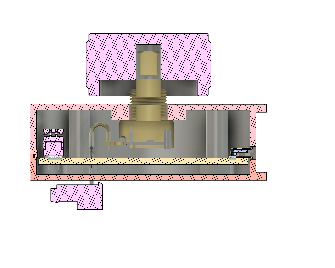
Section analysis showing the vertical alignment of the encoder within the enclosure.
Now that I had a knob and encoder picked out, it was time to return to the enclosure design. The encoder has a 3/8-32 thread and requires a 0.3970″ hole (PDF link). I created a hole centered on the top half of the enclosure with this diameter then it was time to think about the vertical alignment of the enclosure, circuit board, encoder, and knob.
Fortunately Grayhill had a 3D model of their encoder and TE Connectivity had a 3D model of their knob. I imported these into the enclosure design and used the joint tool to place the encoder in the hole and to place the knob on the end of the encoder shaft. The Grayhill 3D model wasn’t an exact match so there’s a rogue connector and cable protruding outside the enclosure but that’s OK for now.
Fusion 360’s section analysis tool allowed me to see a cutaway view of how the knob, encoder, PCB, and enclosure fit together. I played with the alignment until I found something where there was enough clearance between the knob and the enclosure to allow the integrated push button in the encoder to be pressed.
This ultimately required the encoder to be recessed 4.5 mm below the top of the enclosure and the knob to be elevated 1/16″ above the end of the shaft of the encoder. I could use washers to satisfy the former requirement. Instead I bulked up the 3D printed material between the encoder and enclosure to the required thickness. To satisfy the latter requirement, I placed a 1/16″ spacer with an outside diameter of 1/4″ into the knob before mounting it on the encoder’s shaft. Kind of a kluge but it works well.
I added the cutout for the micro USB B connector to the rear of the enclosure using the same technique I used when making connector cutouts on the DMX-controlled RGB LED light. The final version of the 3D printed enclosure with the micro USB B connector cutout and the encoder and knob mounted is shown the image below. I then generated the STL files and sent them for 3D printing at Sculpteo using HP’s Multi Jet Fusion 3D printing technology.
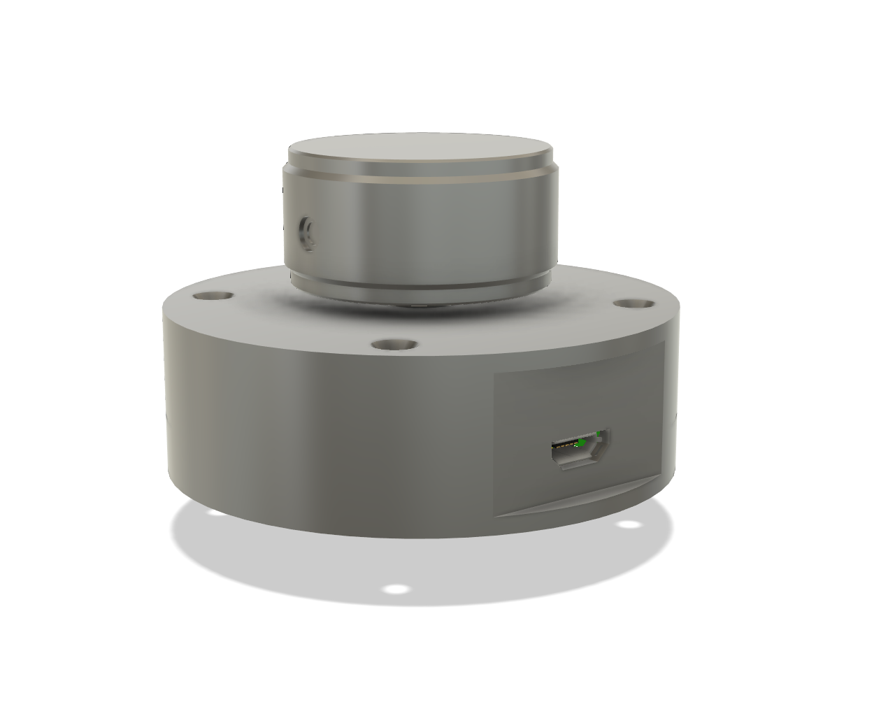
Finished enclosure design.
Designing the Electronics and Board
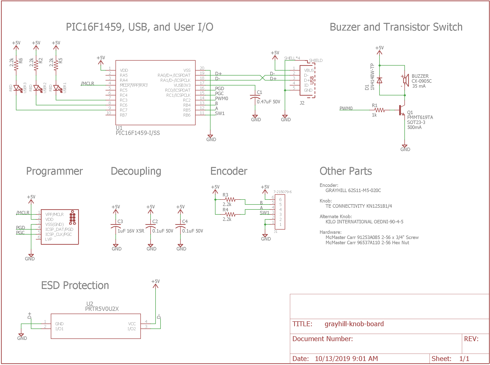
Completed schematic.
The schematic for the electronics is shown in the image above. It’s identical to the schematic for the updated version of the Annoying CAPS LOCK Warning Buzzer except for the addition of a connector for the Grayhill optical rotary encoder and a few more LEDs.
The Grayhill encoder requires +5V DC to power the infrared light sources inside the encoder. It has open-drain / open-collector outputs and requires 2.2k pullup resistors on its CH A and CH B outputs to function. The encoder’s integrated push button switch uses the PIC’s internal weak pullup function so no pullup resistor is required on the switch output signal.
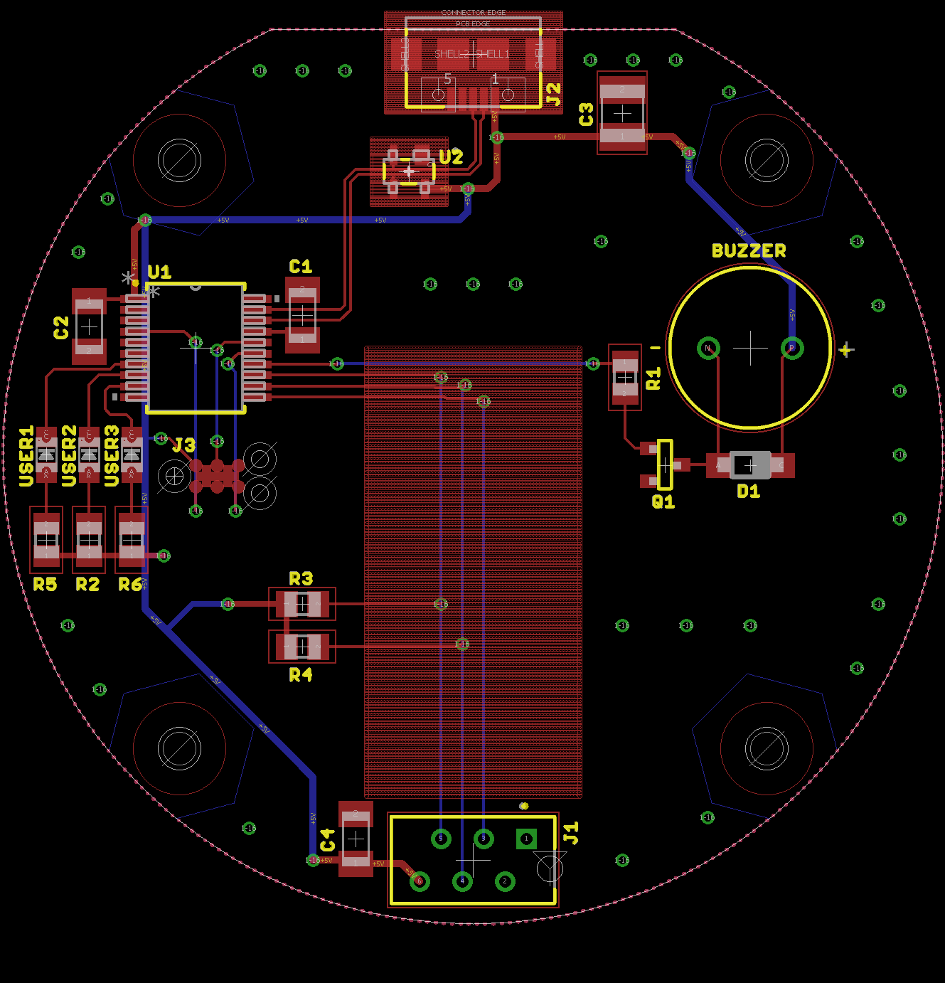
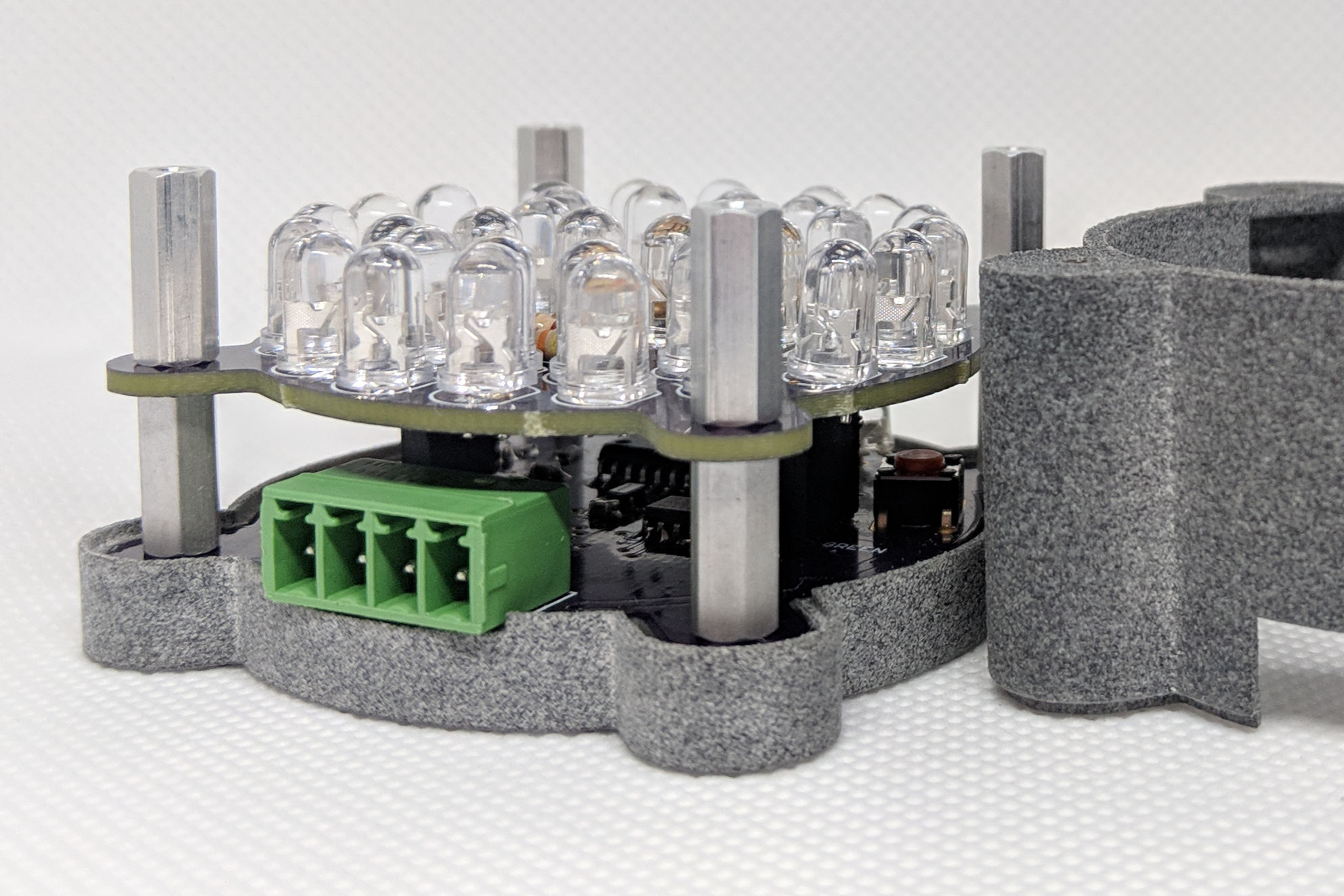
Completed board.
The USB volume knob board is 56 mm in diameter. It is absolutely roomy compared to the 1″ x 1″ boards used for the caps lock warning buzzer and assorted one key keyboards. As a result, the layout was significantly easier and faster to finish.
I started with the generic board outline file I created while designing the enclosure. On that board outline I placed the critical components like the USB connector, the encoder connector, and the ESD suppression diodes first.
I placed the rest of the components next while leaving a big open area in the center to avoid any components making contact with the metallic base of the encoder or interfering with the folding of the encoder’s ribbon cable. After placing all the components, it was time to route the board.
I created a ground plane on each side of the board then connected the two ground planes using lots of vias through the board. Horizontal traces run on the front side of the board and vertical traces run on the rear. The +5V power is routed where its needed using traces. The completed and stuffed board is shown in the photo below.
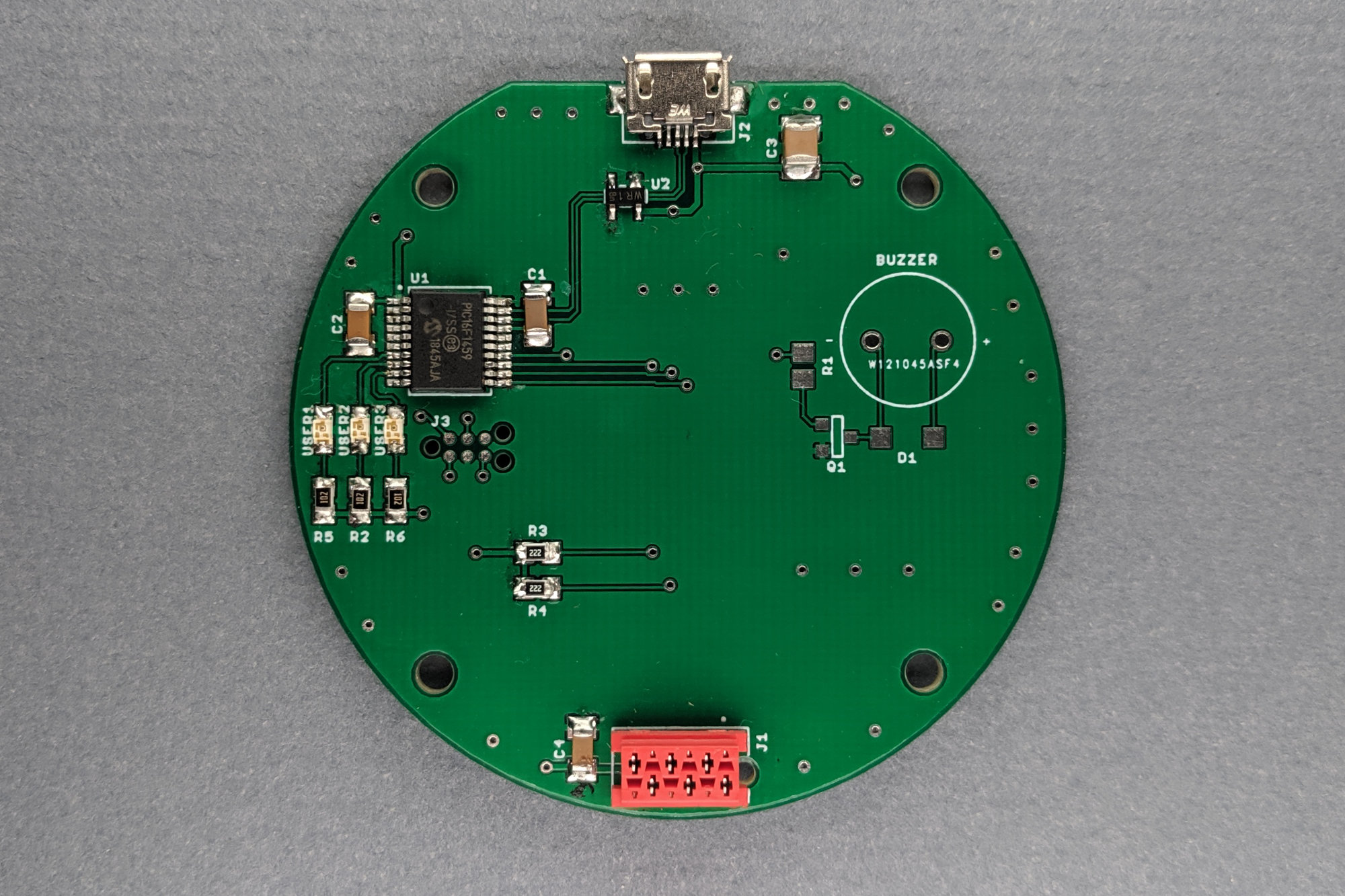
The completed and stuffed circuit board. I left the buzzer off for now.
Software
I did have one slight snag while building this project: the software. Just because volume keys are on many USB keyboards doesn’t mean the volume keys function like the rest of the keys on the keyboard. The USB HID spec treats the volume keys quite differently. As a result, the software I used on the one key keyboards and caps lock warning buzzer was going to require some pretty arcane (if USB HID is not your thing) modifications to control the computer’s volume.
USB HID Report Descriptors
During device enumeration, the connected USB device tells the USB host what type of device it is. If it is a USB HID device, the device also has to tell the host the types and formats of reports it will send to the host and the types and formats of reports it expects from the host. This is done using a USB HID report descriptor.
The USB HID report descriptor is built using codes from the USB HID specification and a supplementary document called the USB HID usage tables. The USB HID report descriptor provides the host with enough information to parse USB input reports or to create USB output reports.
This offloads a lot of complexity from the device to the host. The host must be able to deal with arbitrarily formatted input reports from USB HID devices. It must also be able to create arbitrarily formatted output reports to send to USB HID devices. There’s no guarantee that different USB HID devices that perform similar functions will have identical or even similarly formatted input and output reports.
The code below shows the USB HID report descriptor that my small one key keyboards and the caps lock warning buzzer use. It asks the host to send an output report with the status of the five common LEDs (Num Lock, Scroll Lock, Caps Lock, etc.) and three padding bits. It also tell the host that the device will send the state of the eight modifier keys followed by up to six keys from the key code chart when polled by the host.
const struct{uint8_t report[HID_RPT01_SIZE];}hid_rpt01={
{   0x05, 0x01,                    // USAGE_PAGE (Generic Desktop)
    0x09, 0x06,                    // USAGE (Keyboard)
    0xa1, 0x01,                    // COLLECTION (Application)
    0x05, 0x07,                    //   USAGE_PAGE (Keyboard)
    0x19, 0xe0,                    //   USAGE_MINIMUM (Keyboard LeftControl)
    0x29, 0xe7,                    //   USAGE_MAXIMUM (Keyboard Right GUI)
    0x15, 0x00,                    //   LOGICAL_MINIMUM (0)
    0x25, 0x01,                    //   LOGICAL_MAXIMUM (1)
    0x75, 0x01,                    //   REPORT_SIZE (1)
    0x95, 0x08,                    //   REPORT_COUNT (8)
    0x81, 0x02,                    //   INPUT (Data,Var,Abs)
    0x95, 0x01,                    //   REPORT_COUNT (1)
    0x75, 0x08,                    //   REPORT_SIZE (8)
    0x81, 0x03,                    //   INPUT (Cnst,Var,Abs)
    0x95, 0x05,                    //   REPORT_COUNT (5)
    0x75, 0x01,                    //   REPORT_SIZE (1)
    0x05, 0x08,                    //   USAGE_PAGE (LEDs)
    0x19, 0x01,                    //   USAGE_MINIMUM (Num Lock)
    0x29, 0x05,                    //   USAGE_MAXIMUM (Kana)
    0x91, 0x02,                    //   OUTPUT (Data,Var,Abs)
    0x95, 0x01,                    //   REPORT_COUNT (1)
    0x75, 0x03,                    //   REPORT_SIZE (3)
    0x91, 0x03,                    //   OUTPUT (Cnst,Var,Abs)
    0x95, 0x06,                    //   REPORT_COUNT (6)
    0x75, 0x08,                    //   REPORT_SIZE (8)
    0x15, 0x00,                    //   LOGICAL_MINIMUM (0)
    0x25, 0x65,                    //   LOGICAL_MAXIMUM (101)
    0x05, 0x07,                    //   USAGE_PAGE (Keyboard)
    0x19, 0x00,                    //   USAGE_MINIMUM (Reserved (no event indicated))
    0x29, 0x65,                    //   USAGE_MAXIMUM (Keyboard Application)
    0x81, 0x00,                    //   INPUT (Data,Ary,Abs)
    0xc0}                          // End Collection
};
Further complicating things, the volume control keys are not a part of the keyboard usage page in the HID usage tables. They’re part of a separate usage page called the consumer control usage tables. If we want to send volume control keys to the host, we need to send some HID usage codes from a different usage table than we used for the keyboard.
Unfortunately, there’s no way to mix the keyboard usage with the consumer usage in a single input report. This means our device needs to send one type of input report when a keyboard key is pressed and a second, different type of input report when the volume is adjusted. (Or we could do away with sending keyboard usage input reports altogether but I wanted to keep the caps lock status and did not want to preclude sending +/- key presses instead of volume up / volume down in the future.)
Telling the host our device is capable of sending two different USB input reports is done using USB HID collections. There’s already one USB HID collection in the code above. The code below builds on the code above and adds a second USB HID collection. Everything up to the start of the second USB HID collection in the code below is identical to the code above.
const struct{uint8_t report[HID_RPT01_SIZE];}hid_rpt01={
{   0x05, 0x01,                    // USAGE_PAGE (Generic Desktop)
    0x09, 0x06,                    // USAGE (Keyboard)
    0xa1, 0x01,                    // COLLECTION (Application)
    0x85, 0x01,                    //   REPORT_ID
    0x05, 0x07,                    //   USAGE_PAGE (Keyboard)
    0x19, 0xe0,                    //   USAGE_MINIMUM (Keyboard LeftControl)
    0x29, 0xe7,                    //   USAGE_MAXIMUM (Keyboard Right GUI)
    0x15, 0x00,                    //   LOGICAL_MINIMUM (0)
    0x25, 0x01,                    //   LOGICAL_MAXIMUM (1)
    0x75, 0x01,                    //   REPORT_SIZE (1)
    0x95, 0x08,                    //   REPORT_COUNT (8)
    0x81, 0x02,                    //   INPUT (Data,Var,Abs)
    0x95, 0x01,                    //   REPORT_COUNT (1)
    0x75, 0x08,                    //   REPORT_SIZE (8)
    0x81, 0x03,                    //   INPUT (Cnst,Var,Abs)
    0x95, 0x05,                    //   REPORT_COUNT (5)
    0x75, 0x01,                    //   REPORT_SIZE (1)
    0x05, 0x08,                    //   USAGE_PAGE (LEDs)
    0x19, 0x01,                    //   USAGE_MINIMUM (Num Lock)
    0x29, 0x05,                    //   USAGE_MAXIMUM (Kana)
    0x91, 0x02,                    //   OUTPUT (Data,Var,Abs)
    0x95, 0x01,                    //   REPORT_COUNT (1)
    0x75, 0x03,                    //   REPORT_SIZE (3)
    0x91, 0x03,                    //   OUTPUT (Cnst,Var,Abs)
    0x95, 0x06,                    //   REPORT_COUNT (6)
    0x75, 0x08,                    //   REPORT_SIZE (8)
    0x15, 0x00,                    //   LOGICAL_MINIMUM (0)
    0x25, 0x65,                    //   LOGICAL_MAXIMUM (101)
    0x05, 0x07,                    //   USAGE_PAGE (Keyboard)
    0x19, 0x00,                    //   USAGE_MINIMUM (Reserved (no event indicated))
    0x29, 0x65,                    //   USAGE_MAXIMUM (Keyboard Application)
    0x81, 0x00,                    //   INPUT (Data,Ary,Abs)
    0xc0,                          // End Collection

    0x05, 0x0C,                    // USAGE_PAGE (Consumer Devices)
    0x09, 0x01,                    // USAGE (Consumer Control)
    0xA1, 0x01,                    // COLLECTION (Application)
    0x85, 0x02,                    //   REPORT_ID
    0x05, 0x0C,                    //   USAGE_PAGE (Consumer Devices)
    0x15, 0x00,                    //   LOGICAL_MINIMUM (0)
    0x25, 0x01,                    //   LOGICAL_MAXIMUM (1)
    0x75, 0x01,                    //   REPORT_SIZE (1)
    0x95, 0x07,                    //   REPORT_COUNT (7)
    0x09, 0xB5,                    //   USAGE (Scan Next Track)
    0x09, 0xB6,                    //   USAGE (Scan Previous Track)
    0x09, 0xB7,                    //   USAGE (Stop)
    0x09, 0xCD,                    //   USAGE (Play / Pause)
    0x09, 0xE2,                    //   USAGE (Mute)
    0x09, 0xE9,                    //   USAGE (Volume Up)
    0x09, 0xEA,                    //   USAGE (Volume Down)
    0x81, 0x02,                    //   INPUT (Data, Variable, Absolute)
    0x95, 0x01,                    //   REPORT_COUNT (1)
    0x81, 0x01,                    //   INPUT (Constant)
    0xC0}                          // End Collection
};
The first thing this new, second USB HID collection does is tell the host we’re going to send codes from the USB HID consumer control usage tables. This is done using the USAGE_PAGE and USAGE instructions. Next, this input report will have an ID of 0x02. Then it tells the host we’re going to send the state of the track controls and volume controls and one padding bit. Lastly, it closes the collection with the end collection instruction. This forum post on Microchip’s website was invaluable in figuring out the modifications that were required to send the volume keys in a USB input report.
Another slight wrinkle is that if there is only one type of input report, the input report ID is not specified in the USB input reports sent from the device to the host. If there’s more than one type of input report, however, the input report ID must be specified in the USB input report. This means our USB input reports need to be bumped in length from eight bytes to nine bytes everywhere they’re referenced in our code.
If you’re really curious about all the code changes to support a second type of USB HID input report, I suggest doing a diff between the annoying caps lock warning buzzer source code and the USB volume knob source code. Source code for both devices is in my Github repositories.
Decoding the Encoder’s Quadrature Outputs

Truth table and waveform illustration from the Grayhill encoder data sheet.
If you look at OUTPUT A and OUTPUT B in the above diagram, you can see that OUTPUT B lags OUTPUT A by 90 degrees. This is called quadrature encoding. As a result, the outputs of the encoder looks like a gray code counter and only one output signal changes per click / move of the encoder.
To determine the direction the encoder is moving you need to know the last state of the two outputs and the current state of the two outputs. Based on the last state and the current state, you can determine if the encoder is being turned clockwise or counterclockwise.
For example, let’s start at position number 3 in the diagram above. A and B are both high. We save this state to a variable. Some amount of time later, we read the encoder again. If A and B are still both high, the encoder has not been turned. If however, A is now low while B is still high, the encoder has been turned one click clockwise. If however, A is still high while B is now low, the encoder has been turned one click counterclockwise.
To avoid missing encoder pulses, software must read the encoder at least twice as fast as the highest expected pulse rate. My software polls the encoder at a 1 kHz rate. This allows the encoder to be turned up to 500 pulses per second without missing a pulse. With a manually turned knob with only 32 pulses per revolution, that rate is acceptable. If you have a microcontroller capable of generating interrupts on the change of state of input pins, you can handle much higher rotational speeds.
The code to read the encoder and determine whether the volume needs to go up or down is shown below. The variable last_knob holds the last known state of the encoder’s outputs. The variable this_knobs is assigned the current state of the encoder’s outputs. The switch statement determines which way the knob is being turned and updates the signed variable value_knob up or down based on the direction the knob is turned.
#define S2_PORT  PORTBbits.RB5      // CHA
#define S3_PORT  PORTBbits.RB4      // CHB

void BUTTON_UpdateStates (void)
{
    ...
    // this_knob = { CHB, CHA }
    this_knob = (S3_PORT << 1) | S2_PORT;
    switch (last_knob) {
        case 0: if (this_knob == 1) { value_knob--; } else if (this_knob == 2) { value_knob++; } break;
        case 1: if (this_knob == 0) { value_knob++; } else if (this_knob == 3) { value_knob--; } break;
        case 2: if (this_knob == 0) { value_knob--; } else if (this_knob == 3) { value_knob++; } break;
        case 3: if (this_knob == 1) { value_knob++; } else if (this_knob == 2) { value_knob--; } break;
    }
    last_knob = this_knob;
}
Inside the code that responds to the USB bus’s input polling requests is code to see if value_knob is less than or greater than zero. This code is shown below. If it’s less than zero, it sets the volume_down bit in the USB input report that will be sent to the host computer. If it’s greater than zero, it sets the volume_up bit in the USB input report that will be sent to the host computer. There’s quite a bit of abstraction and redirection in this code since I did not attempt to simplify it any from the Microchip for Library Applications source code.
inputReport.report_id = 0x02;
if(BUTTON_IsPressed(BUTTON_USB_DEVICE_HID_KEYBOARD_KEY_0) == true) {
    inputReport.modifiers.media.mute = 1;
}
if(BUTTON_IsPressed(BUTTON_USB_DEVICE_HID_KEYBOARD_KEY_1) == true) {
    inputReport.modifiers.media.volumeDown = 1;
}
if(BUTTON_IsPressed(BUTTON_USB_DEVICE_HID_KEYBOARD_KEY_2) == true) {
    inputReport.modifiers.media.volumeUp = 1;
}
Inside the BUTTON_isPressed function below is the actual check to see if value_knob is positive or negative. The caller calls BUTTON_isPressed with the value BUTTON_S2 to see if the volume needs to be turned down. If it does, the function returns true and value_knob is incremented to mark that we’ve handled this volume down request from the user. The caller calls BUTTON_isPressed with the value BUTTON_S3 to see if the volume needs to be turned up. If it does, the function returns true and value_knob is decremented to mark that we’ve handled this volume down request from the user. BUTTON_S1 implements the mute function.
The incrementing and decrementing of the value_knob variable allows for the encoder to be turned faster than volume updates can be sent over the USB bus. Once the encoder stops turning, the USB bus will eventually catch up and value_knob will settle on zero. The code that generates the USB input reports might need to be updated to send a ‘0’ for all the mute / volume keys between presses for this to work properly.
bool BUTTON_IsPressed(BUTTON button)
{
    switch(button) {
        case BUTTON_S1:
            return ((state1 >= 2) ? true : false);
        case BUTTON_S2:
            if (value_knob < 0) {
                value_knob++;
                return true;
            }
            return false;
        case BUTTON_S3:
            if (value_knob > 0) {
                value_knob--;
                return true;
            }
            return false;
        case BUTTON_NONE:
            return false;
    }
    return false;
}
Program the Bootloader

An extremely staged photo of using the Tag-Connect cable to program the USB bootloader.
Up until this point, I had been using the MPLAB X IDE and my REAL ICE debugger to program and debug the firmware directly on the PIC16F1459. Now that the firmware was debugged, it was time to go to a more production oriented approach to programming and updating the USB volume knob firmware.
I used the MPLAB X IDE and my REAL ICE programmer to program a USB bootloader into the microcontroller. This allows updates to the firmware to be made directly over the USB bus without taking the USB volume knob apart and without using a dedicated programmer and programmer cable. This is the exact same USB bootloader I used on the one key keyboards and annoying caps lock warning buzzer.
Program the Firmware
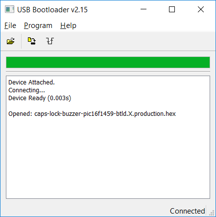
The main (and only) window of the Microchip Library for Applications USB Bootloader utility.
Once the bootloader was programmed into the PIC16F1459, I could update the USB volume knob firmware using the Microchip Library for Applications (MLA) USB Bootloader Utility. A screenshot of the utility is shown above. The process is as follows:
- Launch the MLA bootloader utility from the MLA install directory.
- Hold down the knob while plugging the USB volume knob into the USB port on the PC.
- Wait for the device attached and device ready messages as shown in the dialog box above.
- Click the open button in the GUI and select the .hex file from the dist directory inside the USB volume knob firmware directory.
- Click the program button to program the firmware into the USB volume knob.
- Click the reset button to reset the PIC and launch the application firmware. You can also unplug the USB volume knob then plug it back into the PC. Do not hold down the knob this time.
- Test the firmware update by turning the knob to change the volume and pressing the knob to mute / unmute the volume.
Testing
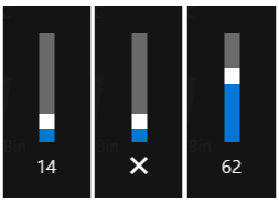
Turn the knob and you should see the volume go up and down. Press the knob and you should see the volume mute and unmute.
Test the knob before assembling the knob into the enclosure. Turn the knob to change the volume and press the knob to mute / unmute the volume.
Assembly

Parts and tools required for assembly. Note how the encoder’s ribbon cable is accordion folded into place.
Assembly went pretty smoothly. First mount the encoder to the top of the enclosure using the hardware included with the encoder. Next accordion fold the ribbon cable as shown in the photograph above. Connect the encoder cable to the circuit board then press the circuit board against the top of the enclosure. While holding the circuit board in place, thread a few screws through the top of the enclosure and fit the bottom of the enclosure over the screws. Insert the nuts into their recesses on the bottom of the enclosure and tighten all four screws using a 3/64″ or 0.050″ hex driver.
A top view of the assembled USB volume knob is shown in the photo below.
The completed USB volume knob project. It uses an off-the-shelf knob and a PIC16F1459 microcontroller. The enclosure is 3D printed.
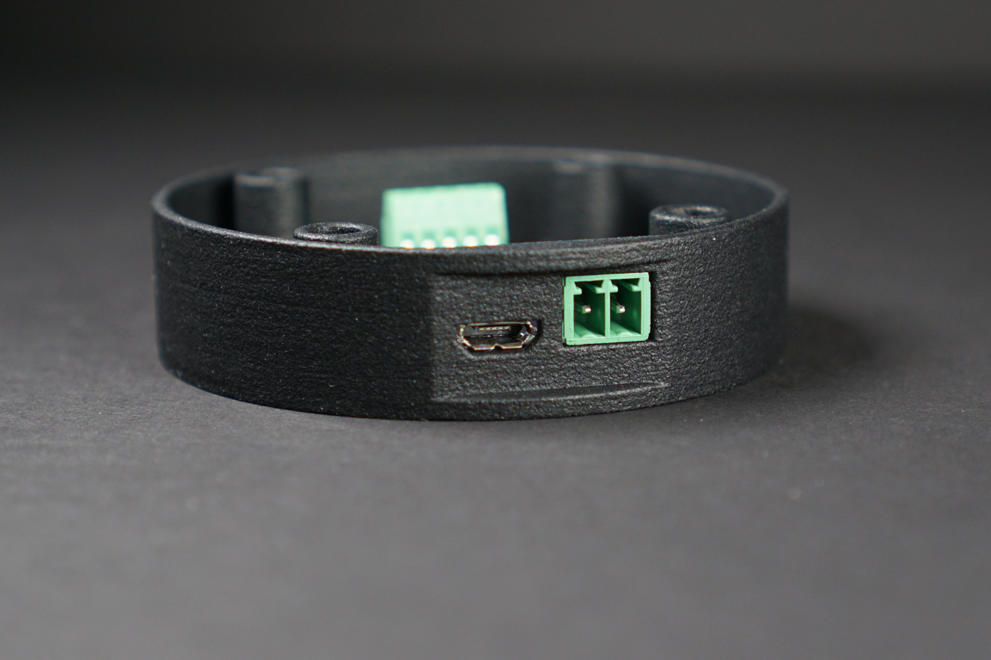
A side view of the rear of the assembled USB volume knob is shown in the photo below.
Flat section on the rear of the enclosure to accommodate the micro USB connector.
My desk is kind of slick. I dug through the junk drawer in the kitchen to find some rubber bumpers to place on the bottom of the USB volume knob to keep it in place while turning it. I only had two bumpers left. That’d be kind of wobbly so I cut the waste material surrounding the two remaining bumpers to size then stuck it on the bottom of the USB volume knob instead:
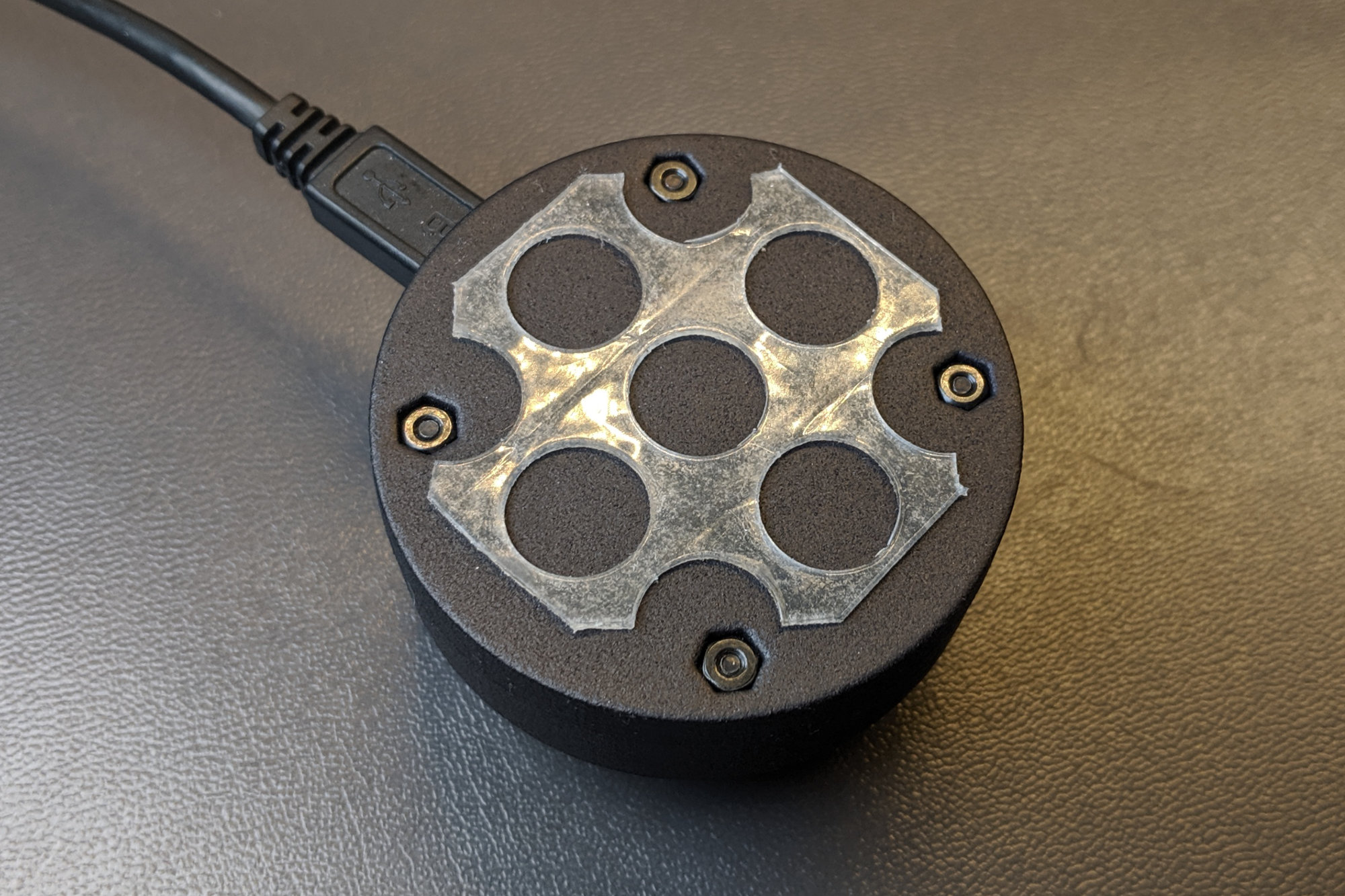
Rubber stuck to bottom of enclosure to keep it from sliding on my desk.
Design Files
Design files are available for the enclosure, board, and software in my Github repository for the project.
Resources
The following online resources were helpful while figuring out the needed USB input report descriptors to report desired volume changes to the PC:
- This Microchip forum post:
https://www.microchip.com/forums/m618147.aspx - This tutorial on USB HID Report Descriptors:
https://eleccelerator.com/tutorial-about-usb-hid-report-descriptors/
Readers may also find the following resources helpful:
- A good description of the USB HID setup process:
http://kevincuzner.com/2018/02/02/cross-platform-driverless-usb-the-human-interface-device/ - The USB HID Landing Page:
https://www.usb.org/hid - The USB Device Class Definition for Human Interface Devices (HID):
https://www.usb.org/sites/default/files/documents/hid1_11.pdf - The USB HID usage tables:
https://www.usb.org/sites/default/files/documents/hut1_12v2.pdf