
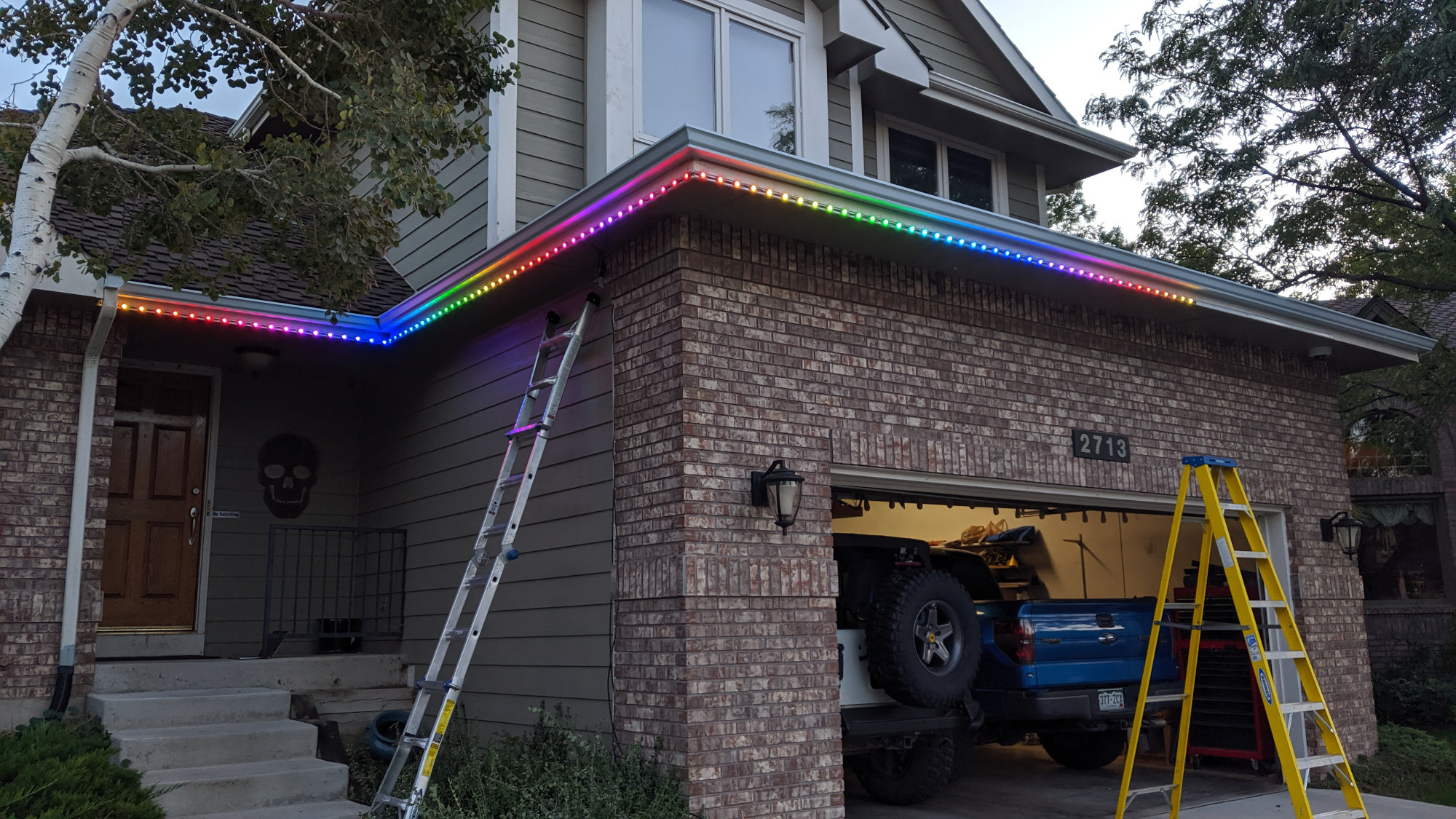
Hanging a bunch of iColor Flex LMX string lights on the house for Halloween. These are quite visible even though it’s still daylight out!
Back in the early 2000’s–at least a decade before there were Neopixels or WS2812b LEDs–Color Kinetics introduced flexible color changing LED string lights. Each string contained fifty RGB color changing nodes. Each node contained an RGB LED and a custom ASIC. The nodes were strung along at either 4″ or 12″ spacing along a three conductor cable. The cable connected back to a power data supply that powered the nodes and translated the light level data from either DMX-512 or Ethernet UDP packets into the proprietary protocol used by the nodes. Today we’re going to reverse engineer that proprietary protocol.
Branding
Color Kinetics is big into branding and trademarks. They call their RGB LED string lights iColor Flex, the ASIC inside each node is a Chromasic, and the protocol they use to communicate is called the Chromasic protocol. The biggest differentiators between all the different products are the color of light emitted, RGB or white, and the diameter of the node, 15 mm or 35 mm.
iColor Flex SL
Three iColor Flex SL nodes.
The original iColor Flex product was iColor Flex SL. Each node was a dot about 15 mm in diameter and contained a single RGB LED. These were available in eight different configurations by selecting from among the following options:
- Black wire and nodes or white wire and nodes.
- Nodes spaced at 4″ or 12″.
- Dome or cone diffuser.
- Clear or translucent diffuser.
The iColor Flex SL product ran from 7.5 V and was advertised as capable of producing 68 billion color combinations. Each node used three channels for control: one for red, one for green, and one for blue. A twenty foot leader cable extended from the first node in the string and plugged directly into a power data supply. The power supply connector was permanently attached to the leader cable.
iColor Flex SLX
The second product was iColor Flex SLX. Each node was a dot about 35 mm in diameter and contained three RGB LEDs. These were available in eight different configuration too except the choices for the shape of the diffuser were now dome or flat. These ran from 12 V, used three control channels, and came with an attached twenty feet leader cable that plugged directly into a power data supply.
iColor Flex MX, LMX, MX gen2, and LMX gen2

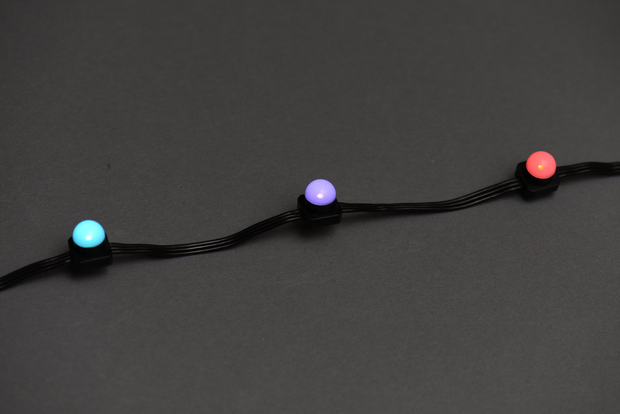
iColor Flex LMX nodes.
As RGB LEDs continued to get brighter, Color Kinetics refreshed their product line. The small nodes became iColor Flex MX and MX gen2. The large nodes became iColor Flex LMX and LMX gen2. In addition the large nodes now contained six RGB LEDs instead of three and ran from 24 V instead of 12 V.
Another big change introduced with these products was a detachable leader cable that could be shortened to fit the user’s application. The string of nodes now shipped with a short three foot pigtail that plugged into a leader cable that connected back to the power supply through a dongle. We’ll cover the dongle and leader cable in detail in a following section.
Fixed and Variable Color Temperature White Strings
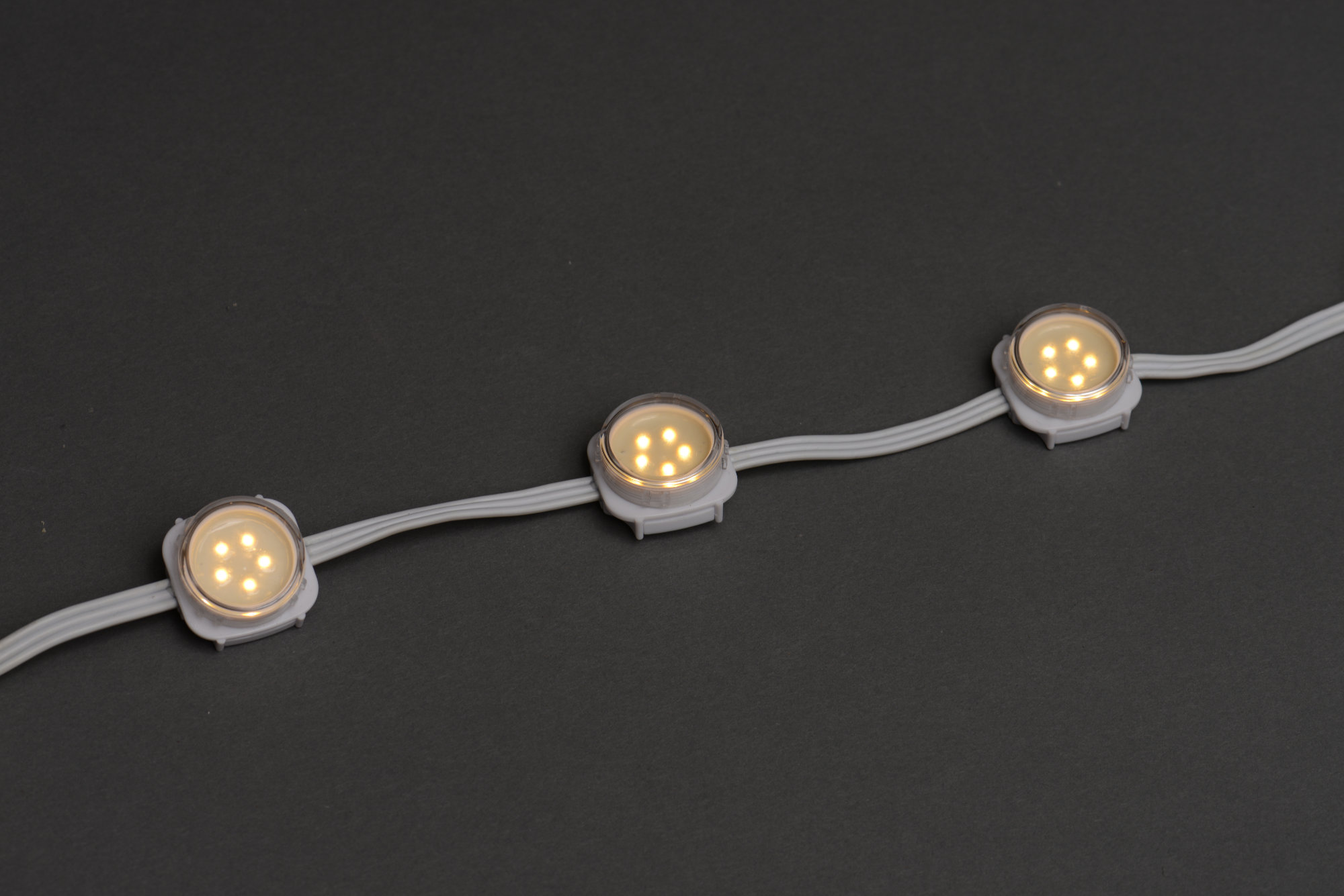
eW Flex SLX nodes.
Color Kinetics also makes their string lights in fixed and variable color temperature white light versions. The fixed color temperature versions are branded as eW Flex or Essential White Flex. These contain one or five white LEDs and are available in a variety of fixed color temperatures. Each node requires three control channels. The first channel controls the brightness of the node. The second and third channels are unused.
The variable color temperature versions are branded as iW Flex or intelliWhite Flex. These contain both 2700 K and 6500 K LEDs and require three control channels per node. The first channel controls the 2700 K LEDs and the second channel controls the 6500 K LEDs. The third channel is unused. These products are capable of producing any color temperature between 2700 K and 6500 K by varying the levels of the different color temperature LEDs.
Like their RGB counterparts, these products went through several product generations too. Some examples:
- eW Flex SLX, 24V, fixed color temperature, direct connection to power supply
- eW Flex Micro, 7.5V, fixed color temperature, direct connection to power supply
- eW Flex Compact, 24V, fixed color temperature, leader cable required to connect to power supply
- iW Flex Compact, 24V, variable color temperature, leader cable required to connect to power supply
As a side note, the eW Flex Compact lights are used on the Bay Bridge in San Francisco.
Even Newer Products
They also have some newer products branded FlexElite. It’s likely they use a different ASIC and protocol since many of these products have four channels instead of three channels of LEDs. I don’t have any of these products so we’ll have to skip reverse engineering them for now.
The Typical iColor Flex Setup
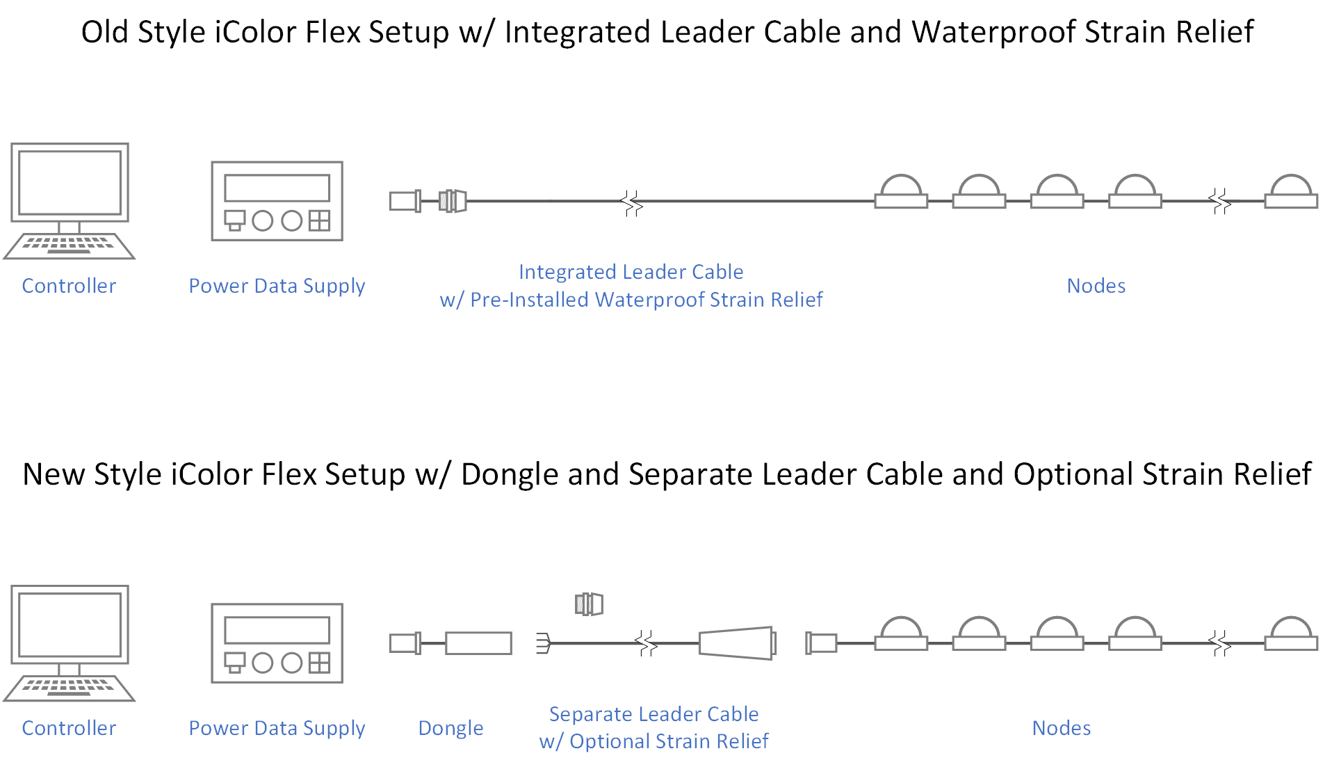
The two different iColor Flex setups. These are distinguished by having an integrated leader cable or a separate dongle and leader cable.
In a typical iColor Flex setup, a controller connects to a power data supply over a DMX-512 or wired Ethernet network and the power data supply connects to the lights via a leader cable. The power data supply injects DC power into the string of lights and translates the DMX-512 or Ethernet packets from the controller into the proprietary packet format used by the nodes.
In early versions of the lights, the leader cable was directly connected to the first node in the string and was typically twenty feet long. In the later versions, the power supply connects to the lights using a dongle and a leader cable that connects to a short pigtail from the first node in the string. The change was made to support non-outdoor power supplies, to allow for a longer leader cable, and to allow the leader cable to be cut to shorter lengths in the field.
The Older Setup: Controller, Power Supply, and Lights
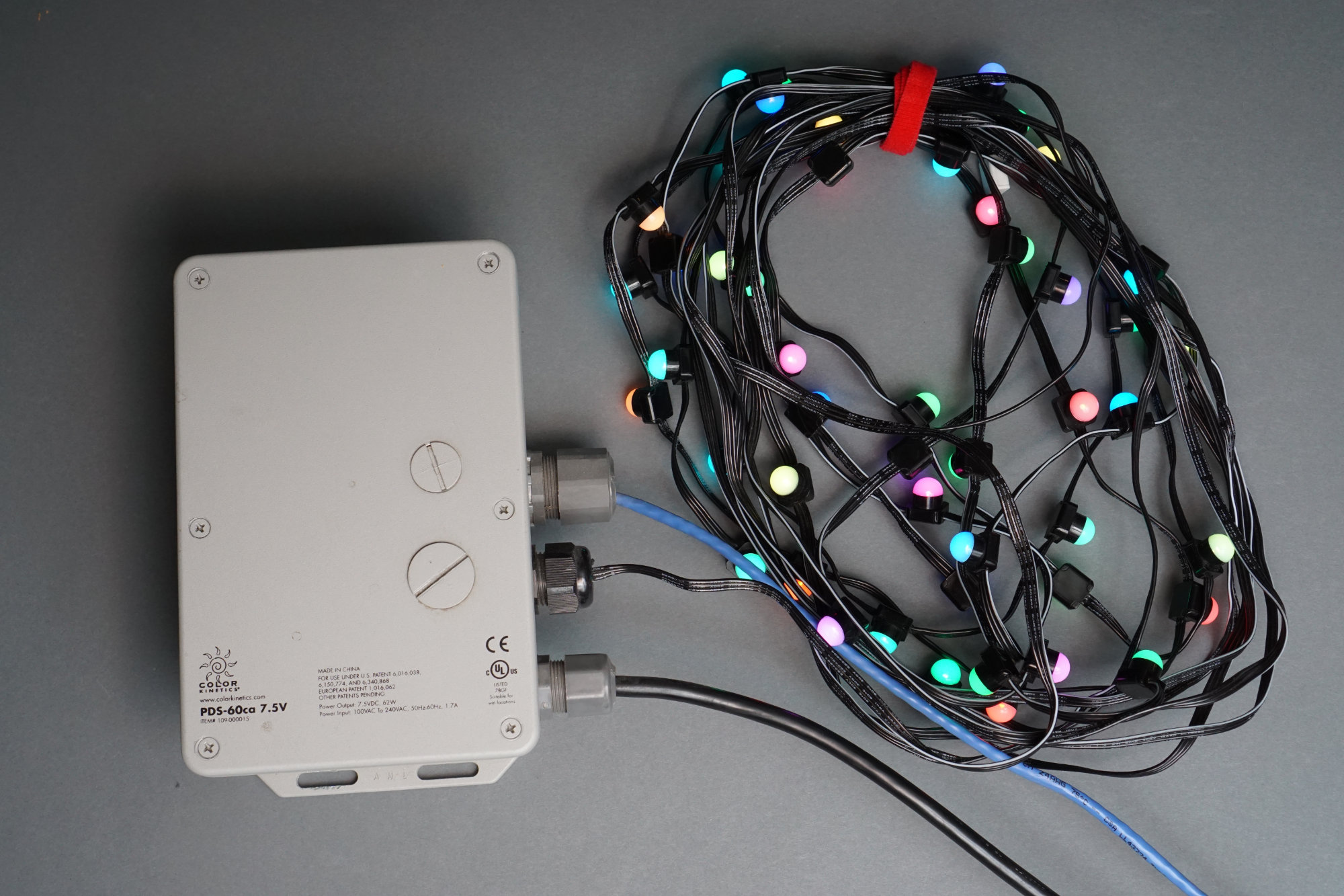
An iColor Flex SL setup. DMX data from a controller (not pictured) feeds into the power data supply then the power data supply connects to nodes using an integrated twenty foot leader cable.
On the older iColor Flex light strings, the lights connected directly to the power data supply via an integrated leader cable. The stock leader cable was twenty feet long but could be ordered shorter for custom products. The leader cable has a four-pin AMP connector that plugs directly into the power data supply. The AMP connector is very similar to the Molex connectors used on PC power supplies but is not the same and the two are not interchangeable.
A string of lights with a permanently attached twenty foot leader cable connected directly to a first generation outdoor rated power data supply. The four-pin power data connector is not removable so the waterproof cable bushing comes preinstalled on the leader cable.
The only power supplies available at the time were versions designed for outdoor use. Since the four-pin AMP connector on the leader cable could not be removed and re-installed in the field, the leader cable came with a waterproof strain relief preinstalled. The end user would mount the power data supply and lights, feed the end of the leader cable into the power data supply, mount the strain relief on the power-data supply, then plug in the 4-pin amp connector. Any excess cable would have to be bundled up, hidden, and stored near the supply or lights.
The Newer Setup: Controller, Power Supply, Dongle, Cable, and Lights
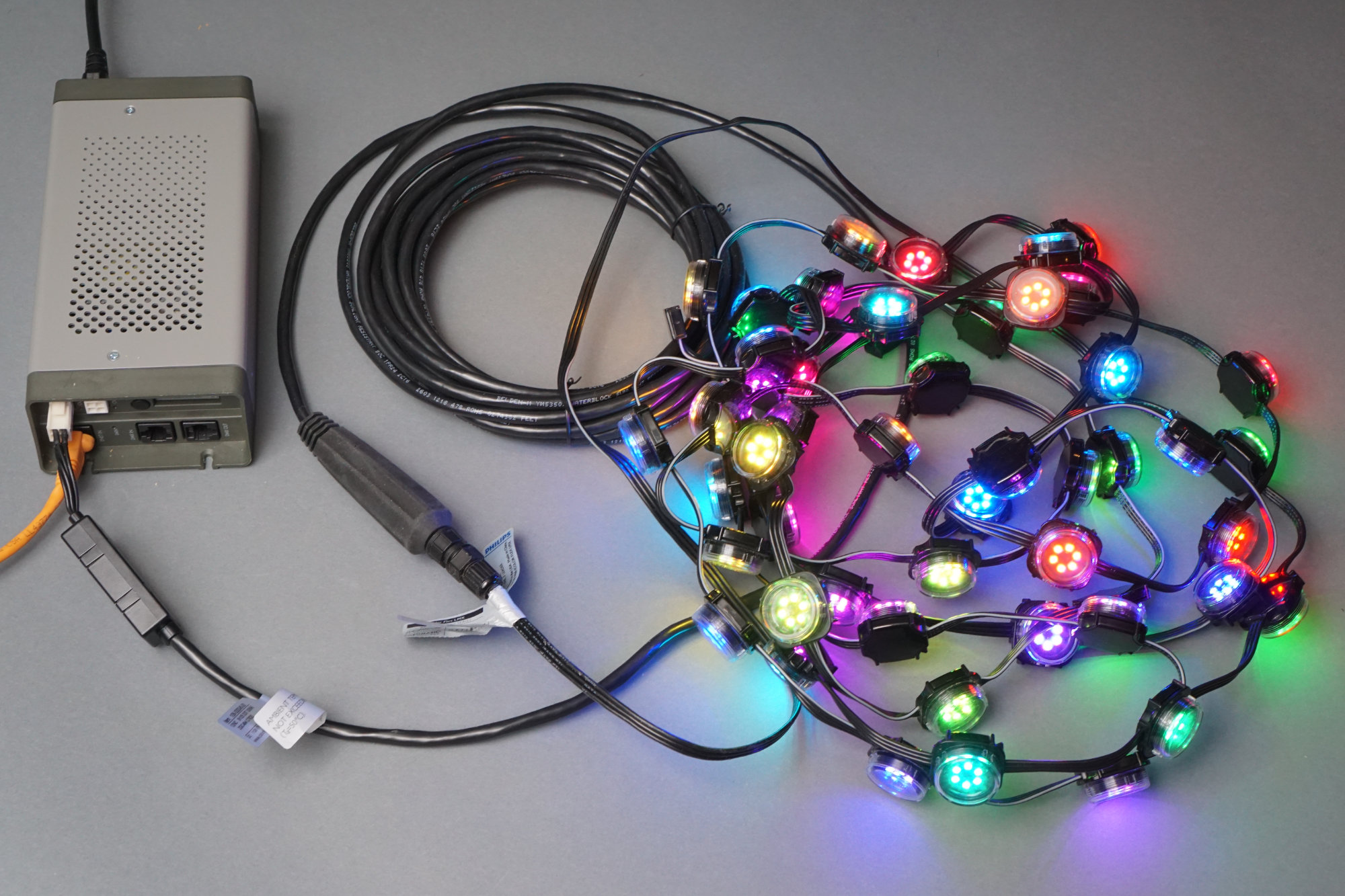
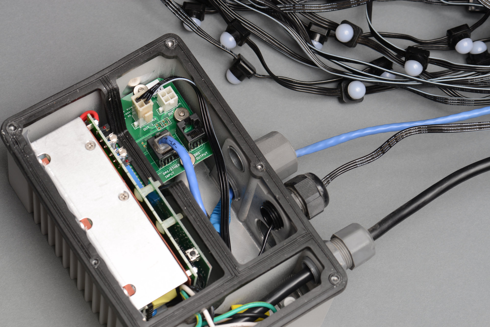
A complete iColor Flex LMX setup minus the controller. Ethernet data feeds into the power data supply. The power data supply is then connected to the nodes using a dongle and leader cable.
On the newer iColor Flex light strings, the lights connect to the power data supply via a dongle and detachable leader cable. The dongle plugs into the power supply, one end of the leader cable screws into a terminal block inside the dongle, and the other end of the dongle connects to a short pigtail from the first node in the string using three-pin Amphenol LTW circular connectors.
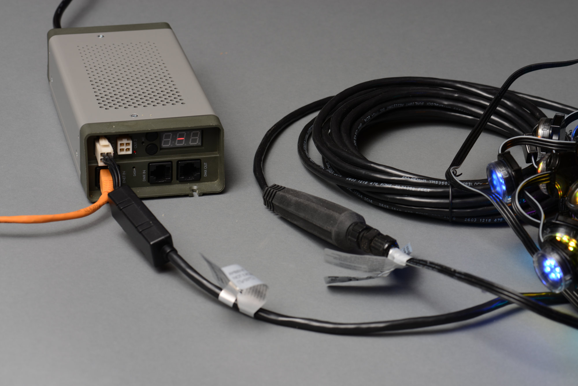
A newer indoor supply with a dongle, leader cable, and a few iColor Flex LMX nodes.
This change has several advantages. First, the user can order a stock leader cable, remove the dongle, shorten the leader cable, and then reconnect the dongle. This allows custom leader cable lengths to be cut in the field. Second, leader cables could be made longer while maintaining their signal integrity. Third, the installation of a waterproof strain relief could be performed in the field: detach the dongle, thread the strain relief on to the leader cable, then re-attach the dongle. If the installation is indoors, the use of the waterproof strain relief can be skipped. If the installation is outdoors, the dongle is small enough to fit two of them inside the outdoor power data supplies.
Goals for Our Reverse Engineering
Our goal is to figure out the pin out of each connector and the protocol used at each point between the power supply and first node on the string. This includes at the four-pin AMP connector on the power data supply, the screw terminal block inside the dongle, and at the three-pin Amphenol LTW circular connector at the lights. Let’s start by looking for any publicly available information about the power supplies, protocol, and lights.
What Public Information Is Available?
A good reverse engineering effort starts with surveying what information is publicly available. In the case of the iColor Flex LED strings, there’s a data sheet and a patent.
Data Sheet
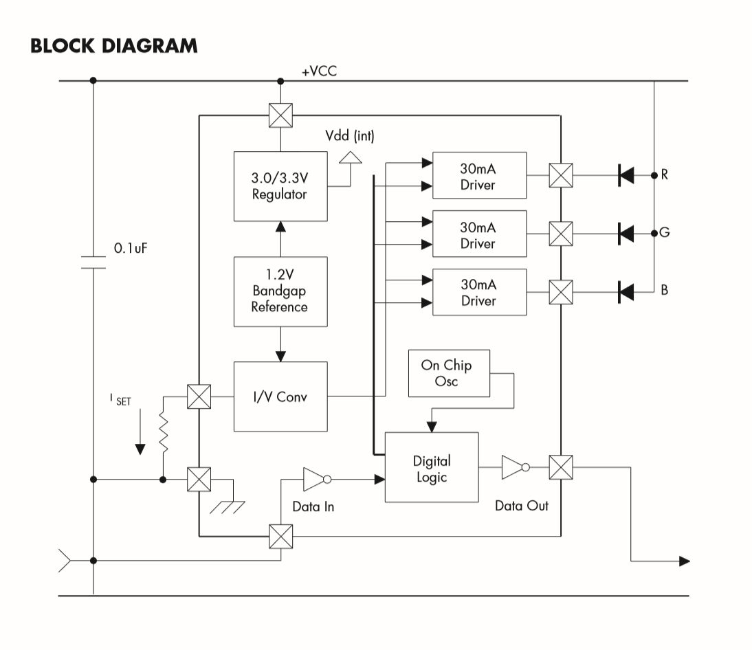
The block diagram from the Chromasic data sheet.
Color Kinetics has a mostly useless data sheet on their Chromasic chip posted on their website. The block diagram excerpted above is interesting just to see what is inside the chip. The most important information here is that the resolution of the chip and most likely the protocol is “12 bit PWM” with “64 billion additive RGB colors.” This implies we’re looking for 3 words of 12 bits in the protocol.
Patents
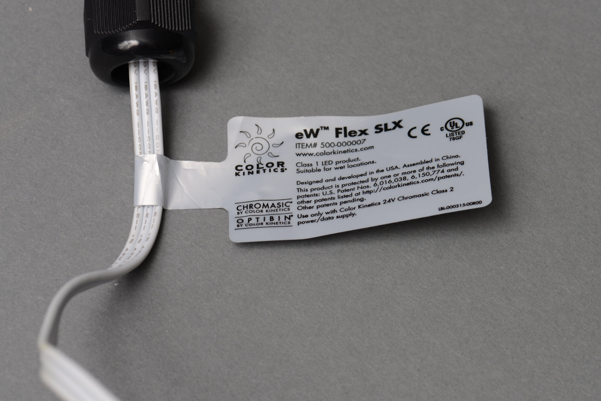
A tag listing two of Color Kinetics patents. These patents are both expired and the link is now dead too.
Color Kinetics likes patents and were quite litigious in their early days. The lawsuits slowed down after their acquisition by Philips and many of their early patents have expired or are expiring soon. But patents aren’t just for litigation–patents are supposed to describe inventions such that a person having ordinary skill in the art can reproduce those inventions, right?
Two patent numbers are listed on the tags on each string. These are not the patents we’re interested in though. These are patents on using PWM to dim LEDs and mix colors and have both expired. The patent we’re interested in is US Patent 7,598,684, Methods and apparatus for controlling devices in a networked lighting system. This patent covers “a plurality of LED-based lighting systems are arranged as computer controllable ‘light strings.'” This patent doesn’t expire until August 8, 2021.
Encoding
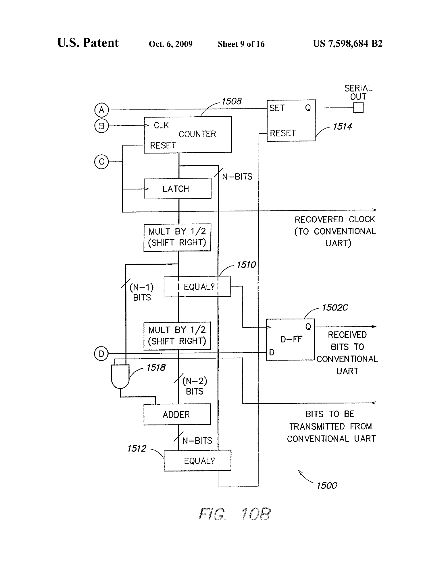
Figure 10B in the patent is used to describe encoding zeros and ones on the wire and recovering those values in the LED node.
The first of two big pieces of information in the patent is how bits are encoded. The patent includes a Figure 10B which shows a block diagram of the circuitry used to decode bits at the input of the node and re-encode new bits at the output of the node. The text that accompanies the figure describes a bit encoding scheme where the location of the falling edge between two rising edges determines the value of the bit. If the falling edge occurs before 1/2 the period, the bit is a zero. If the falling edge occurs after 1/2 the period, the bit is a one. The patent then goes on to describe a method using a counter to decode this encoding back to zeros and ones.
Self-Addressing

Figure 11 in the patent described the self-addressing scheme including detecting start codes and replacing “used” levels with start codes to forward to the next node.
The second of two big pieces of information in the patent is how the nodes are addressed. The text describing the addressing scheme is accompanied by a Figure 11. Basically the node looks for a start code then grabs the next three channels of data and uses those to set its levels. Rather than forward those three channels of data to the next node, it replaces those three channels of data with three start codes. The next node in the string will now see four start codes then grab three levels of data replacing the grabbed data with additional start codes. This continues until the last node on the string.
Power Supply and Power Supply Connector Pin Out
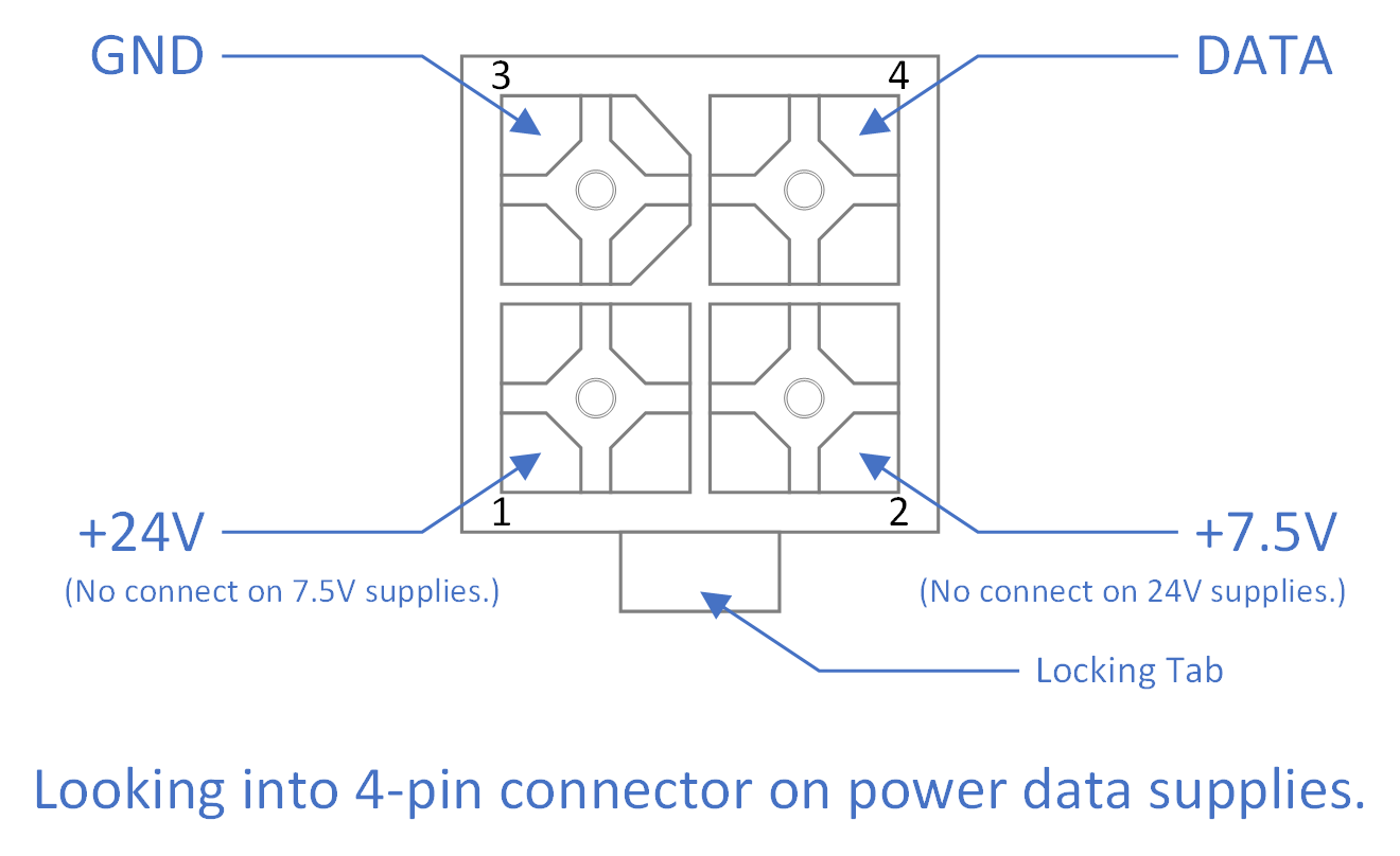
7.5 V and 24 V power data supply 4-pin power/data connector pin out.
The next step in reverse engineering the protocol was to figure out the pin out of the four-pin connectors on the power supplies. The string lights only use three of the four pins on the four-pin plug. I used a DMM and measured across the various permutations of these three pins on a 24 V power supply until I found a pair of pins that matched the supply voltage. The third pin should then be the data pin. I measured the voltage and it was about 2.35 V which is well within the electrical limits of my scope and its probes.

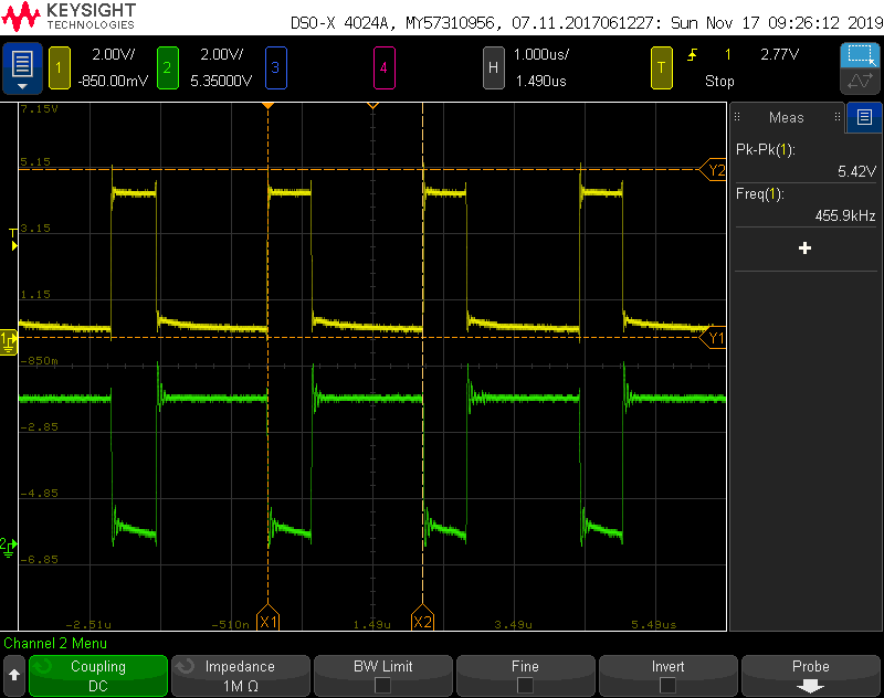
The data output at the output of the power data supply.
The next step was to use an oscilloscope to observe the signal on the third pin. The signal had a low voltage of 0 V, a high voltage of 5 V, and a frequency of 454.5 kHz measured rising edge to rising edge. The observed square wave signal alternated between two distinct duty cycles. The first duty cycle was high for 0.6 us then low for 1.6 us. The second duty cycle was high for 1.6 us then low for 0.6 us. These findings were good news because both the frequency and the waveforms are similar to those described in the patent.
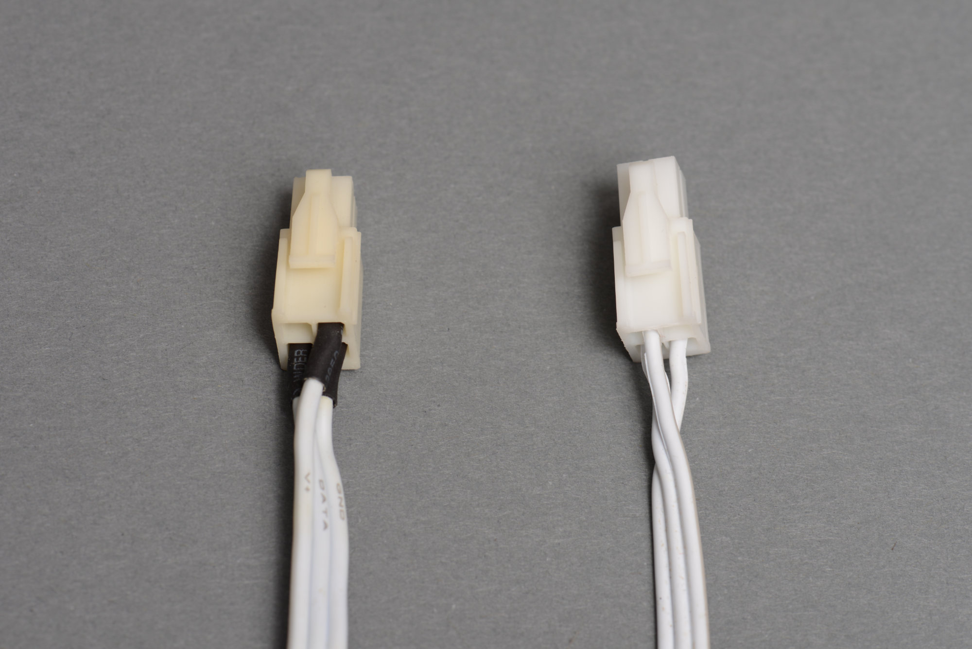
On the left is a string of lights requiring 24 V. On the right is a string of lights requiring 7.5 V. Notice the pin out differences between the two.
The next catch was that the 7.5 V string lights and the 24 V string lights use a different set of three of the four pins. A bit more probing with the DMM discovered that both strings of lights used the same data and ground pin but the 7.5 V lights used a different third pin than the 24 V lights. I probed the 7.5 V power supply and quickly discovered that the two power supplies place their output voltages on different pins presumably to stop end users from accidentally applying 24 V to a 7.5 V light string.
The last step was to discover the manufacturer and part number for the connectors used on the power supply and the string of lights. They looked like Molex connectors but observing the connectors under a microscope revealed an AMP logo and pin numbers embossed in the plastic. I used a set of calipers to take some measurements of the connectors and browsed the Digi-Key and TE Connectivity websites until I found the matching connectors. The connectors and their part numbers for making your own power supplies, cables, and adapters are:
| Description | Manufacturer | Part # |
|---|---|---|
| Board-mount connector | TE Connectivity | 1-770174-0 |
| Right-angle board-mount connector | TE Connectivity | 1-770968-0 |
| Free-hanging plug | TE Connectivity | 172167-1 |
| Crimp contacts for 18-22 AWG wire | TE Connectivity | 794831-1 |
I couldn’t justify a ratcheting crimping tool to crimp wires on to the contacts so I’m using a Molex #63811-1000 non-ratcheting hand crimp tool to crimp the contacts onto wires when making my own cables.
The Dongle
The dongle doesn’t look very complicated.
The next step was to figure out what the dongle and the huge lump at the end of the leader cable do. The dongle has a three-inch pigtail terminated in an AMP four-pin connector that plugs into a power data supply. The other end of the dongle has four-position screw terminal block that connects to the leader cable. The user can remove the cable from the dongle, cut it to length, install a waterproof bushing for outdoor use, then reconnect the cable to the dongle.
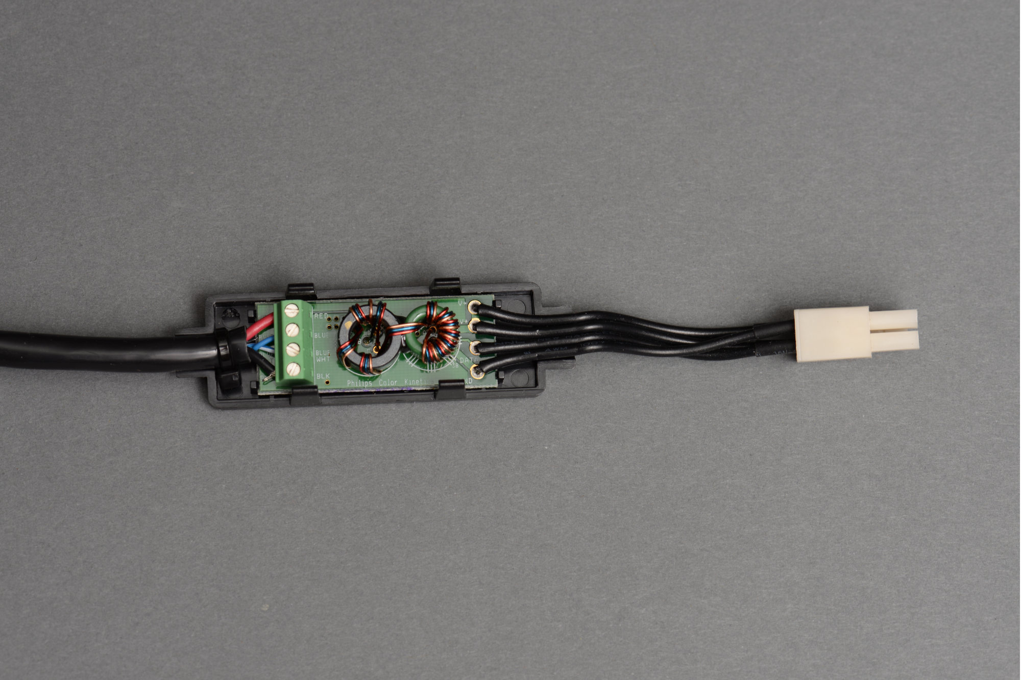
Taking a dongle apart, it looks simple enough. V+, V+, GND, and DATA solder pads on the input side, a bunch of coils, and RED, BLUE, BLUE/WHITE, BLK labels on the screw terminals on the output side. The V+ and V+ solder pads on the input side have a trace connecting them together so that the dongle gets power regardless of whether it is attached to a 7.5 V or 24 V power data supply. Looking at the leader cable though, the four conductors are two different gauges. The red and black wires are heavier gauge then the blue and blue/white wires. Furthermore, the blue and blue/white wires are twisted together into a pair. Something more must be going on.
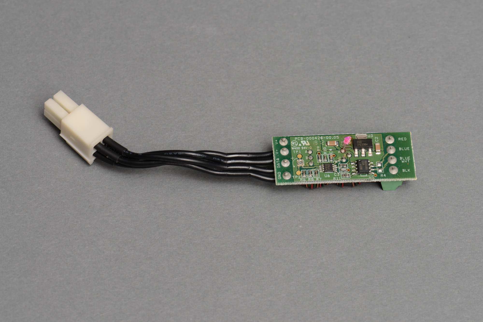
OMG. There’s a ton of stuff going on inside the dongle.
Indeed, removing the board completely from the plastic enclosure and looking at the back reveals quite a few chips and passives. There’s a what’s most likely a comparator, a small power supply, and most importantly for us, a MAX485 RS-485/RS-422 transceiver. While examining the circuit board traces around the MAX485, I made a few observations. First the MAX485’s receiver is hard-wired to be disabled. Second, the MAX485’s transmitter is hard-wired to be enabled. Lastly, the MAX485’s output is directly connected to the blue and blue/white screw terminals.
Differential data output at the output of the dongle.
My conclusion is that the dongle converts the single-ended signal from the power data supply into a differential signal to transmit through the leader cable and to the lights. Differential signalling allows the use of leader cables up to about 100 feet versus the old single-ended lights that had a maximum leader cable length of up to about 20 feet. Viewing the dongle’s data input and outputs on a scope confirms this is the case.
The screw terminal labeled RED is the DC voltage from the power supply. The BLUE terminal is the inverted data output. The BLUE/WHT terminal is the non-inverting data output. Finally, the BLACK terminal is ground.
The Other End of the Leader Cable
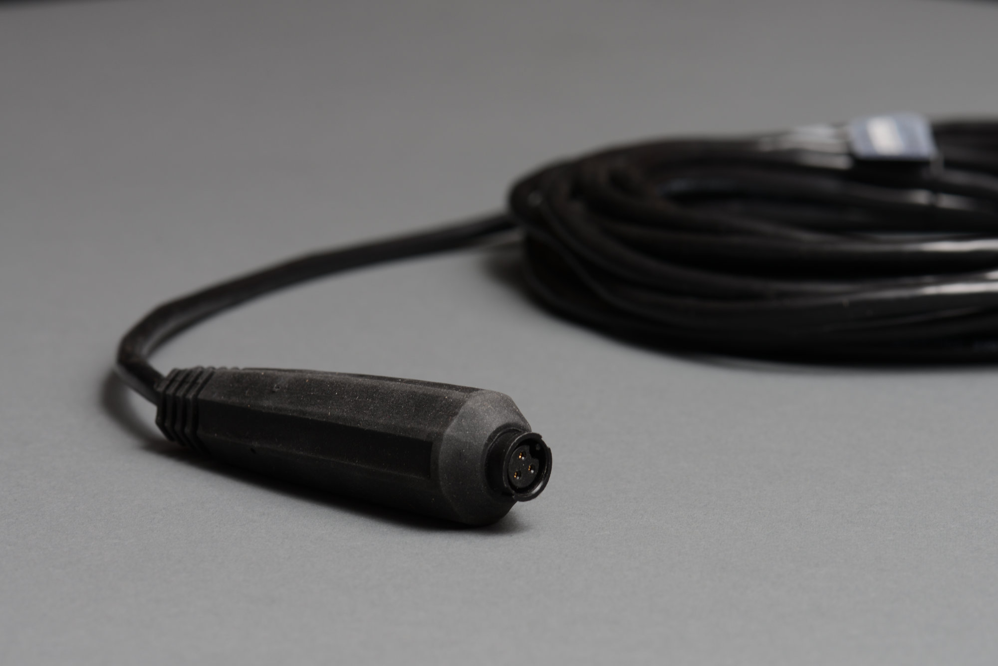
The lump in the far end of the leader cable that connects to the light strings.
The other end of the leader cable has a huge lump with an Amphenol LTW three-pin circular connector that connects to the light string. This end of the cable is pretty well sealed so I didn’t take it apart. This end of the cable converts the differential signal back into a single-ended signal to drive the lights.
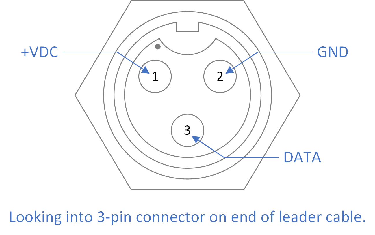
Leader cable pin out.
I used a DMM and scope to determine the pin out of the connector. The connectors on the light strings are stamped LTW. I used this fact along with a set of measurements to find the connector manufacturer and part numbers for making my own cables.
| Description | Manufacturer | Part # |
|---|---|---|
| Board-mount receptacle, sockets | Amphenol LTW | BD-03PMFS-LC7001 |
| Inline receptacle, sockets | Amphenol LTW | BD-03BMFA-LL7001 |
| Inline plug, pins | Amphenol LTW | BD-03BFMA-LL7001 |
Digging into the Protocol
Time to dig into the protocol and see how to control the lights. We already used a scope to derive the voltage levels and timing of the protocol. Now it was time to capture lots of data with varying light levels to derive how the levels are communicated to the lights. From the patent, we’re looking for a start code followed by light levels. From their marketing communications, we’re looking for RGB levels with 68 billion possible different colors. This translate to 36 bits or three words of 12 bits.
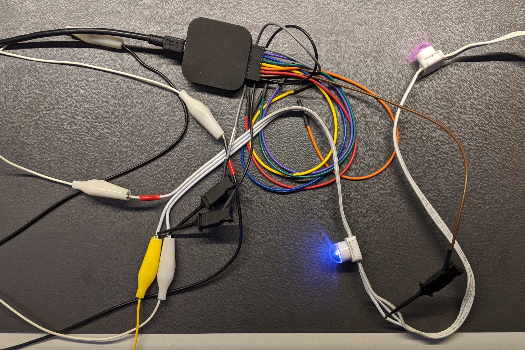
Using a small USB logic analyzer to capture data into and out of the the first node in the light string.
This step involved a lot of tedious work sending different color patterns to different numbers of nodes and observing the output of the power data supply with a small logic analyzer. I used two channels of the logic analyzer. The first channel was connected between the power data supply and the first node on the string of lights. The second channel was connected between the first and second node on the string of lights.
After performing a capture with the logic analyzer, I saved the captured data to a file then wrote some C code to parse the timing of the rising and falling edges into zeros and ones based on whether or not the falling edge occurred before (zero) or after (one) half the time between two successive rising edges. There were two possibilities here. I guessed correctly.
After many, many captures the protocol became apparent. Here’s a snip of a data capture between an older outdoor-rated power data supply and the first node with the first node set to red with a bit of blue and the second node set to yellow:
111111111111100000000
101111111111100000001000000000000000000010011000000000000000
101111111111100000001010100001111000000010000000000000000000
100000000000000000001000000000000000000010000000000000000000
100000000000000000001000000000000000000010000000000000000000
100000000000000000001000000000000000000010000000000000000000
100000000000000000001000000000000000000010000000000000000000
100000000000000000001000000000000000000010000000000000000000
100000000000000000001000000000000000000010000000000000000000
I noticed a start code of 13 ones followed by 8 zeros followed by data that varied based on the light levels. This pattern occurred at 25 ms interval which matched the update rate set in my controller software.
Immediately following this start code were 20 bit words. Each word began with a one, had 12 varying bits, then ended with 7 zero bits. From varying the levels and performing many captures I observed the light levels varied between 0 and 4094, were ordered red -> green -> blue, and were sent least-significant bit first. A light level of 4095 would be identical to a start code so the maximum light level is 4094 instead of 4095.
The data between the first node and second node was identical to the data between the power supply and the first node except the start code was now a 20 bit word and the RGB levels of the first node’s data had been replaced with start codes:
11111111111110000000
111111111111100000001111111111111000000011111111111110000000
101111111111100000001010100001111000000010000000000000000000
100000000000000000001000000000000000000010000000000000000000
100000000000000000001000000000000000000010000000000000000000
100000000000000000001000000000000000000010000000000000000000
100000000000000000001000000000000000000010000000000000000000
100000000000000000001000000000000000000010000000000000000000
100000000000000000001000000000000000000000000000000000000000
There were some additional wrinkles in the protocol. About six nodes of zero data are sent after the number of nodes configured in the software. These seem to be required to pump the last few nodes of data out to the end of the strings for some reason. With the newer power data supplies, the blue channel is sent as a 21 bit word instead of a 20 bit word. The newer power data supplies also send a start code followed by a few zero bits when the line is idle versus the older power data supplies that just send zero bits all the time.
The Protocol
Here’s my final observation of the protocol:
- Send zero bits when the line is idle. Optionally: send start codes followed by a small number of zero bits. When ready to send data, revert to sending zero bits for a few hundred bits.
- When node data is ready to send:
- Send the 21 bit start code ‘b1_111111111111_00000000
- Send the first node’s 20 bit red value ‘b1_rrrrrrrrrrrr_0000000
- Send the first node’s 20 bit green value ‘b1_gggggggggggg_0000000
- Send the first node’s 21 bit blue value ‘b1_bbbbbbbbbbbb_00000000
- Repeat steps B through D for the remaining nodes
- When node data is done being sent, send six nodes of zero level data:
- Send 20 bit red zero value ‘b1_000000000000_0000000
- Send 20 bit green zero value ‘b1_000000000000_0000000
- Send 21 bit blue zero value ‘b1_000000000000_00000000
- Repeat steps A through C six times
The above protocol seems to work with the string lights that I have.
Compared to WS2812b / Neopixels
The WS2812b / Neopixel LEDs, tapes, and strings were developed about a decade after the iColor Flex string lights. It might be worth comparing and contrasting the Chromasic protocol to the WS2812b protocol.
First, the similarities. Sending a zero and a one is similar between the two protocols. A zero is a pulse with a short high time and a long low time. A one is a pulse with a long high time and short low time.
Now the differences:
| Item | WS2812b | Chromasic | |
|---|---|---|---|
| Baud Rate | 800 kHz | 454.4 kHz | |
| Bits Per Pixel | 24 | 36 | |
| Idle Pattern | Hold data line low | Send zeros | |
| Addressing Mode | Reset to address first node; used data is “swallowed” by the node and not sent to downstream nodes. | Send start code to address first node; consumed data is replaced by start codes sent to downstream nodes. |
Overall, the WS2812b protocol seems easier to implement on both microcontrollers and FPGAs mostly because you do not have to continuously send an idle pattern with the WS2812b LEDs.
Gamma Correction
Eight-bit DMX values from 0 to 255 map non-linearly to 12-bit values from 0 to 4094. This mapping is performed by the power data supply. I have not determined the exact mapping due to the time consuming nature of sending levels, capturing data with a logic analyzer, decoding it with my C code, then parsing through text files of zeros and ones. This would need to be done 254 more times to map all 256 DMX levels to their 12-bit values. I may build another FPGA in the future to help decode and determine the mapping used by the power data supplies.
Using an FPGA to Implement the Protocol
Hardware Interface
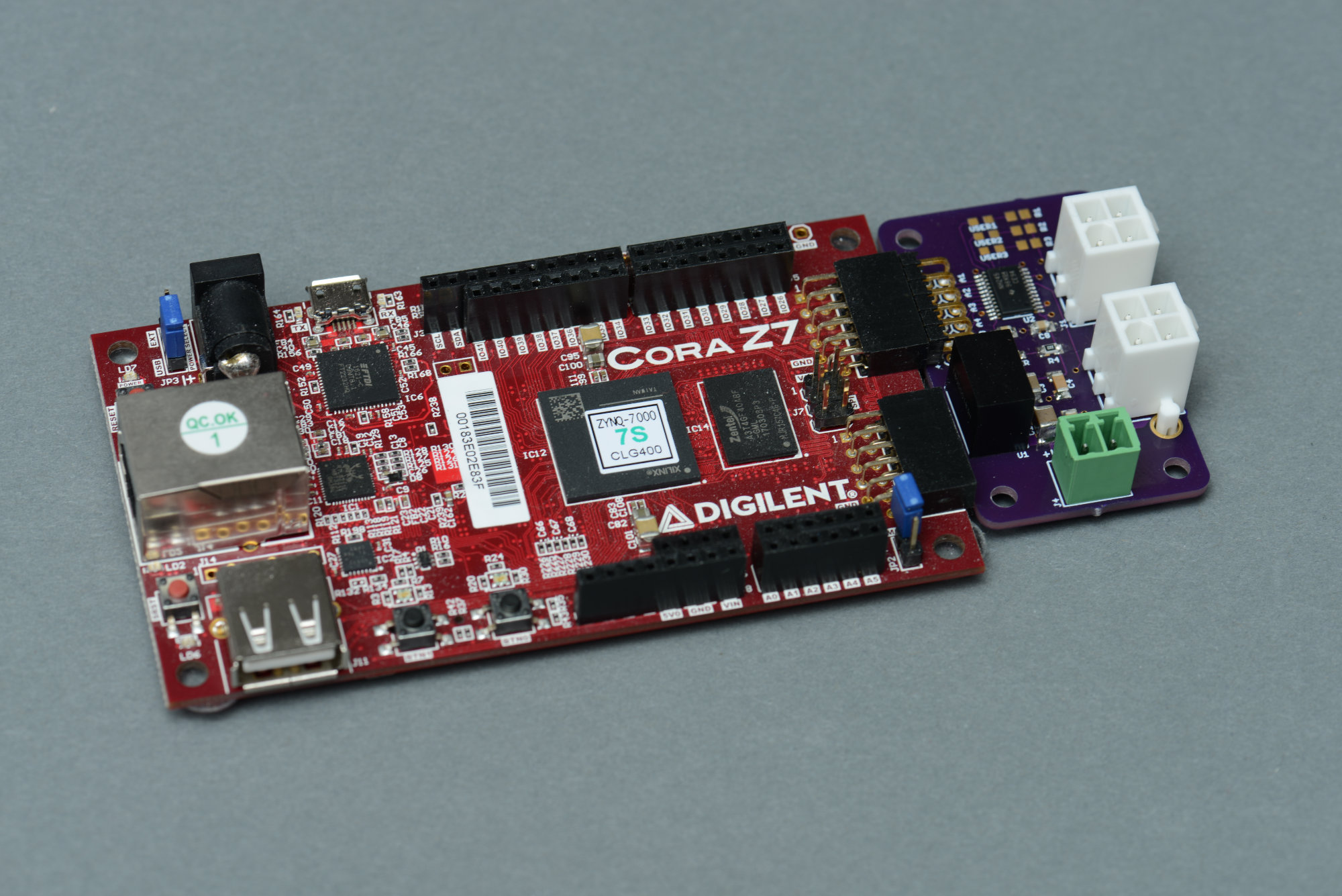
Digilent Cora Z7 FPGA board with a custom PMOD board to interface the FPGA to the iColor Flex strings.
The final step was to try my own implementation of the protocol against some of the iColor Flex light strings I own. I decided to use a Digilent Cora Z7 FPGA board and to build my own PMOD interface board to connect to the light strings. The interface board passes a DC power supply voltage to the light strings and contains a 3.3 V to 5 V level translator IC to convert the FPGA’s 3.3 V output to a 5 V data output for the light strings. It has a pair of AMP four-pin connectors so that up to two light strings may be connected at once.
Verilog
The protocol is implemented in two Verilog RTL modules. Both modules run at 10 MHz. The first module generates an enable at the baud rate of 1/2.2e-6 bits per second and encodes zeros and ones into the data encoding used by the light strings.
module ckca_encode
(
    input    wire            clk,
    input    wire            rst,
    output    reg                baudEn,
    input    wire            txd,
    output    reg             dout
);

    reg [4:0] encodeCount;

    always @ (posedge clk)
    begin
        if (rst)
        begin
            baudEn <= 0;
            dout <= 1;
            encodeCount <= 0;
        end
        else
        begin
            baudEn <= (encodeCount == 20);

            if (encodeCount == 21)
            begin
                encodeCount <= 0;
                dout <= 1;
            end
            else
            begin
                encodeCount <= encodeCount + 1;
                if ((encodeCount == 5) && (txd == 0))
                begin
                    dout <= 0;
                end
                else if ((encodeCount == 15) && (txd == 1))
                begin
                    dout <= 0;
                end
            end
        end
    end

endmodule
The second module is a funky UART that can send either 20 or 21 bits based on a flag in the input data word. Input data words come from a FIFO connected to the FPGA’s AXI4-Lite bus and internal ARM CPU. Bit[12] of the data word is the 20/21 bit flag. Bits[11:0] of the data word are the data to transmit and are positioned within the 20/21 bits sent to the ckca_encode module. The bits are sent to the ckca_module at the baud rate using the enable generated by that module.
module ckca_uart
(
    input    wire            clk,                // system clock
    input    wire            rst,                // synchronous, active-high system reset
    input    wire            baudEn,                // enable at baud rate
    input    wire            avail,                // new data byte to transmit available
    input    wire    [12:0]    data,                // 20/21b flag + 12 data bits
    output    reg                ack,                // data byte moved to transmit hold register
    output    reg                txd                    // transmit data out
);

localparam TXIDLE = 0, TXBRK = 1, TXMAB = 2, TXDAT = 3;

reg  [1:0] txbusy;                                // transmit state
reg  [4:0] bitnum;                                // current tx bit number
reg  [4:0] txbits;                                // number of bits to transmit minus one
reg    [19:0] txdata;                                // tranmsit data hold register

always @ (posedge clk)
begin
    if (rst)
    begin
        ack <= 0;
        txd <= 0;
        txbusy <= 0;
        bitnum <= 0;
        txbits <= 0;
        txdata <= 0;
    end
    else
    begin
        ack <= 0;

        if (baudEn)
        begin
            case (txbusy)

                TXIDLE: begin
                    if (avail)
                    begin
                        ack <= 1;
                        txd <= 1;
                        txbusy <= TXDAT;
                        bitnum <= 0;
                        txbits <= data[12] ? 20 : 19;
                        txdata <= { 8'h00, data[11:0] };
                    end
                    else
                    begin
                        txd <= 0;
                        bitnum <= 0;
                        txbusy <= TXIDLE;
                    end
                end

                TXDAT: begin
                    if (bitnum >= txbits)
                    begin
                        if (avail)
                        begin
                            ack <= 1;
                            txd <= 1;
                            txbusy <= TXDAT;
                            bitnum <= 0;
                            txbits <= data[12] ? 20 : 19;
                            txdata <= { 8'h00, data[11:0] };
                        end
                        else
                        begin
                            txd <= 0;
                            bitnum <= 0;
                            txbusy <= TXIDLE;
                        end
                    end
                    else
                    begin
                        txd <= txdata[0];
                        txdata <= { 1'b0, txdata[19:1] };
                        bitnum <= bitnum + 1;
                    end
                end

            endcase
        end
    end
end

endmodule
These two modules are instantiated inside a wrapper along with a FIFO and AXI4-Lite interface and connected to the Zynq FPGA’s ARM core using Vivado’s IP integrator.
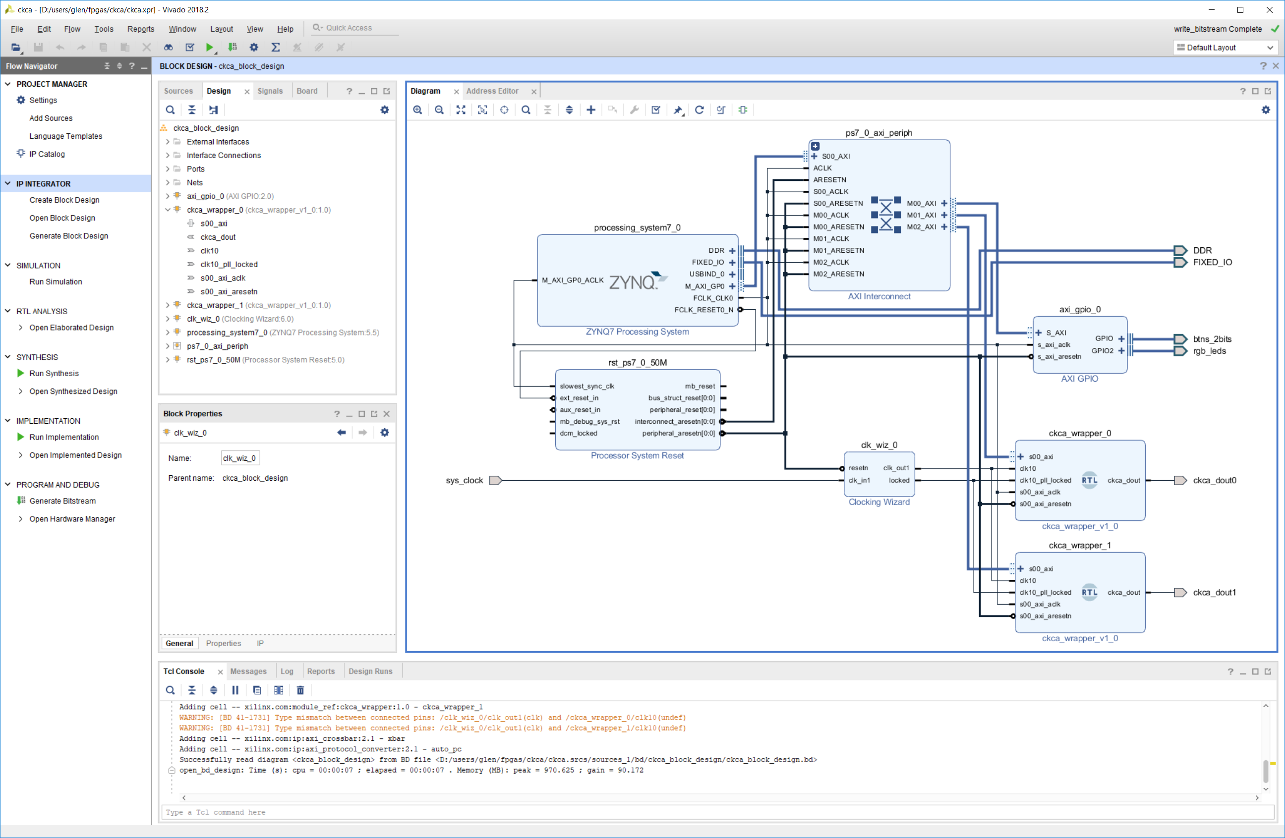
Two instances of my implementation of the protocol in the Vivado IP Integrator.
Software
Some quick software was written using the Xilinx SDK IDE to have 6 colors chase down a string of 10 nodes.
// includes
#include "platform.h"
#include "xgpio.h"
#include "xil_printf.h"
#include "xparameters.h"

// short cuts
#define CKCA0_TIMEBASE_VALUE_REG    (XPAR_CKCA_WRAPPER_0_BASEADDR + 0x10)
#define CKCA0_TIMEBASE_FLAG_REG     (XPAR_CKCA_WRAPPER_0_BASEADDR + 0x14)
#define CKCA0_FIFO_DATA_REG         (XPAR_CKCA_WRAPPER_0_BASEADDR + 0x18)

// color table
static const uint16_t colors[6][3] = {
    { 0x0FFE, 0x0000, 0x1000 }, // RED
    { 0x0FFE, 0x0FFE, 0x1000 }, // YELLOW
    { 0x0000, 0x0FFE, 0x1000 }, // GREEN
    { 0x0000, 0x0FFE, 0x1FFE }, // CYAN
    { 0x0000, 0x0000, 0x1FFE }, // BLUE
    { 0x0FFE, 0x0000, 0x1FFE }  // PURPLE
};

// main
int main()
{
    XGpio gpio;

    init_platform ();
    XGpio_Initialize(&gpio, 0);
    XGpio_SetDataDirection(&gpio, 2, 0x00000000); // set LED GPIO channel tristates to All Output
    XGpio_SetDataDirection(&gpio, 1, 0xFFFFFFFF); // set BTN GPIO channel tristates to All Input

    int timer = 0;
    int color = 0;
    int j, k;

    while (1) {
        if (Xil_In32 (CKCA0_TIMEBASE_FLAG_REG) & 0x1) {
            Xil_Out32 (CKCA0_TIMEBASE_FLAG_REG, 0x1);
            xil_printf (".");

            timer++;
            if (timer >= 20) {
                timer = 0;

                // send start code
                Xil_Out32 (CKCA0_FIFO_DATA_REG, 0x1FFF);

                // cycle through colors
                k = color;
                for (j = 0; j < 10; j++) {
                    Xil_Out32 (CKCA0_FIFO_DATA_REG, colors[k][0]);
                    Xil_Out32 (CKCA0_FIFO_DATA_REG, colors[k][1]);
                    Xil_Out32 (CKCA0_FIFO_DATA_REG, colors[k][2]);
                    if (++k > 5) {
                        k = 0;
                    }
                }

                // send six empty nodes of data to push data through last nodes
                for (j = 0; j < 6; j++) {
                    Xil_Out32 (CKCA0_FIFO_DATA_REG, 0x0000);
                    Xil_Out32 (CKCA0_FIFO_DATA_REG, 0x0000);
                    Xil_Out32 (CKCA0_FIFO_DATA_REG, 0x1000);
                }

                if (--color < 0) {
                    color = 5;
                }
            }
        }
    }

    return 0;
}
Trying It All Out
Here’s the result with a string of 10 iColor Flex MX nodes:
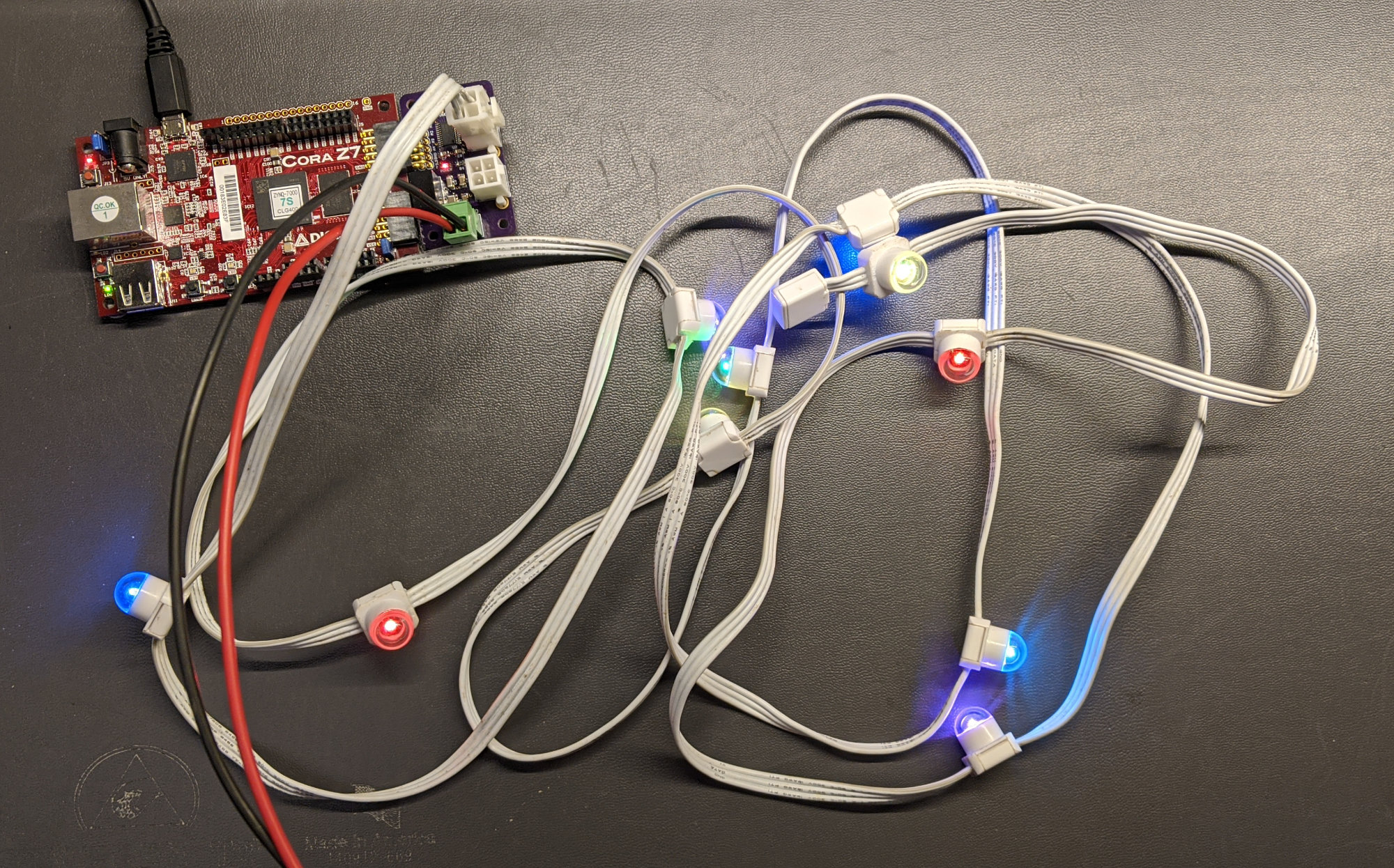
Here’s the result with a string of 6 iColor Flex MX gen 2 nodes:
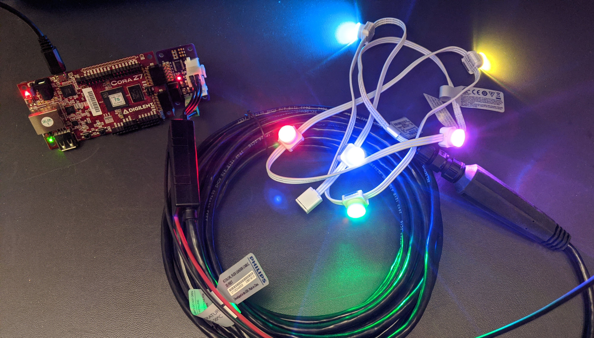
Here’s the result with a string of 10 iColor Flex LMX nodes:

Conclusion
I successfully reverse engineered the protocol used to control iColor Flex string lights based on their Chromasic chip and Chromasic protocol. After reverse engineering the protocol, I built a small circuit board and FPGA to implement the protocol and control a few different types of light strings.