
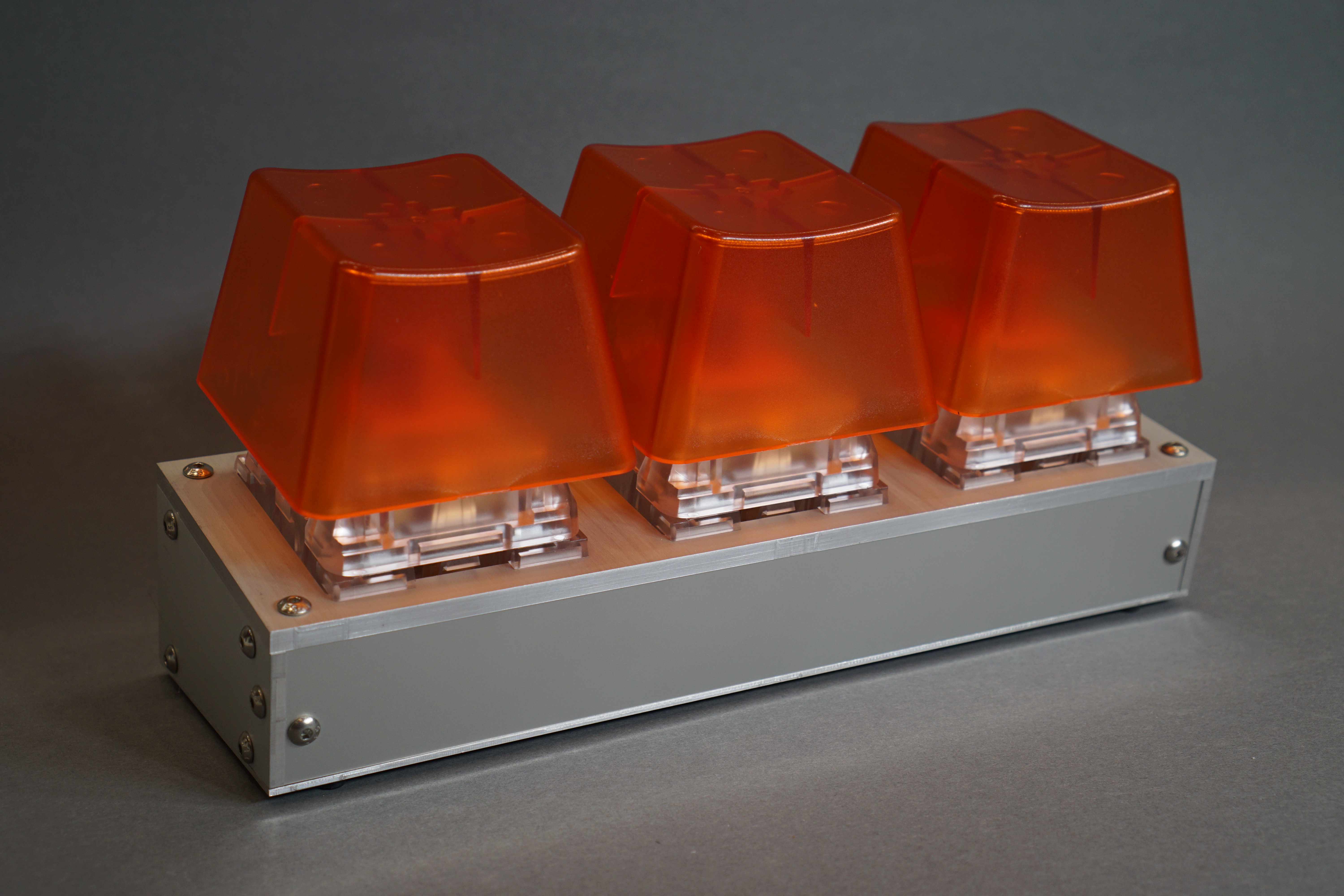
The completed giant USB three key mechanical keyboard.
After seeing this giant mechanical keyboard at Adafruit, I decided I had to build my own. Adafruit made theirs out of wood and used one of their Python-compatible microcontroller boards. I wanted a sloped top on my keyboard. I also wanted to check out what was new with Microchip’s USB device stack. I decided to build my keyboard out of aluminum and use a PIC18 microcontroller.
First Steps
The first steps were to acquire a few of the Novelkeys Big Switch Series keys and decide on a microcontroller. After perusing the Microchip PIC18 parametric search tool, I settled on the PIC18F14K50 in a 20 pin SOIC package. The PIC18F14K50 has a low-pin count USB development kit with an MPLAB X IDE USB HID example project. With the development kit and example project, it should be pretty easy to change the USB code to support my project. I ordered the keys, a few PIC18s, and the development kit.
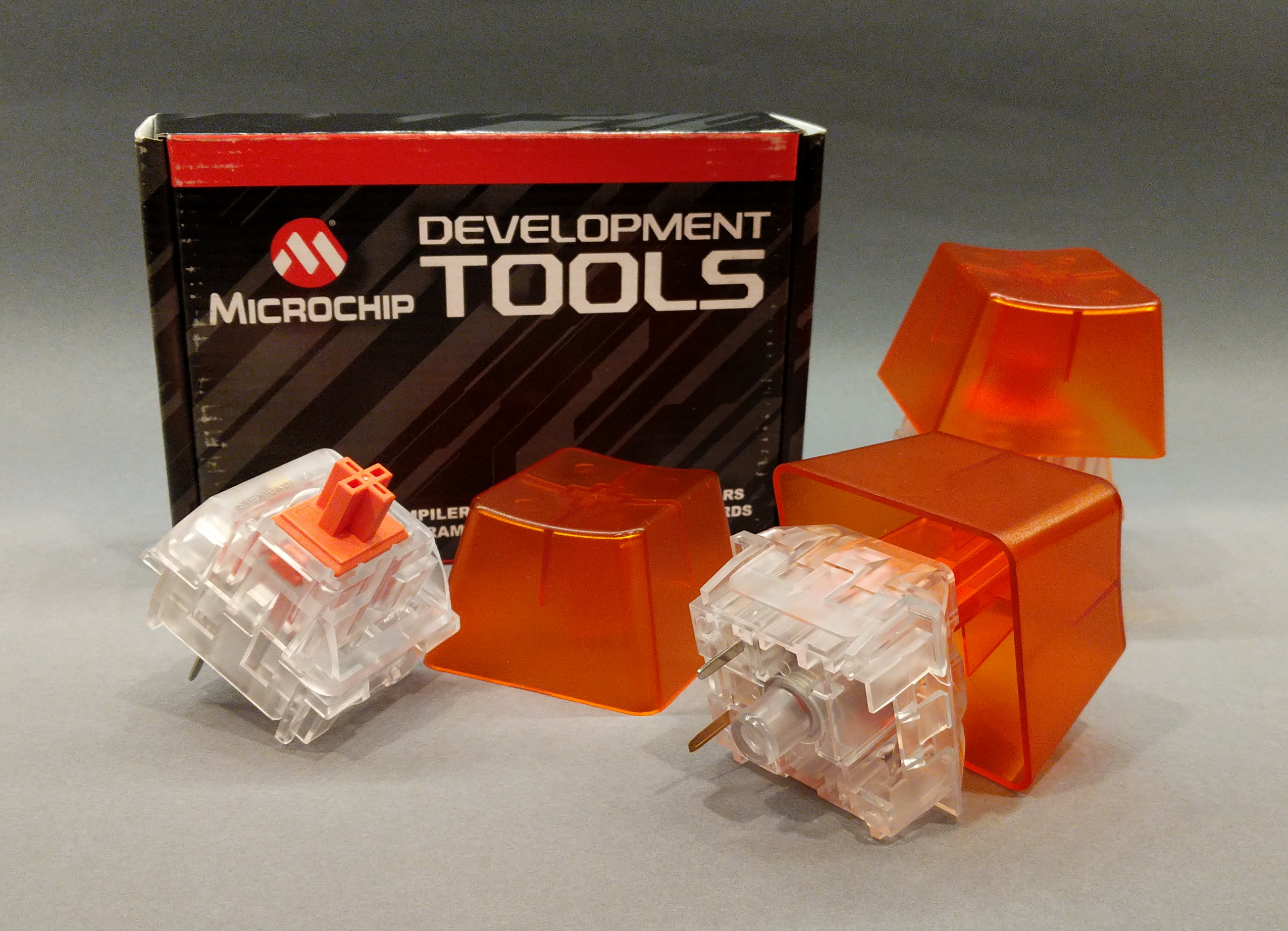
Three NovelKeys tactile orange big switch keys and the PIC18 low pin count USB development kit.
The Low Pin Count USB Development Kit
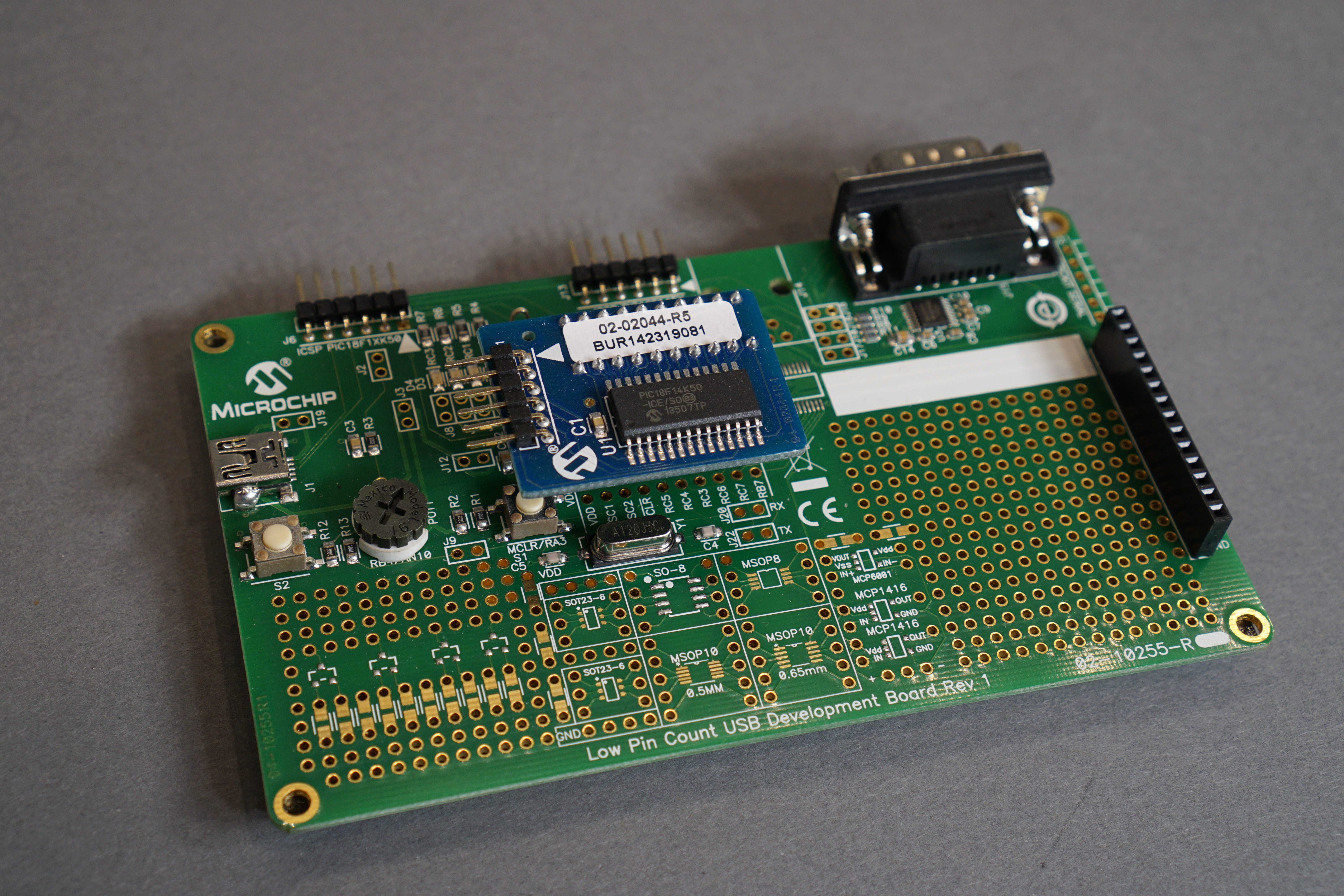
The Microchip Low Pin Count USB Development Kit. The blue board in the center has a special version of the PIC18F14K50 that bonds out the USB D+/D- pins separately from the in-circuit programming PGD/PGC pins.
The PIC18F14K50’s USB D+ and D- signals normally share the same pins as the in-circuit programming PGD and PGC pins. This makes programming or debugging the PIC18F14K50 while it’s attached to USB impossible! Fortunately, the USB development kit contains a special version of the PIC18F14K50 that bonds out the USB data signals and the in-circuit programming signals on separate pins. If I got in a jam, I could always use the development kit and the bond out board to debug my code!
The development kit comes with a PIC16F1459 in a DIP-20 package on the board. I removed this part and installed the PIC18F14K50 blue bond out board in its place. I connected my MPLAB REAL ICE debugger to the blue bond out board and connected the development kit to my PC using a USB cable.
Once the hardware was assembled, I downloaded and installed the Microchip Library for Applications. It took a bit of digging, but I eventually found the USB HID keyboard example in the C:\microchip\mla\v2017_03_06\apps\usb\device\hid_keyboard\firmware\low_pin_count_usb_development_kit_pic18f14k50.x project. I cleaned and rebuilt the project then programmed the part on the bond out board.
Windows 10 immediately found and enumerated a new USB HID device. When I pressed the small tactile switch on the USB development kit, the next letter from a continuous cycle of the alphabet appeared in my text editor. Also pressing caps lock on my normal keyboard toggled one of the LEDs on the development board. Happy that the PIC18F14K540 and the MLA USB HID keyboard example worked, I moved on to the mechanical design of the keyboard.
Measuring the Switches and Designing the Keyboard Enclosure
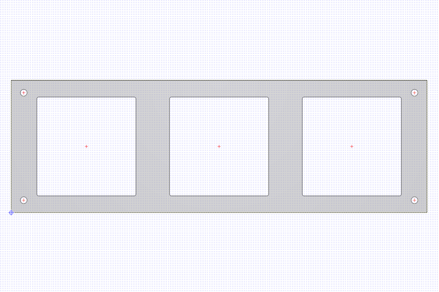
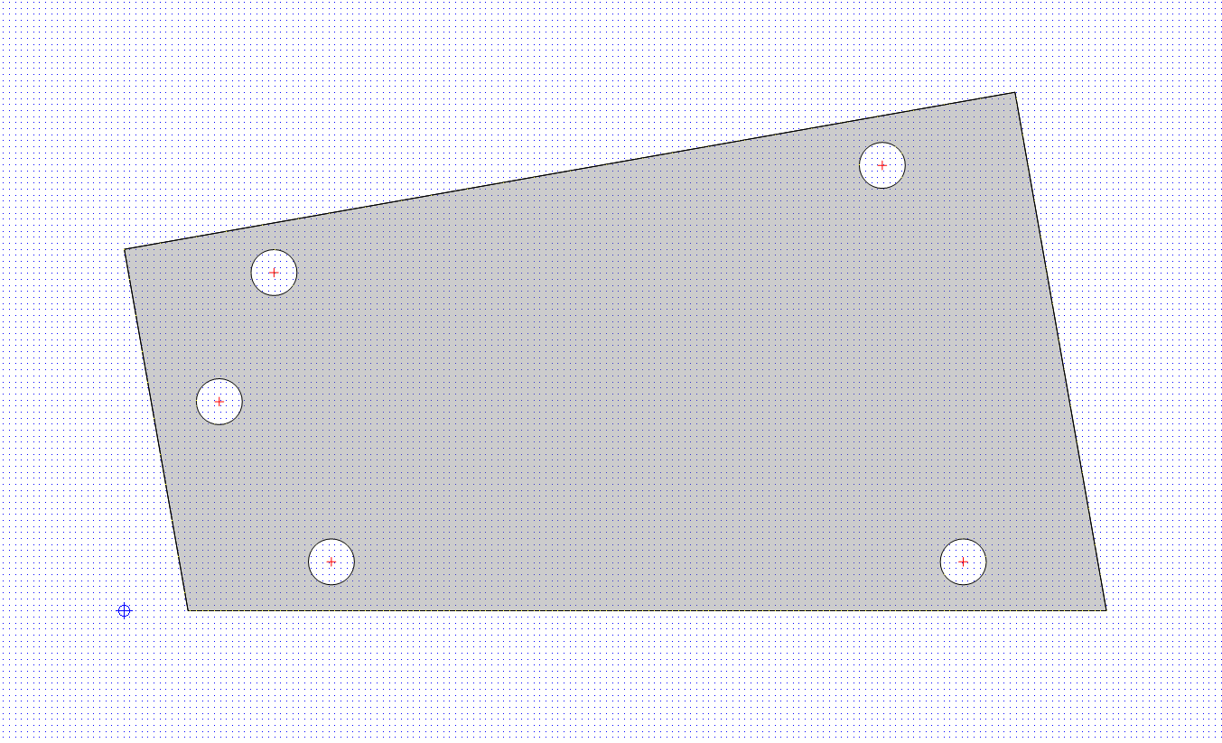
The top of the keyboard in Front Panel Express’s Front Panel Designer software.
The first step in designing the enclosure was to measure the switches. Using a pair of calipers, I determined that the switches needed to be mounted in 56mm square holes, the ideal panel thickness was about 5mm, and the keys needed to be mounted 75mm apart. I quickly sketched these up in Front Panel Express’s Front Panel Designer software.
Eventually I knew this top panel would need to be mounted to side panels. On my robot arm project, I had good luck using Servo City’s attachment blocks to secure aluminum panels at right angles to each other. I decided to use these to attach my top panel to the sides of the keyboard.
The attachment blocks are threaded to accept 6-32 screws. I added four 0.150″ holes to the corners of the top panel to loosely fit 6-32 screws. These were inset from the sides by 3mm, the thickness of the side panels, plus 0.160″, half the width of the attachment block. I then inset these from the front and rear edges by the same amount. This second distance didn’t matter but insetting them by the same amount resulted in a more symmetrical arrangement of the screws.
Planning for the Future
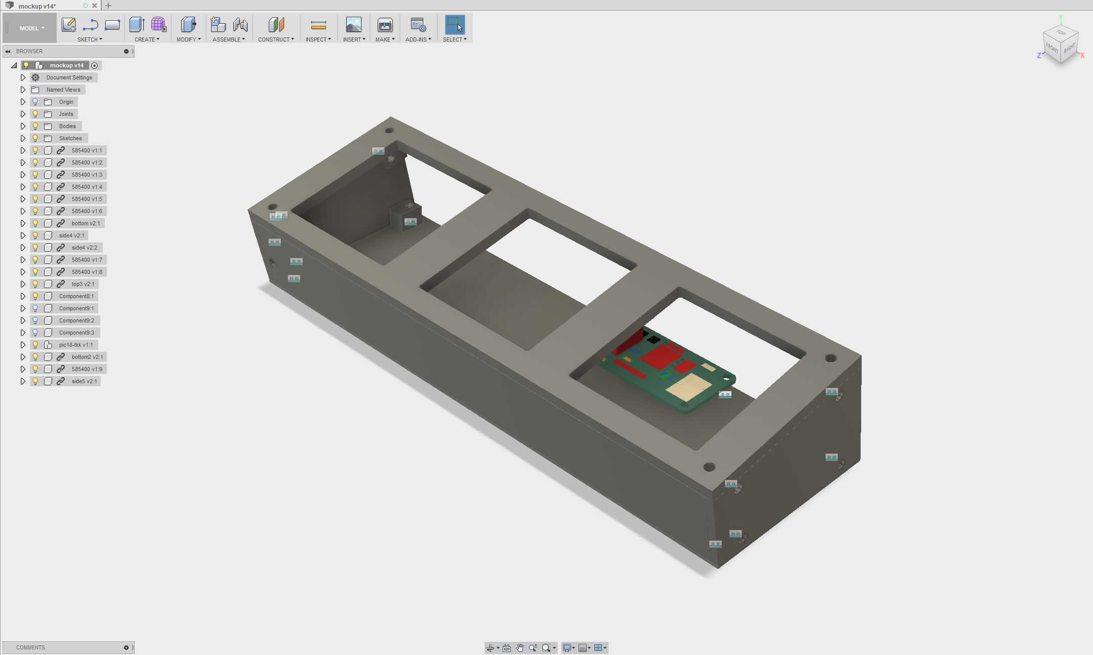
A mockup of the assembled enclosure in Autodesk Fusion 360.
I ordered the top panel from Front Panel Express then moved on to designing the rest of the enclosure in Fusion 360. I exported the top panel as a .DXF file from Front Panel Designer then imported it into Fusion 360 and extruded it to be 5mm thick. I added 3mm thick side panels, a 1.5mm thick front panel, and a 1.5mm thick bottom panel. I imported a 3D model of the attachment block then made liberal use of the rigid joint feature in Fusion 360 to assemble the enclosure. I didn’t order any panels at this point. I wanted to make sure everything worked before spending any more money.
The Top Arrives!
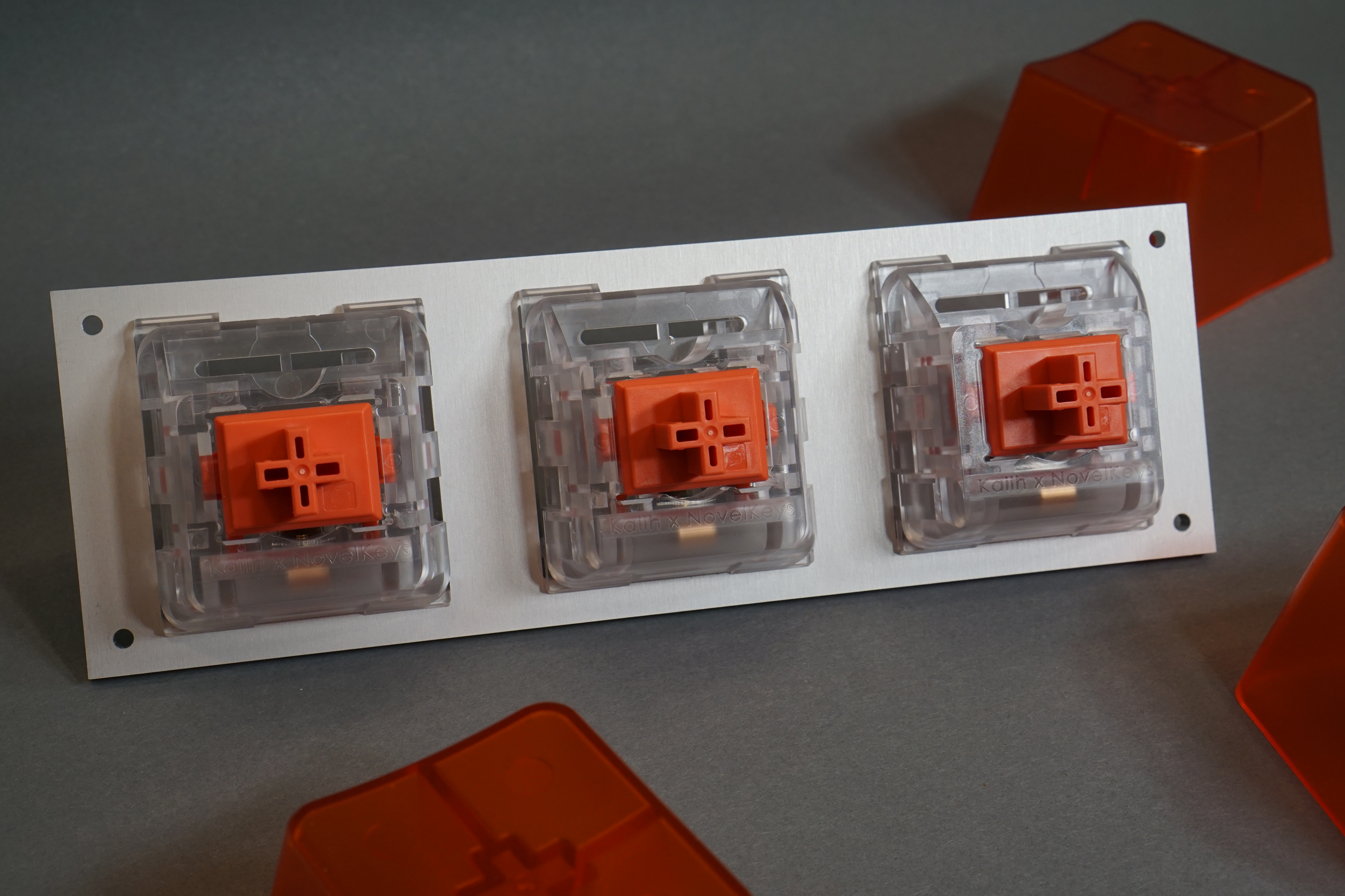
The top panel of the giant keyboard. Everything fits!
When the top panel arrived, I inserted the keys into the panel. They fit!
Designing the Board
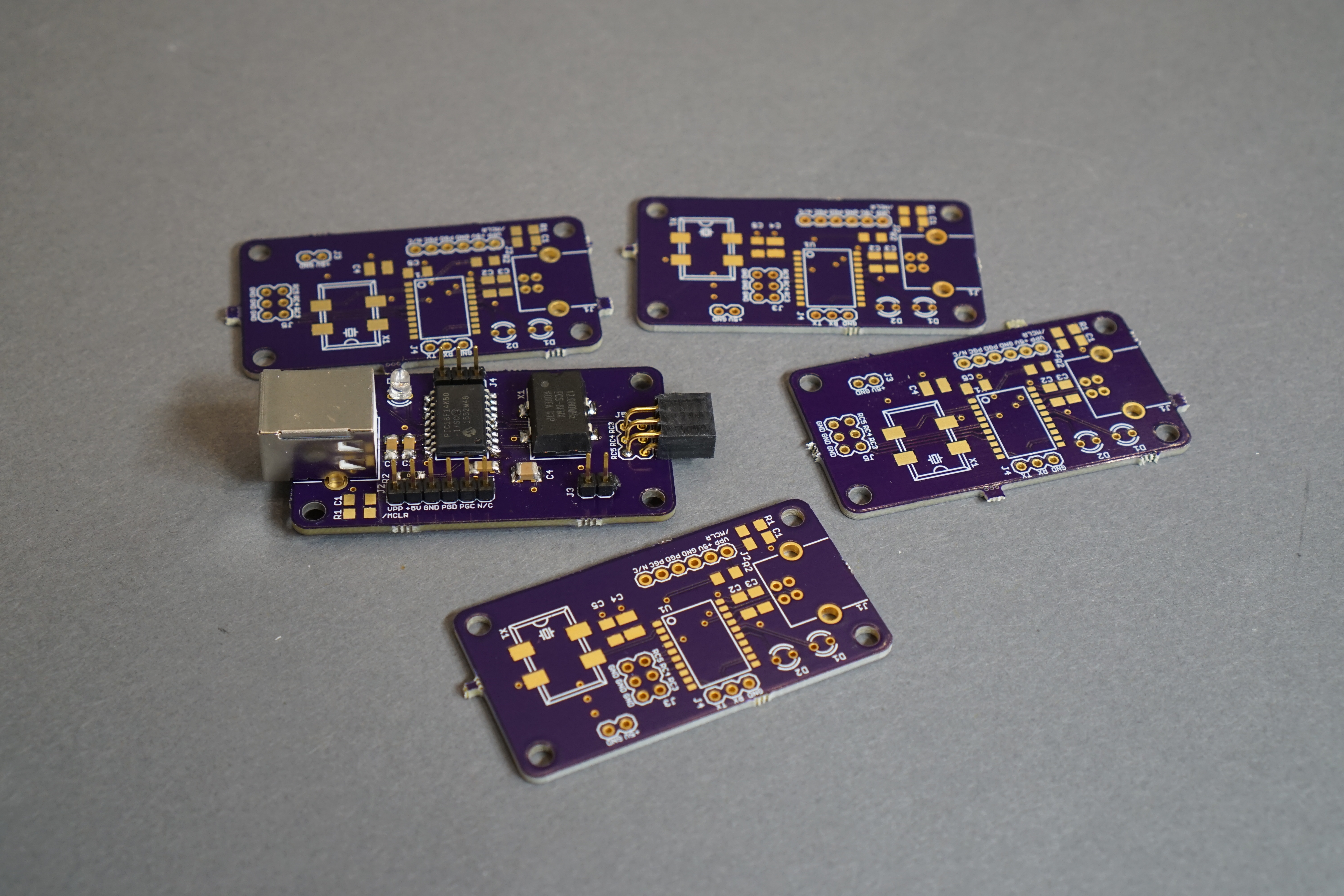
The USB interface for the giant three key keyboard uses these board and a PIC18F14K50 USB microcontroller. I made two versions of the board. One with a vertical connector for the switches and a 2nd with a horizontal connector for the switches.
Microchip makes implementing a USB device dead simple with the PIC18F14K50. Very minimal hardware is required. Essentially just a USB connector, the PIC18F14K50, a 12MHz clock source, and a few capacitors are required. To the basic required hardware, I added a few LEDs, an external power connector, a programming connector, a connector for the key switches, and a few pull up resistors. The D+/D- lines on the PIC18F14K50 are connected directly to the USB bus. The external power connector is only used when the board is disconnected from USB while programming the part.
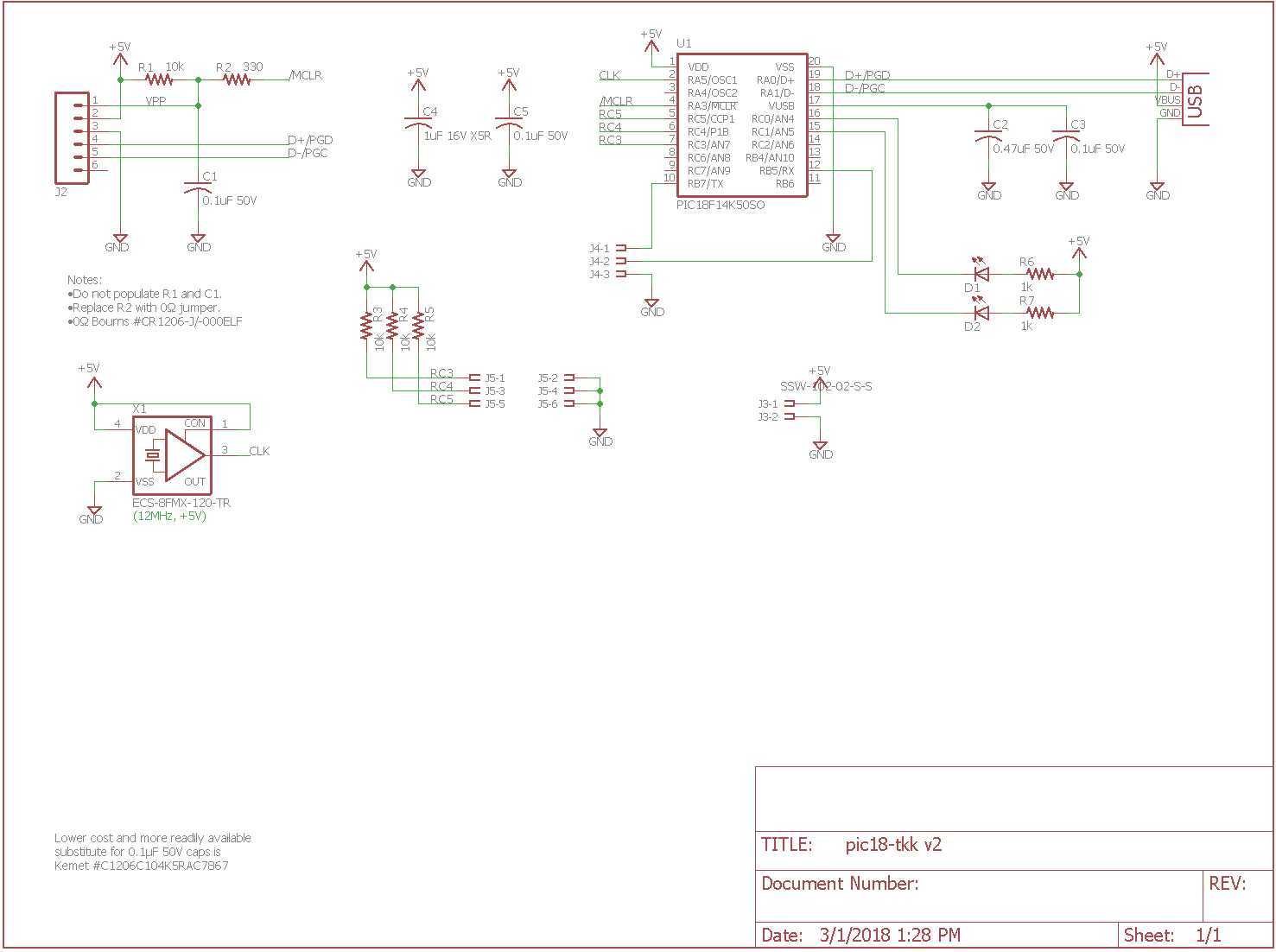
Schematic for the giant three key keyboard USB interface.
The Software
Ready to test the giant three key keyboard.
I made a copy of the USB HID keyboard example project. I added code to support three keys instead of one key and moved the LEDs and keys to the pins I was actually using on my board. I replaced the looping alphabet key generator with code to report keys ‘a’, ‘b’, or ‘c’ depending on which key was pressed. The code to build the keyboard input report is inside app_device_keyboard.c and looks something like this now:
int keynum = 0;
    if(BUTTON_IsPressed(BUTTON_USB_DEVICE_HID_KEYBOARD_KEY_0) == true)
    {
        inputReport.keys[keynum++] = 0x04; // the 'a' key
    }

    if(BUTTON_IsPressed(BUTTON_USB_DEVICE_HID_KEYBOARD_KEY_1) == true)
    {
        inputReport.keys[keynum++] = 0x05; // the 'b' key
    }

    if(BUTTON_IsPressed(BUTTON_USB_DEVICE_HID_KEYBOARD_KEY_2) == true)
    {
        inputReport.keys[keynum++] = 0x06; // the 'c' key
    }
I disconnected the board from USB, connected my programmer, and connected power. I programmed the part, disconnected power, and connected the board to my PC. I mashed a few keys. Success! Well, partially. These keys are extremely noisy and each time I pressed a key, I’d get from one to three characters instead of just one. Time to add some code to debounce the key switches.
The USB host sends a start of frame (SOF) packet once every millisecond. Inside usb_events.c is a task that executes every time an SOF packet is received. The example USB HID keyboard project uses this as a timebase to blink an LED indicating the USB status. I decided to use this as the timebase to debounce the keyswitches too. I added a call to a new BUTTON_UpdateStates function to the SOF event code. This function debounces the keyswitches.
The debounce algorithm runs once every 10ms and needs to see a key held down during two successive 10ms intervals to count the key as being pressed. In addition, it needs to see the key released on two successive 10ms intervals to count the key as being released. The debounce code just records the status of the key: pressed or not. A separate function called BUTTON_IsPressed returns whether the key is considered pressed or not.
Here’s the completed code:
void BUTTON_UpdateStates (void)
{
    // run this every 10-20ms to debounce and update button states for is pressed functions
    if (timer < 9) {
        timer++;
    } else {
        timer = 0;

        // button 1 debounce state machine
        switch (state1) {
            case 0:
                state1 = (S1_PORT == BUTTON_PRESSED) ? 1 : 0;
                break;
            case 1:
                state1 = (S1_PORT == BUTTON_PRESSED) ? 2 : 0;
                break;
            case 2:
                state1 = (S1_PORT == BUTTON_PRESSED) ? 2 : 3;
                break;
            case 3:
                state1 = (S1_PORT == BUTTON_PRESSED) ? 2 : 0;
                break;
        }

        // repeat something similar for buttons 2 and 3
}


bool BUTTON_IsPressed(BUTTON button)
{
    switch(button)
    {
        case BUTTON_S1:
            return ((state1 >= 2) ? true : false);

        // repeat something similar for keys 2 and 3

        case BUTTON_NONE:
            return false;
    }

    return false;
}
I programmed the part again, and, ta-da! Prefect. Exactly one character appeared for each press of the key. Also key repeat worked just like with a normal keyboard.
Finishing the Enclosure
The sides of the giant three key keyboard in Front Panel Designer. I used a .DXF exported from Fusion 360 as the shape of the panel then carefully transcribed the locations of the holes by hand between the two pieces of software.
With the software complete and successful, I decided it was time to finish designing and order the rest of the enclosure. I used Fusion 360 to project the side panels to a new sketch and exported the sketch as a .DXF. I created a new design in Front Panel Designer and selected the .DXF file as the shape of the panel. I couldn’t figure out a way to automatically export the holes from Fusion 360 into Front Panel Designer so I very carefully transcribed the location of each hole by hand between the two software packages. I then created the bottom and front panels for the enclosure. The bottom enclosure includes four 3.2mm holes for 4-40 screws and spacers to hold the USB interface board.
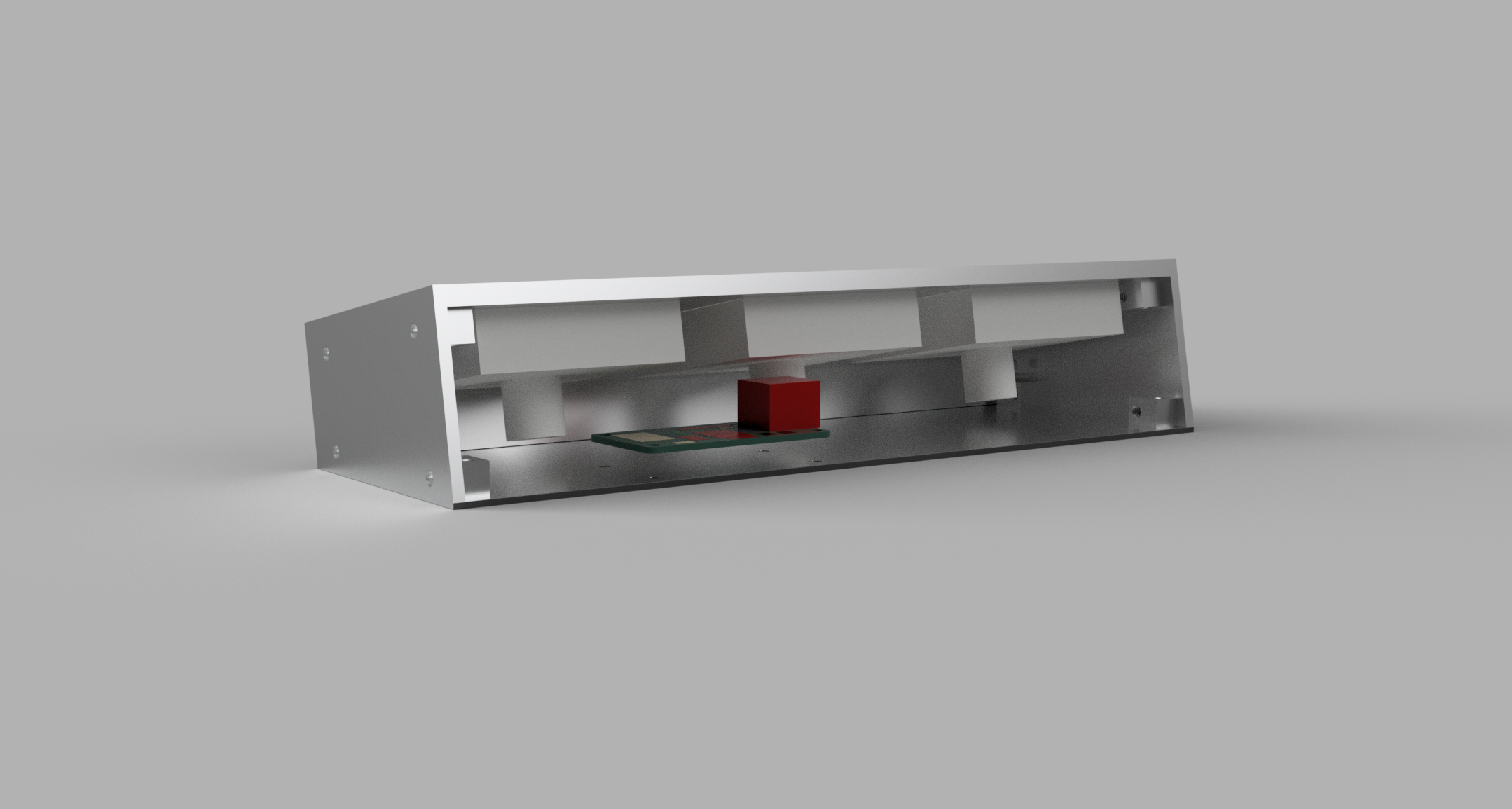
Final mockup of the giant three key keyboard in Fusion 360. I created a very simple model of the key switches to model the worst case volume and shape occupied by them.
The final step was to verify everything would fit together. I exported all the panels as .DXF files from Front Panel Designer. I used ecad.io to create a 3D MCAD model in STEP format from my circuit board design. I uploaded the .DXF files and STEP file into a new design in Fusion 360. I measured the rough dimensions of the key switches and created a component to represent the volume occupied by the key switches in Fusion 360. I then used the attachment block models and the joint function to assemble an almost complete mockup of the keyboard in Fusion 360. Once I was happy with the design, I ordered the panels.
Assembling the Enclosure
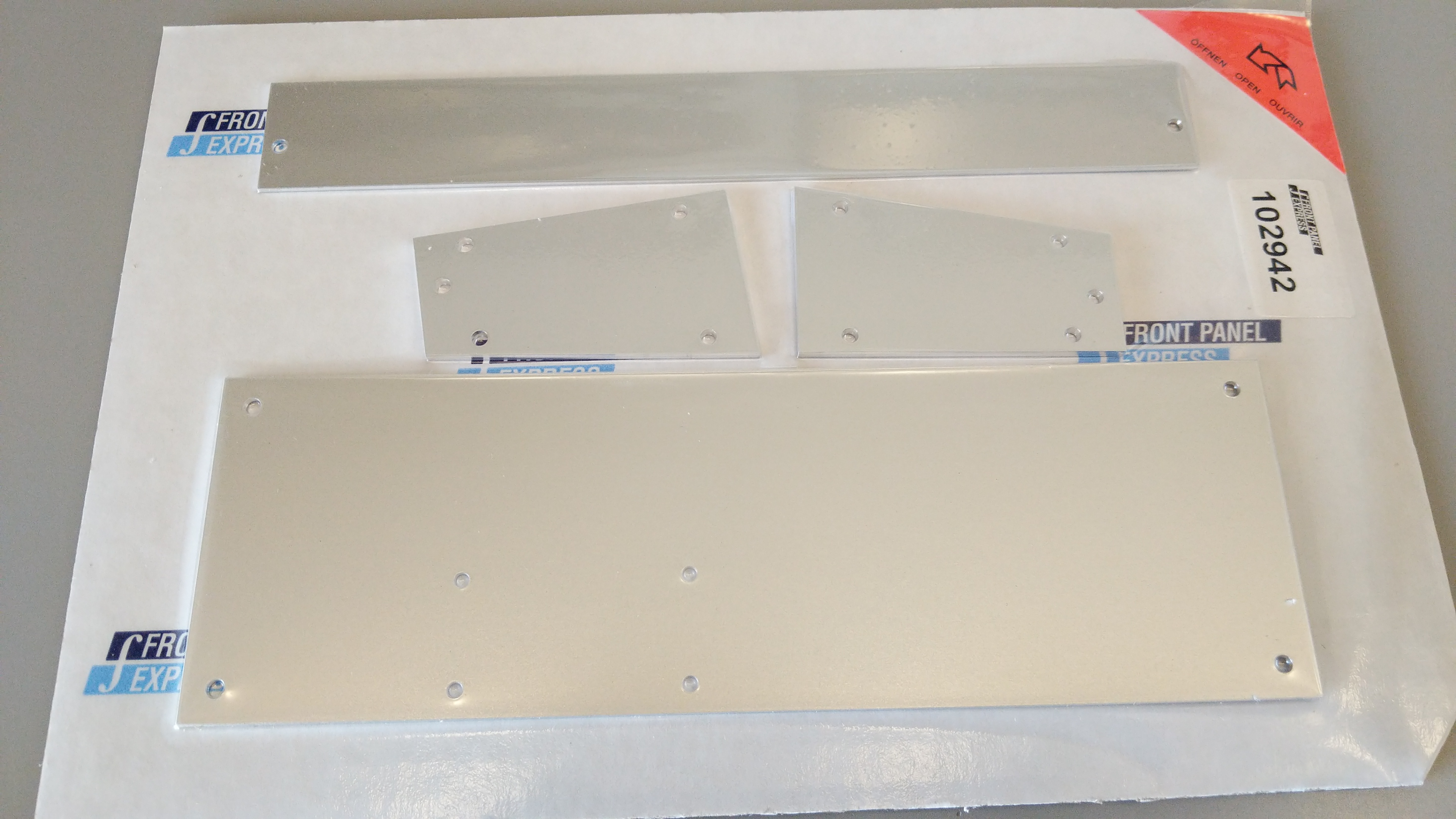
The remaining panels are back!
About 10 days later, the panels arrived and I began assembling the completed keyboard.
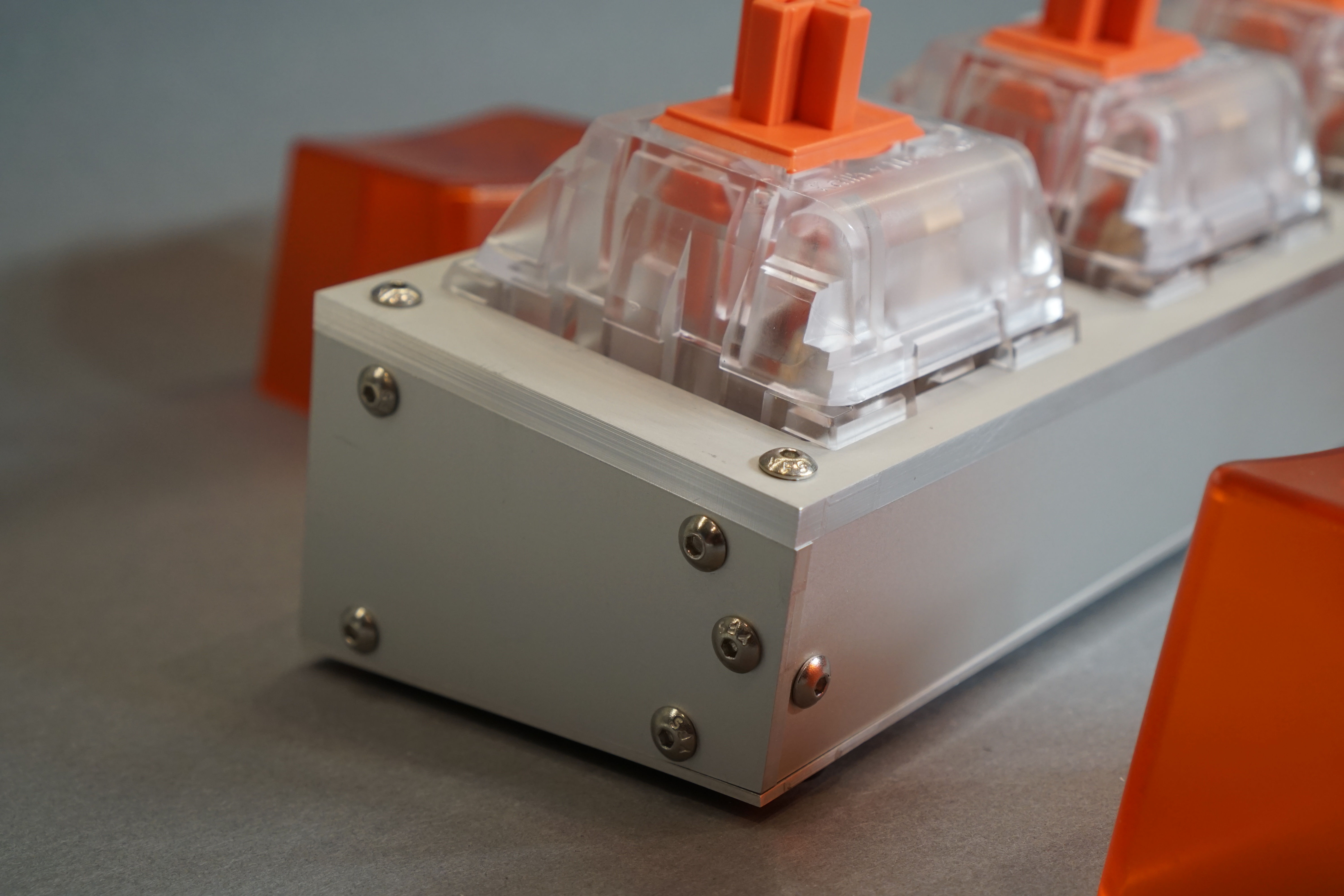
Lots and lots of screw heads are visible but they make the completed keyboard look super industrial!
Parting Shots
Here are some additional parting shots of the completed giant three key USB keyboard.
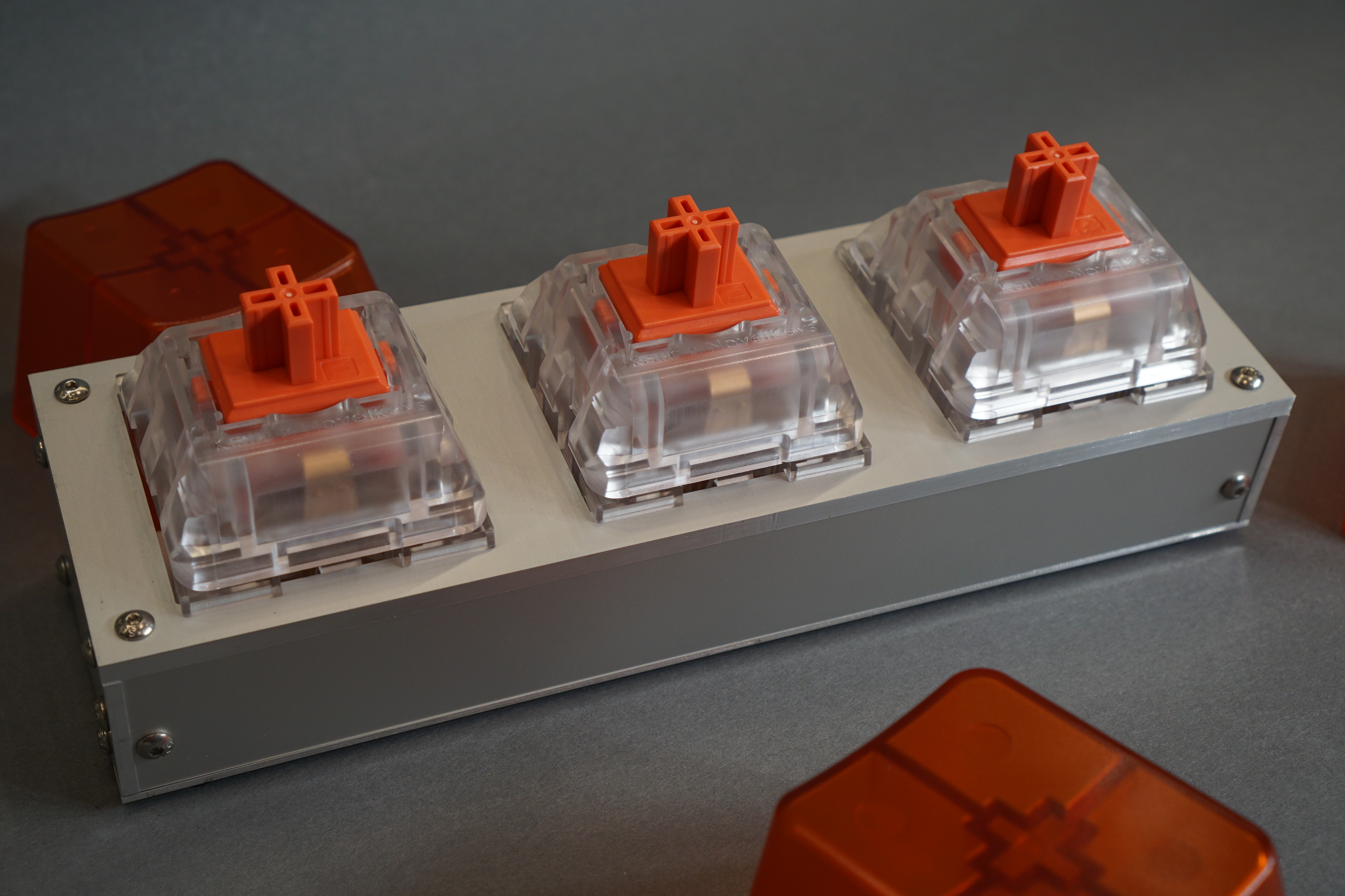
Assembled but without key caps.
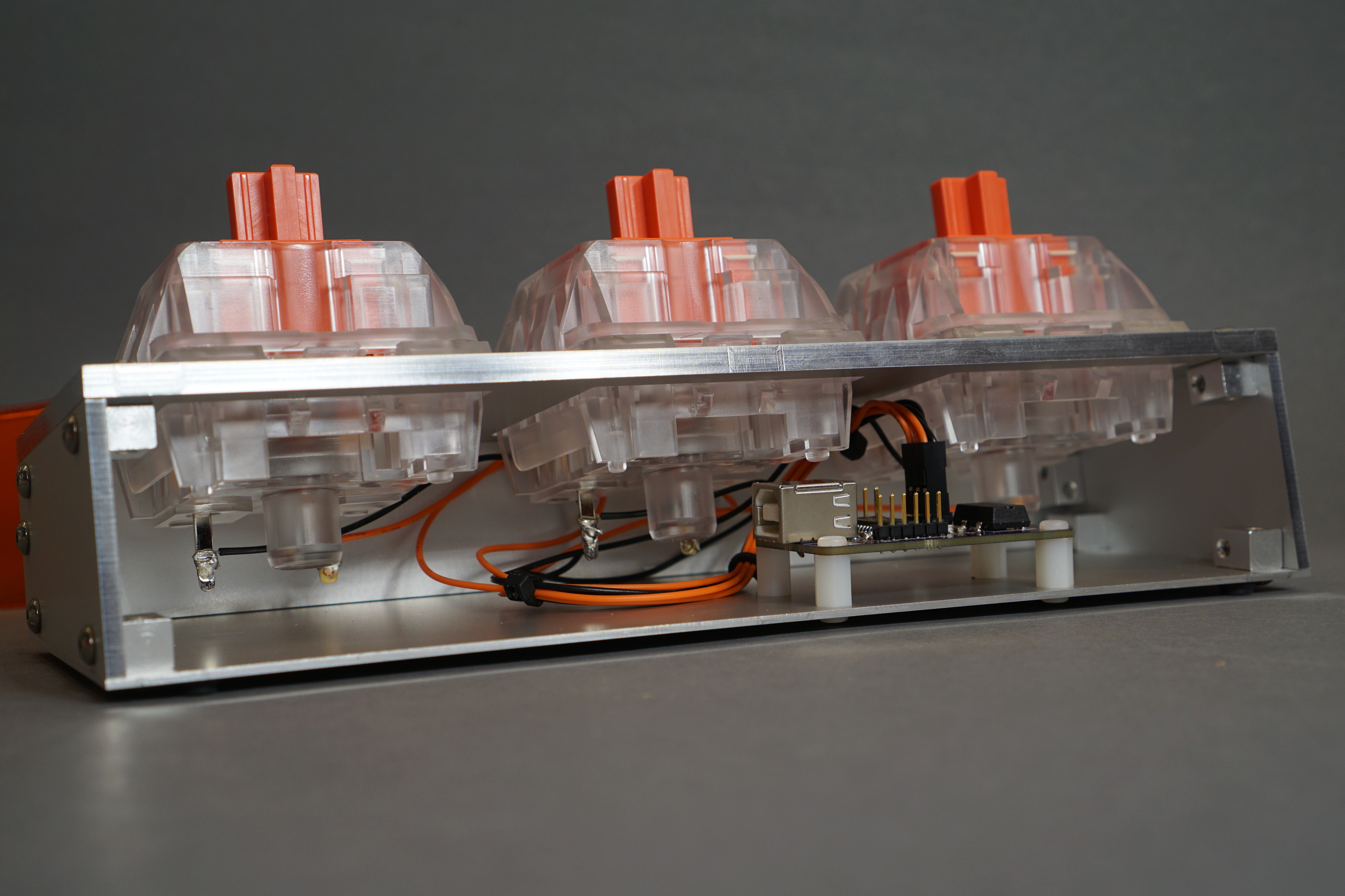
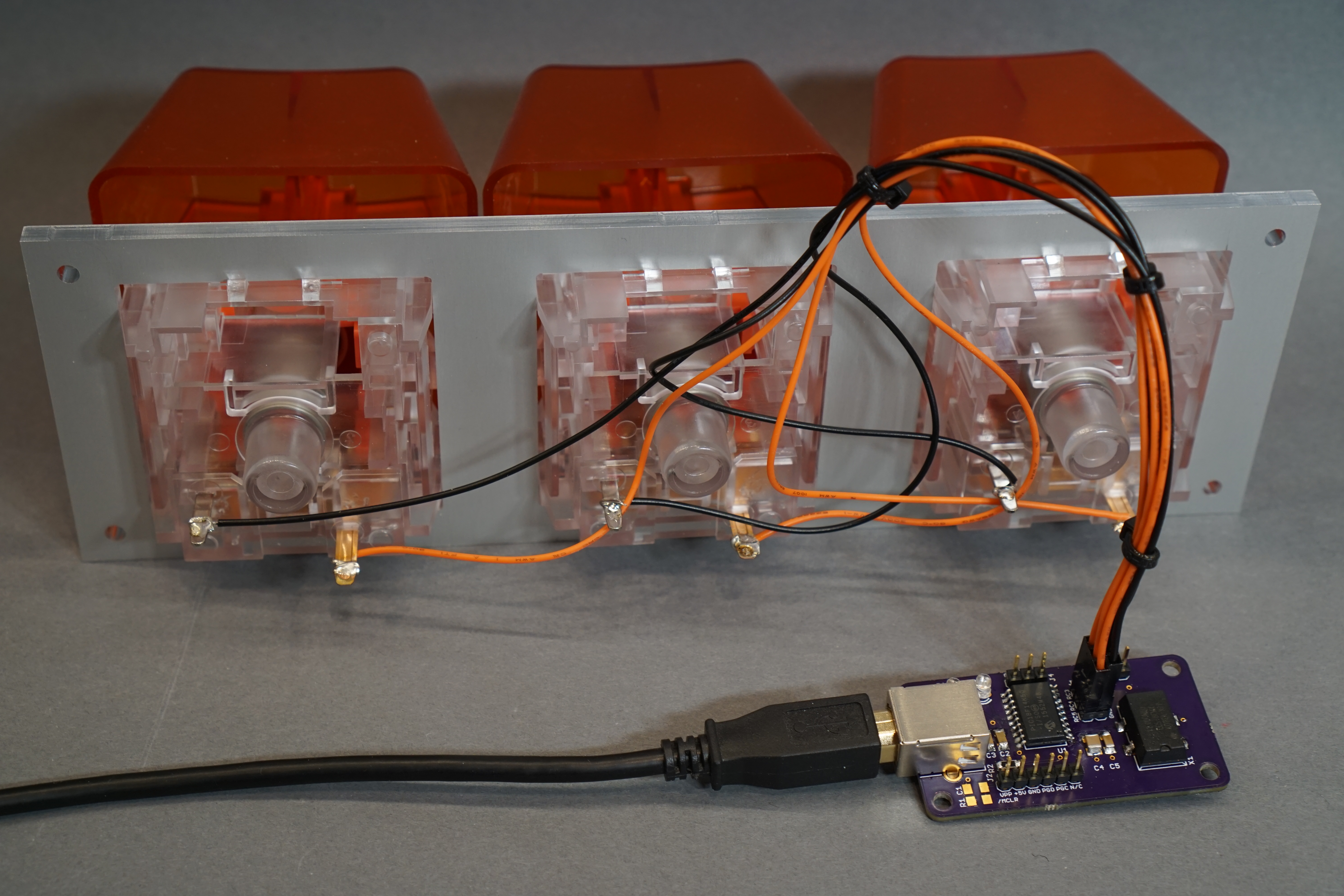
Back view showing the USB keyboard interface.
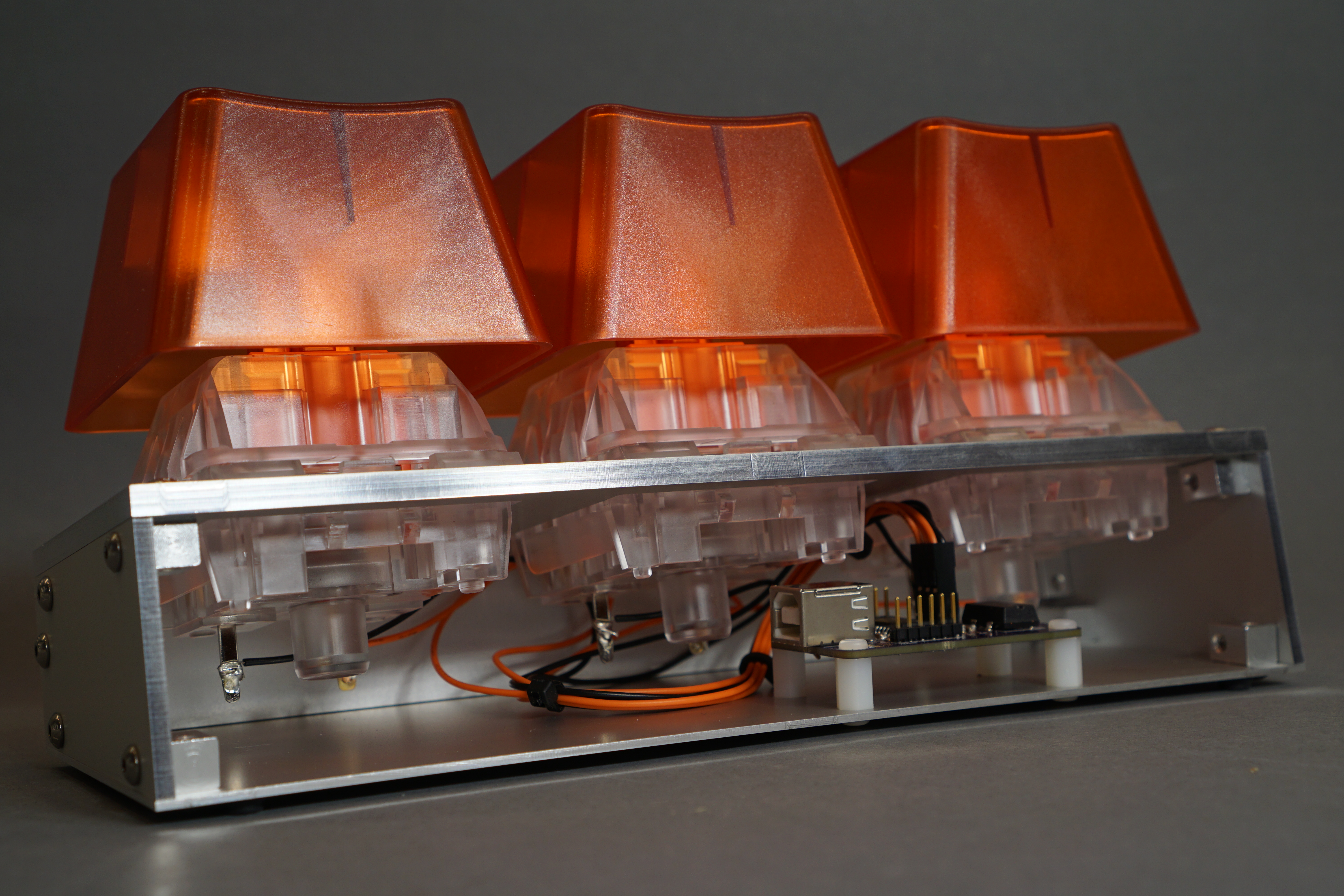
Another ack view showing the USB keyboard interface. This time with key caps.
The giant three key USB keyboard with an aluminum frame.
Thanks for reading!