

The 48-segment RGB LED board connected to the Arrow/Trenz MAX1000 FPGA board.
The 48-segment RGB LED bar graph is back. In previous posts, I wrote about using a Teensy 3.2 board and a Digilent Arty board to drive the bar graph. This time I’m driving the bar graph with a $29 Arrow / Trenz Electronics MAX1000 FPGA board. This board has a small Intel / Altera MAX10 FPGA and a few peripherals on it and is more than capable of driving the bar graph too.
Hardware
If you haven’t already, read my post Driving a SparkFun 48-Segment RGB LED Bar Graph and build the hardware described there. Once that’s done, solder a Samtec SSW-106-02-G-D-RA connector to the MAX1000 board and connect the arrow board to the display driver board. Compared to the Teensy and Arty board hardware connections, the MAX1000 board connections are the easiest because no jumper wires are required.
Development Environment
The MAX10 FPGA requires the free Quartus Prime Lite development tools. I used version 17.1. After downloading, be sure to install Quartus Prime, Platform Designer, the NIOS II software tools, and the MAX10 device support package.
Creating and Building the FPGA
The Verilog for this project is located in my sparkfun-rgb-bar-graph github repository. You’ll need all the files in the rtl-intel directory and the main.c file in the software directory. The Verilog is almost identical to the Verilog in the rtl-xilinx directory except the AXI4-Lite bus used by the Xilinx Microblaze CPU is replaced by the Avalon bus used by the Intel NIOS II CPU. The Avalon bus uses much simpler handshaking logic than the AXI4-Lite bus.
Follow the Arrow / Trenz tutorials to create a new NIOS II design using Quartus Prime and the Platform Designer. Once the tutorial design is up and running, add the avalon_rgb_bargraph Verilog as a new component and connect it to the NIOS II CPU. Be sure to define the Avalon slave bus, clock input, reset input, and conduit bus. The conduit bus should contain all the ports related to the display including the dispclk port. Be sure to export the conduit bus so that the top level Verilog wrapper can connect to it. When that’s done, the design in Platform Designer will look something like the picture below.
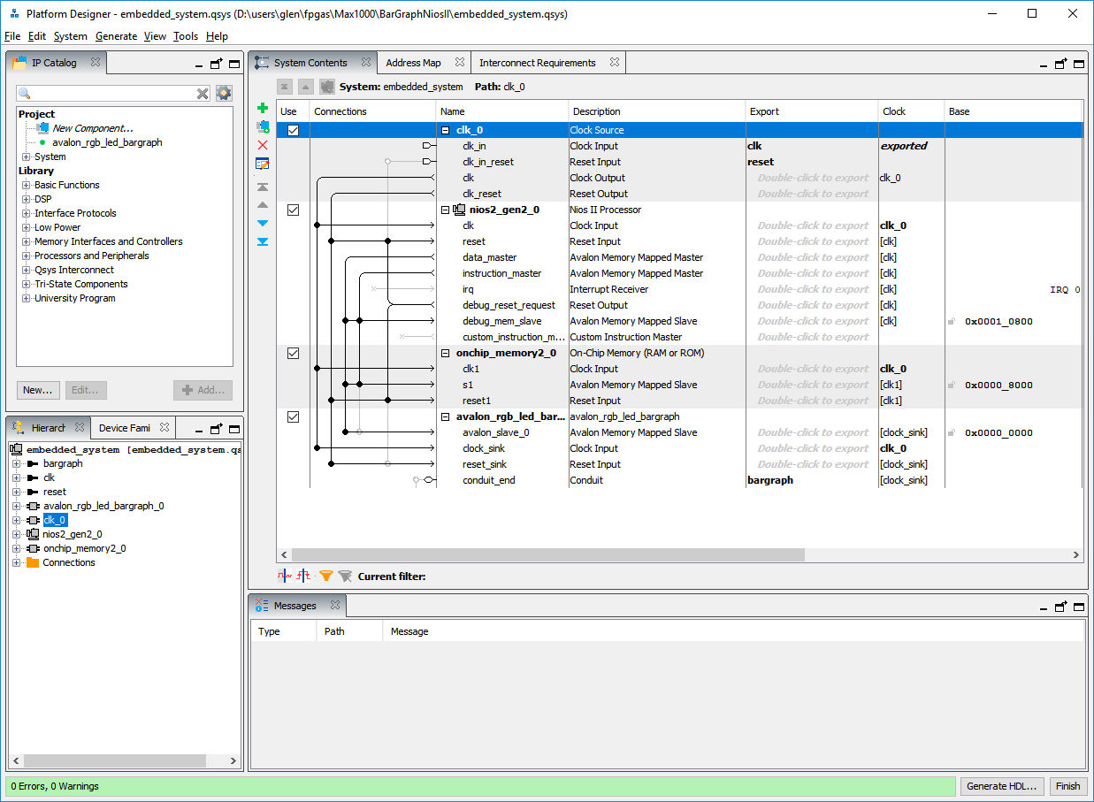
NIOS II CPU core connected to the RGB LED bar graph component in the Quartus Platform Designer tool
I initially drove both the NIOS II CPU and the display driver from a single 50MHz clock. The software was running a bit slow so I added a 100MHz clock output to my alt_pll component in the top level of the design. The 100MHz clock drives all the NIOS II related components. The 50MHz clock drives only the dispclk input on the avalon_rgb_bargraph component. The top level design file is available as top.sv in the rtl-intel directory. It contains the alt_pll component and the NIOS II embedded system.
Software Development
The easiest way to get the software going is to finish the Arrow / Trenz tutorial then add the relevant portions of main.c from my github repository to the existing software development project. Use the Quartus Prime programmer to download the .sof file to the FPGA. Once that’s completed, right click on the application project in the SDK and select Run as…NIOS II Hardware. With any luck, the bar graph should be running my stock Perlin noise demonstration project.
Conclusions
If you download both the Intel and Xilinx Verilog designs and software. You’ll notice that they’re both practically the same with the exception of the CPU bus structure in the FPGA and the accesses to registers in the software. This is one of the greatest advantages of Verilog and VHDL hardware designs. Once your design works, it’s incredibly easy to re-target your design for another FPGA or even an ASIC.
Some other notes:
1) I didn’t do any bench marking but the Microblaze CPU core feels faster than the NIOS II CPU core. The Microblaze was running at 83MHz while the NIOS II was running at 100MHz. More investigation and some bench marks would be required to confirm. Both are remarkably capable though.
2) If you’re a software developer and not sure if FPGAs are a good fit for your skills, the $29 price point on the MAX1000 board is a great way to test the waters without committing much money. It has enough IO to drive a stepper motor, some Neopixels, or a bargraph, or to capture data from various external sensors.
3) On the other hand, if you’re an experienced FPGA designer, the Digilent Arty board offers much more I/O and connectivity than the MAX1000 board for $99. Also, AXI4-Lite designs created for the Microblaze on the Arty board are incredibly easy to migrate to an ARM core on the Zybo family of boards once you need more CPU power.
4) Finally, if you’re interested in the quickest path to blinking lights, the Teensy 3.2, the Pixelmatix SmartMatrix, and the Arduino development environment are the easiest and simplest path.
The past three years, I’ve been using Xilinx FPGAs exclusively. I haven’t used Intel FPGAs since the Altera acquisition a few years ago. This $29 board was a good way for me to get back into the Intel FPGA development world.