
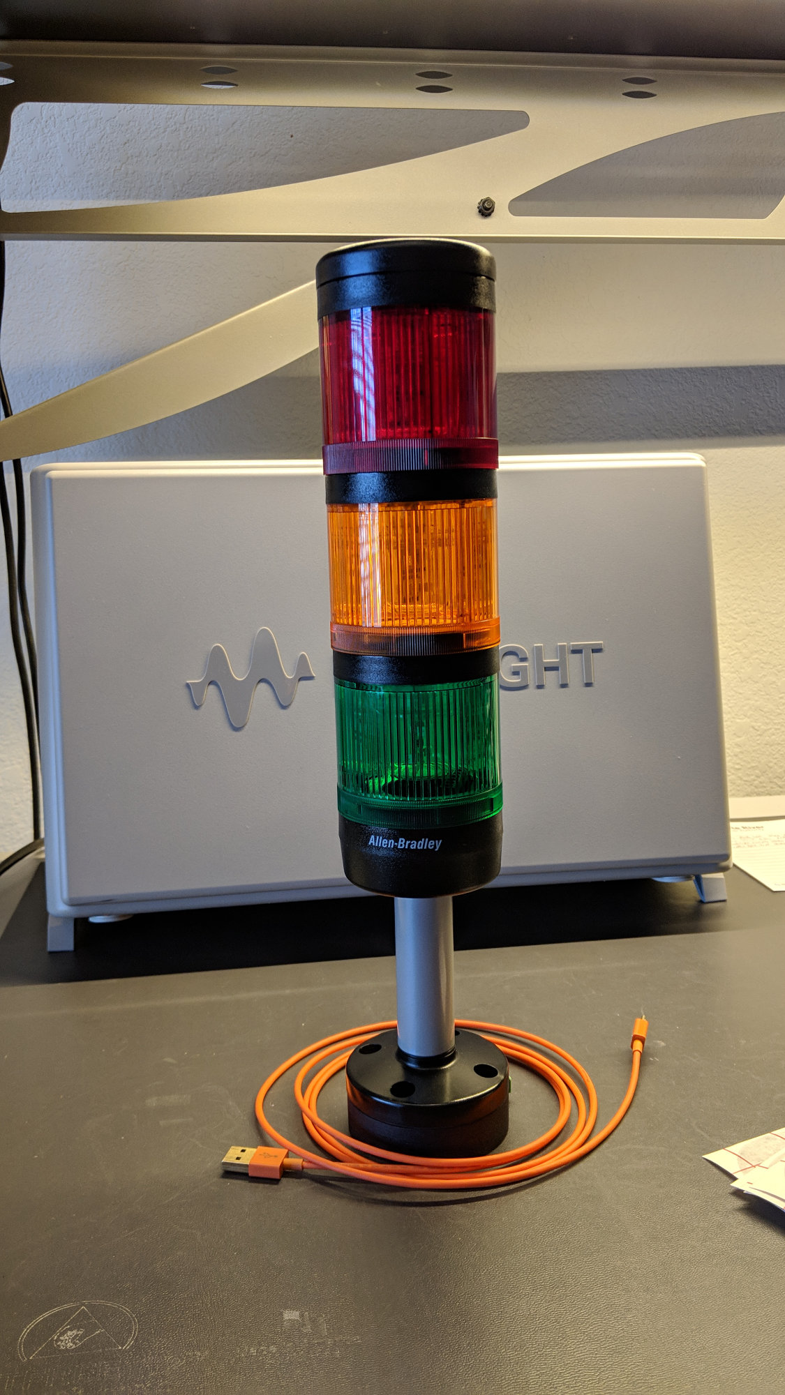
PIC16F1459-based USB industrial stack light controller. Looks pretty but will it work?
After using the PIC16F1459 to build numerous USB HID input devices including a giant keyboard, a tiny keyboard, and a big red button, it was time to see if the PIC16F1459 could be used to control outputs too. Sticking with the industrial theme, I chose to build a USB controller for a, um, stack of industrial stack lights.
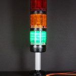
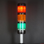
Industrial Stack Lights
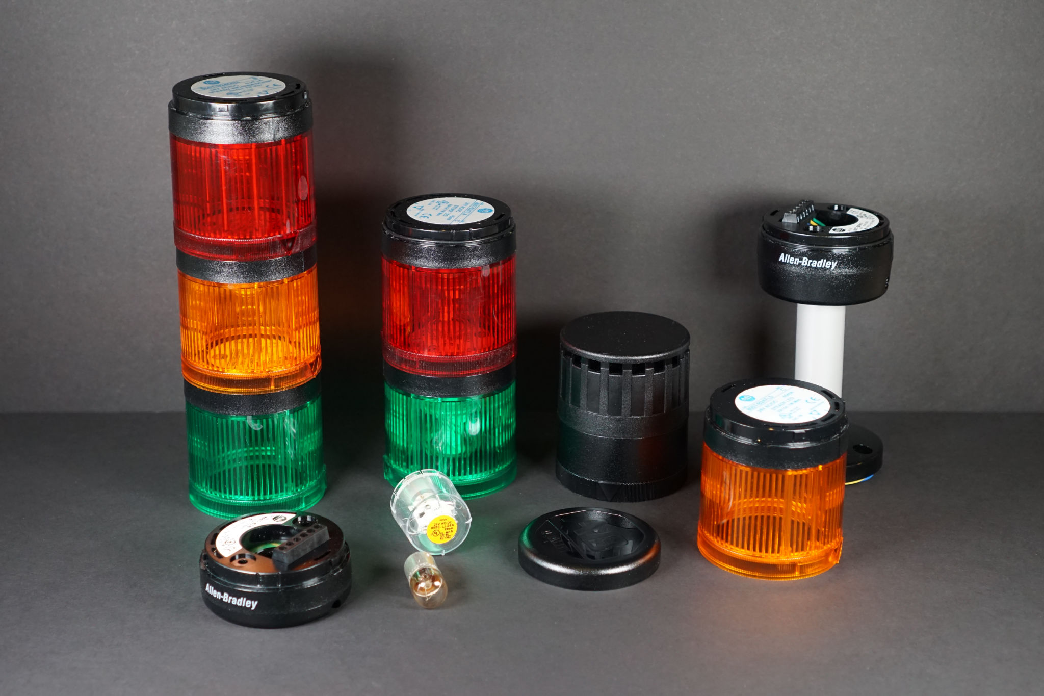
A variety of Allen-Bradley 855T industrial stack lights and parts I found on eBay.
Industrial stack lights are usually used to indicate the status of machines on production lines. Green could indicate all is functioning normally, yellow could mean the machine is running low on input material, and red could indicate the machine jammed and needs intervention.
If you buy them new, they can be quite expensive–especially for a project you’re going to build, most likely use once, and then set on a shelf. Instead, consider eBay. It’s a great place to find slightly used to new-ish industrial buttons, indicators, and stack lights on the cheap.
The key parameters when searching for stack lights are operating voltage, usually either 24VDC or 120VAC, and bulb type, either incandescent or LED. I recommend the 24VDC LED versions if you can find them.
Controlling Hardware with USB
For a simple, quick project such as this one, one does not want to have to write a custom USB driver for a Mac, PC, or Linux box. The best way to avoid writing a custom driver is to use an existing USB device class that lends itself to controlling custom hardware. The USB Human Interface Device (HID) and USB Communication Device Class (CDC) device classes both support controlling custom hardware.
USB HID Output Reports
USB HID output reports are data blobs sent from an application running on a PC or other USB host to a USB HID device such as a keyboard or mouse or game controller. If you have a fancy gaming keyboard with tons of RGB LED lights, the application software on the PC could use USB HID output reports to control the state of the RGB LEDs on the keyboard. As another example, the Sony PS3 SixAxis DualShock controllers use USB HID output reports to activate the shaking of the controller.
The cool part about USB HID output reports is the USD HID device receives complete packets. There’s no parsing of a data stream required. You get a complete packet, pull the bytes out of the packet, and control the hardware as necessary. The downside is USB HID output reports need application software running on the USB host PC to send them which, of course, requires developing said application software.
USB CDC
Another USB device class that is suitable for controlling external hardware is the USB CDC device class. The USB CDC device class is typically used to implement USB to serial converters or to implement serial consoles on development boards like the Adafruit Feather series.
The upside with the USB CDC device class is you can launch a serial console and immediately begin interacting with your hardware. No application development required. The downside is you have to have software on your hardware that parses the faux serial data stream to find the bytes that should control your hardware.
Selected Method
I decided to go with the USB CDC method for this project. I did not want to have to develop a custom application on my PC to control the hardware. Being able to launch a serial console and immediately interact with the hardware was very appealing. One day I will have to try sending a USB HID output report from a PC. Just not today. I’ve sent them from numerous embedded USB hosts; just never a PC USB host.
Enclosure Design
After thinking about the project some, I decided I wanted a red, amber, and green light, a cap, and the 10cm pole base. The 10cm pole base would mount to the top of an enclosure that holds the USB electronics. I found the stack light parts on eBay, ordered them, found their data sheets and 3D models on the Rockwell Automation / Allen-Bradley website, and set about designing the enclosure for the electronics using Autodesk Fusion 360.
Parameterized 3D Modeling
Fusion 360 supports parameterized 3D models. With a parameterized model, you create a bunch of parameters, assign the parameters default values, then use the names of those parameters in place of numeric values as you create the 3D model. It requires some planning ahead but makes changing the height or diameter or wall thickness of your model later almost trivial.
For this enclosure, I knew it’d have a diameter, a height, a wall thickness, four screw holes, four recesses to hold some M5 nuts, and those screw holes would be a certain distance from the center of the base. Here’s the parameters I created using the modify -> change parameters command in the model view:

USB industrial stack light enclosure parameters.
At this point, you’re ready to create your 3D model. Create a component, create a sketch inside the component, then as you’re laying out the initial geometry of your model on the sketch, use the parameter names from above instead of a numeric value for each dimension on the sketch. If you come back later and change a parameter, the dimensions on the sketch and the 3D bodies created from the sketch will update automatically.
Of all the parameters shown in the dialog box above, the enclosure height parameter was the most important and the one subject to changing the most. I did not know how tall the enclosure needed to be until I had the PCB designed and the connectors and screws for the project picked out.
Initial Design of the Enclosure
After creating the parameters, drawing a sketch based on the parameters, and extruding parts of the sketch, the enclosure looked like the images in the pictures below. This is not the final version of the enclosure, however, because there’s no place for the USB and power connectors.
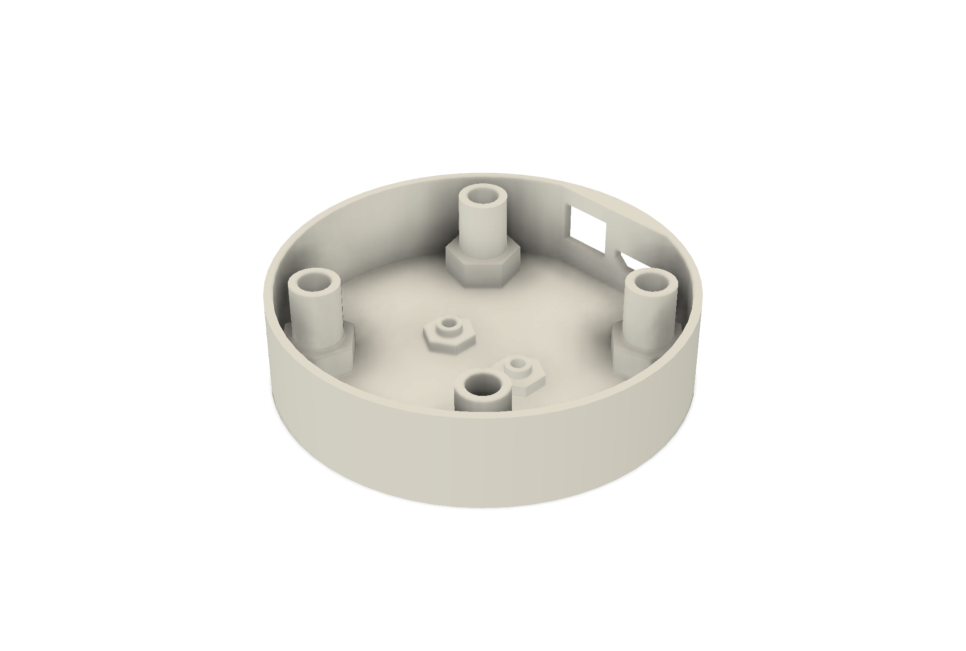
Based on the dimensions in the data sheet for the 855T series 10 cm stack light base, the four posts inside the enclosure image below line up with the four screw holes in the stack light 10cm base. M5 screws are threaded through the 10 cm base, into these posts in the enclosure, then secured with a nut in the hexagonal recess in the bottom of the enclosure.
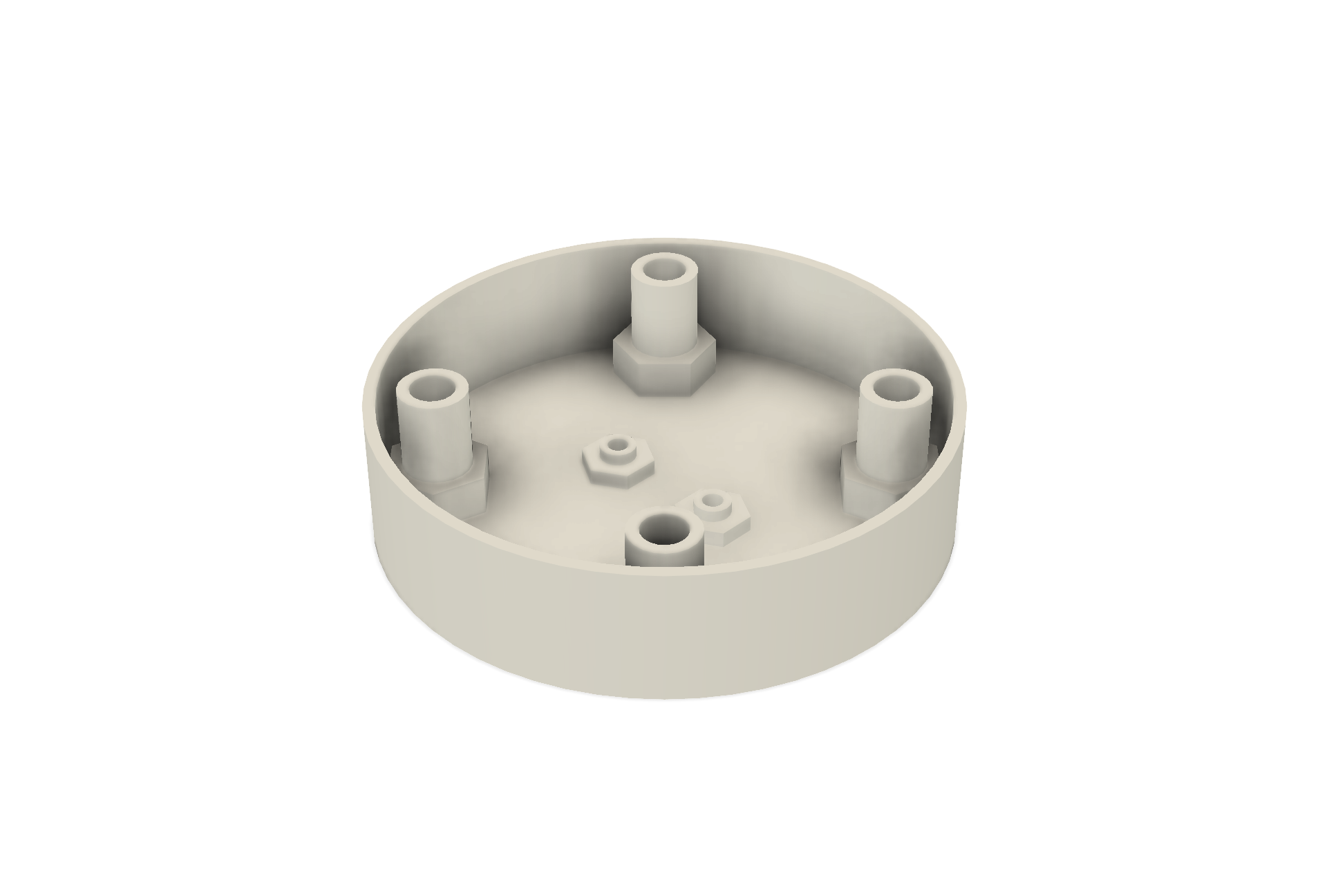
An early version of the enclosure as viewed from above.
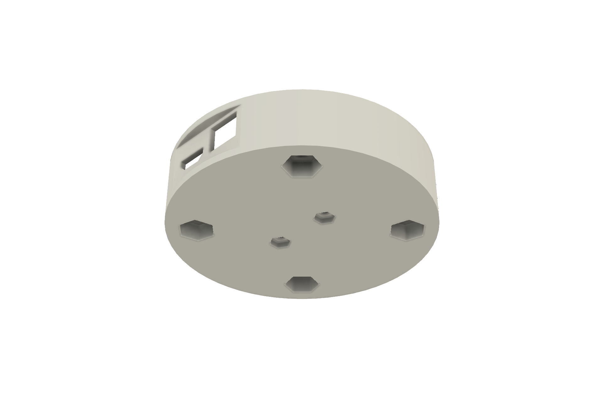
Here’s the same version of the enclosure as viewed from the bottom. The hexagonal recesses each hold an M5 nut that mates with an M5 screw threaded through the stack light 10 cm base and the enclosure. The smaller posts and nut recesses are for 2-56 x 1/4″ screws to hold a circuit board in the bottom of the enclosure. Based on the data sheet and 3D model for the stack light base, I decided to adjust the height of the enclosure to 17mm. This would allow the use of M5 x 20mm socket cap screws to hold everything together.
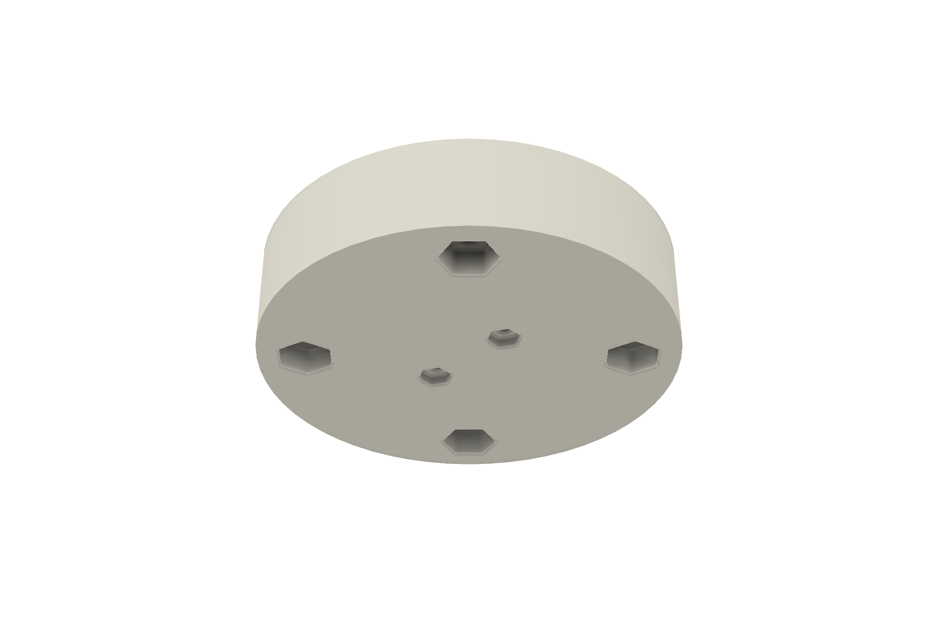
An early version of the enclosure as viewed from the bottom.
Electrical / Mechanical Codesign
At this point, I had an enclosure that was sized to mount underneath the stack light’s base. The enclosure would be secured with four M5 x 20mm screws and M5 nuts. The next step was to design a circuit board to hold the electronics. The circuit board would also need a power connector for +24VDC to power the stack lights and a USB connector to talk to the host PC.
I used the inspect -> measure command in the model view to measure the internal dimensions of the enclosure. The circuit board needed to be 24mm wide to fit between the posts and could be up to about 60mm long. I drew a board outline in Autodesk Eagle with these dimensions and placed a Phoenix 1803277 connector for +24VDC power and a Wurth 629105136821 connector for the USB connection to the PC on the board.
I then used Eagle to export a 3D model of the board into Fusion 360. I placed the board inside the enclosure and looked at the alignment of the square edge of the board, the rounded interior of the enclosure, and the placement of the connectors. They fit vertically but there was no way a USB cable could mate with the USB connector or the power input’s pluggable screw terminal block could mate with its header connector.
The Connector Notch
At this point it became obvious that the outside of the enclosure needed to be flat where the connectors protruded through the enclosure. Also, the inside of the enclosure had to be flat where the circuit board butted up against it. With a bit of work, I created a 1.5mm thick flat wall offset 0.5 mm from the edge of the circuit board.
This almost worked. The problem is that where the stack light base met the enclosure there was now a gap. The final solution was to include a 2mm tall circular portion above and below the flat portion as shown in the image below. This allowed the circuit board to butt up against a flat interior wall, it allowed the connectors to mate without interference, and it had a good fit to the stack light base when the stack light base was mounted to the top of the enclosure. The bottom 2mm circular portion is just for symmetry and aesthetics.
The image below shows the final notched enclosure and the circuit board with connectors mounted inside the enclosure. The cutouts for the connectors were created using the same offset plane, sketch, and extrude technique that I used to create the connector cut outs for the DMX RGB light project.
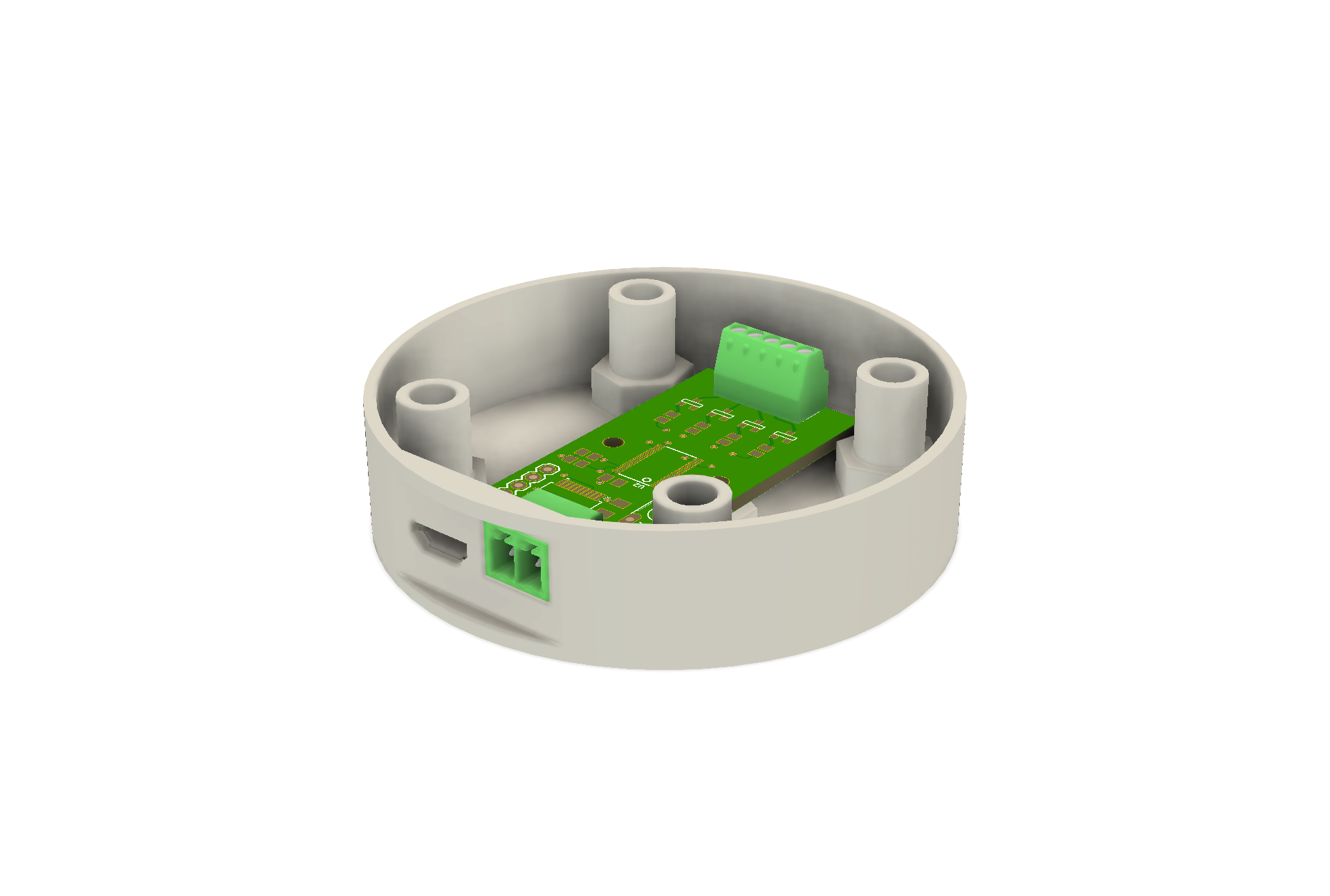
View of the model from the back which shows the notch in the enclosure and the connectors protruding through the notch.
The last item to do before ordering a 3D print was to find 3D models of the connectors, stack light base, and USB cable then assemble the stack light and enclosure in Fusion 360 to check that everything fit together without interference. The image below shows everything assembled. If the Phoenix connector had not cleared the circular part of the enclosure directly above it, I would have needed to adjust the height parameter to 19mm and used M5 x 22mm screws to assemble the project.

Stack light base, enclosure, connectors, and cables.
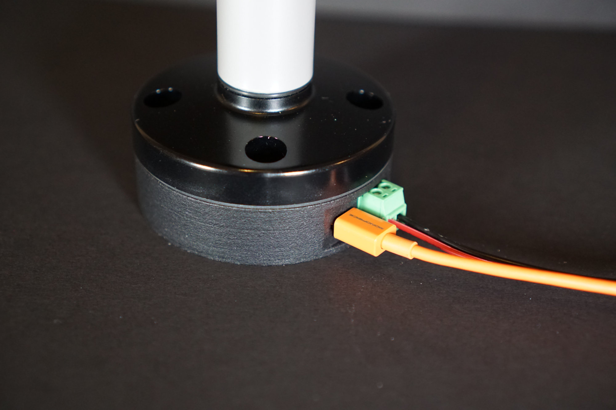
Here’s how the notch and connectors turned out in real life:
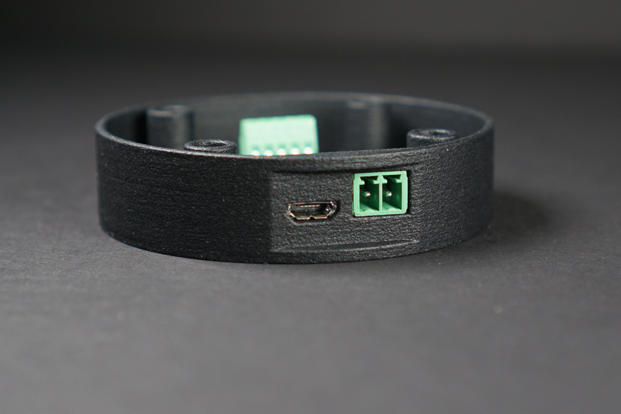
Close up of the notch and connectors.
Final Design of the Enclosure
Here’s the final design of the enclosure as viewed from the top:
Base / enclosure as viewed from the top.
Here’s the final design of the enclosure as viewed from the bottom:
Base / enclosure as viewed from the bottom.
Hardware Design
Now that the enclosure and PCB size were finalized it was time to design the electronics. One requirement was to be able to fade the stack lights in and out and control their brightness. The PIC16F1459 only has two hardware PWM channels though. To PWM three different colored stack light segments would require external hardware or some crafty software techniques. I decided to throw hardware at the problem.
The NXP PCA9685 is a 16-channel, 12-bit PWM I²C-bus LED controller. It can control 16 channels of 12-bit PWM over an I²C bus. The I²C bus only requires two IO pins on the PIC16F1459. A quick check of the PIC16F1459 data sheet confirms that the PIC supports I²C using two dedicated pins on the package. The I²C SCL clock signal is on pin RB6 and the I²C SDA clock signal is on pin RB4. This design will use four of the PCA9685’s 16 channels and leave the remaining channels unconnected.
Here’ s the schematic for the design:
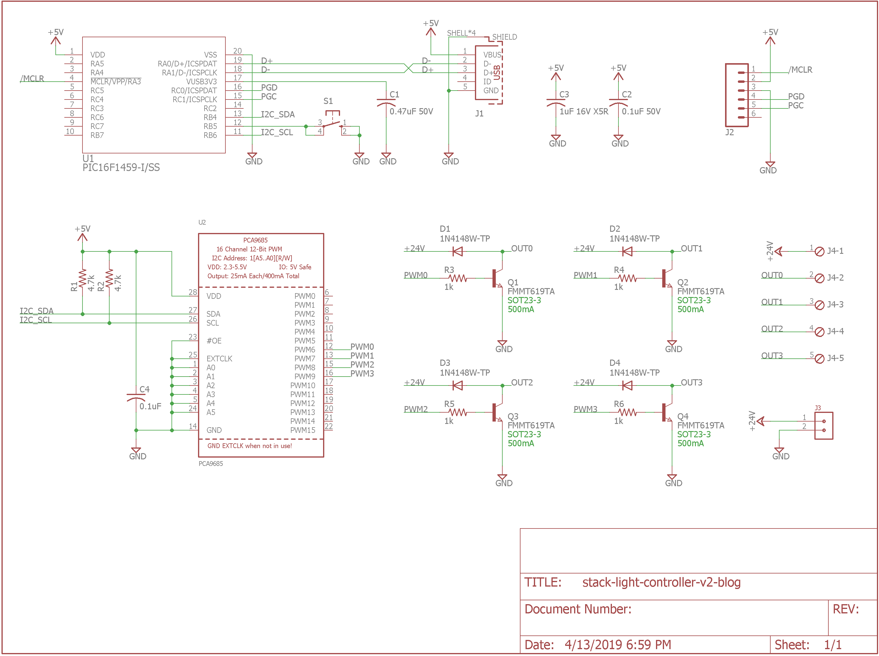
USB stack light controller schematic. Needs ESD protection. Grrr.
Here’s the finished board layout:
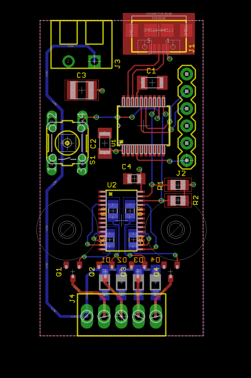
USB stack light controller board layout.
And some Oshpark renders of the board:
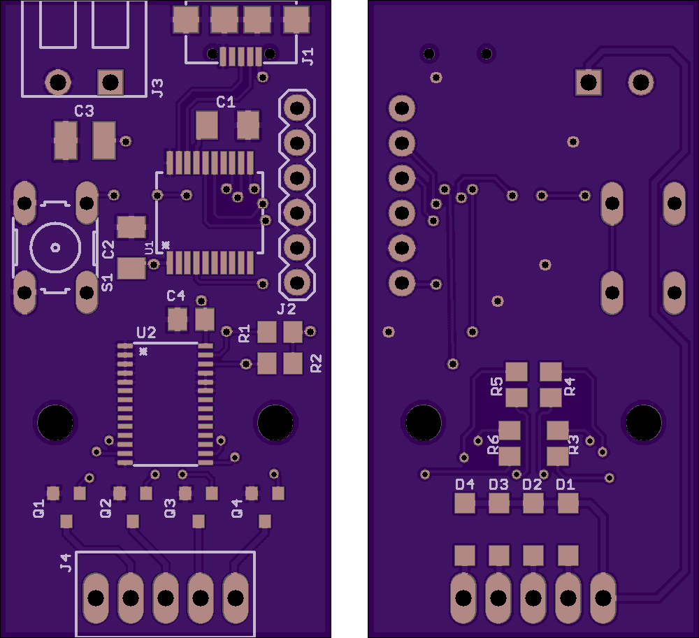
Oshpark renders of the USB stack light controller board.
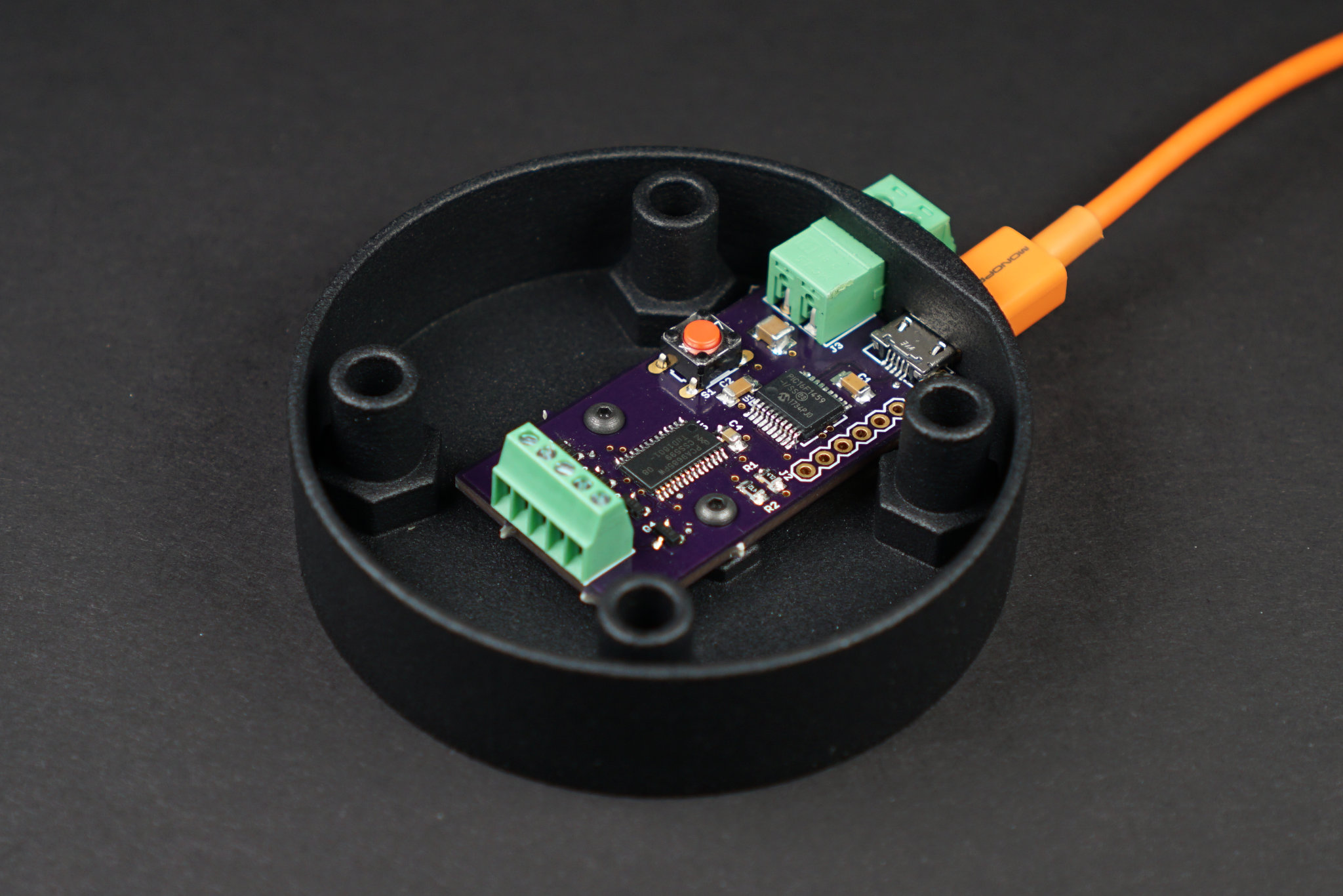
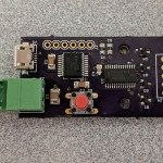
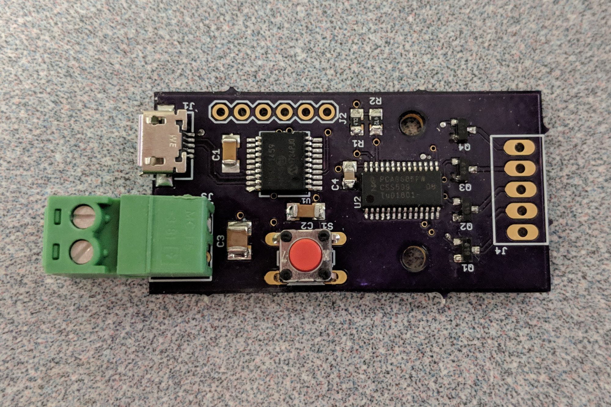
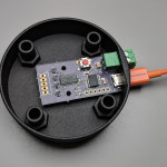
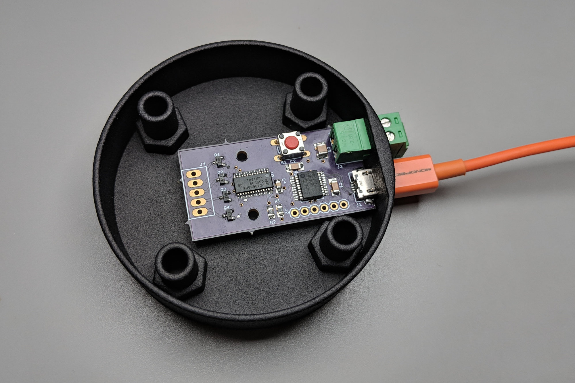
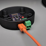
Here’s the almost completely assembled board in the finished enclosure:

Almost completely assembled board.
Software Design
The software is based on the Microchip Library for Applications CDC Basic PIC16F1459 demonstration code. To this code, I added I²C code based on the example here, some PCA9685 configuration code, and a small CLI for interacting with the user in a terminal.
Controlling the PCA9685
The PCA9685 code has three functions defined. The first initializes the addressed PCA9685 over the I²C bus and sets all 16 channels to off:
void PCA9685_Init (uint8_t addr)
{
    I2C_Master_Start ();
    I2C_Master_Write (addr);
    I2C_Master_Write (MODE1);
    I2C_Master_Write (0x30);
    I2C_Master_Stop ();

    I2C_Master_Start ();
    I2C_Master_Write (addr);
    I2C_Master_Write (PRESCALE);
    I2C_Master_Write (0x02);
    I2C_Master_Stop ();

    I2C_Master_Start ();
    I2C_Master_Write (addr);
    I2C_Master_Write (MODE1);
    I2C_Master_Write (0x20);
    I2C_Master_Stop ();

    for (uint8_t channel = 0; channel < 16; channel++) {
        PCA9685_SetPWM (addr, channel, 0);
    }
}
The second function takes an I²C address, a PCA9685 channel, and a level and converts the level to the on time and off time values needed by the PCA9685. The input level is a value from 0 for completely off to 4095 for completely on:
void PCA9685_SetPWM (uint8_t address, uint8_t channel, uint16_t v)
{
    v &= 0xFFF;
    if (v == 4095) {
        // fully on
        PCA9685_SetRaw (address, channel, 4096, 0);
    } else if (v == 0) {
        // fully off
        PCA9685_SetRaw (address, channel, 0, 4096);
    } else {
        PCA9685_SetRaw (address, channel, 0, v);
    }
}
This above function is based on the Adafruit code here.
The last function takes the values computed by the previous functions and sets the channel of the addressed PCA9685 to the specified levels:
void PCA9685_SetRaw (uint8_t address, uint8_t channel, uint16_t on, uint16_t off)
{
    I2C_Master_Start ();
    I2C_Master_Write (PCA9685_I2C_ADDRESS);
    I2C_Master_Write (LED0_ON_L + 4 * channel);
    I2C_Master_Write (on);
    I2C_Master_Write (on >> 8);
    I2C_Master_Write (off);
    I2C_Master_Write (off >> 8);
    I2C_Master_Stop ();
}
As a side note, the I²C address of the PCA9685 is really 0x40. These I²C communication routines though require the address to be in the upper 7 bits of the address byte. This is why the address is #defined as 0x80 instead of 0x40.
The Command Line Interface
Remember the desire to interact directly with the hardware using a serial console window? This requires that the CDC device have a command line interface (CLI). I added a very simple CLI to the APP_DeviceCDCBasicDemoTasks function inside the demo code. The CLI accepts up to 72 characters per line. It supports the printable ASCII characters, backspace, and return.
When the user hits the return key, the CLI attempts to parse a decimal channel number and decimal level value from the entered command line. If successful, the CLI sets the specified channel of the PCA9685 to the specified level and returns “Ok” to the user. If not successful, the CLI returns “Err” to the user. Here’s an example terminal session with the stack light controller:
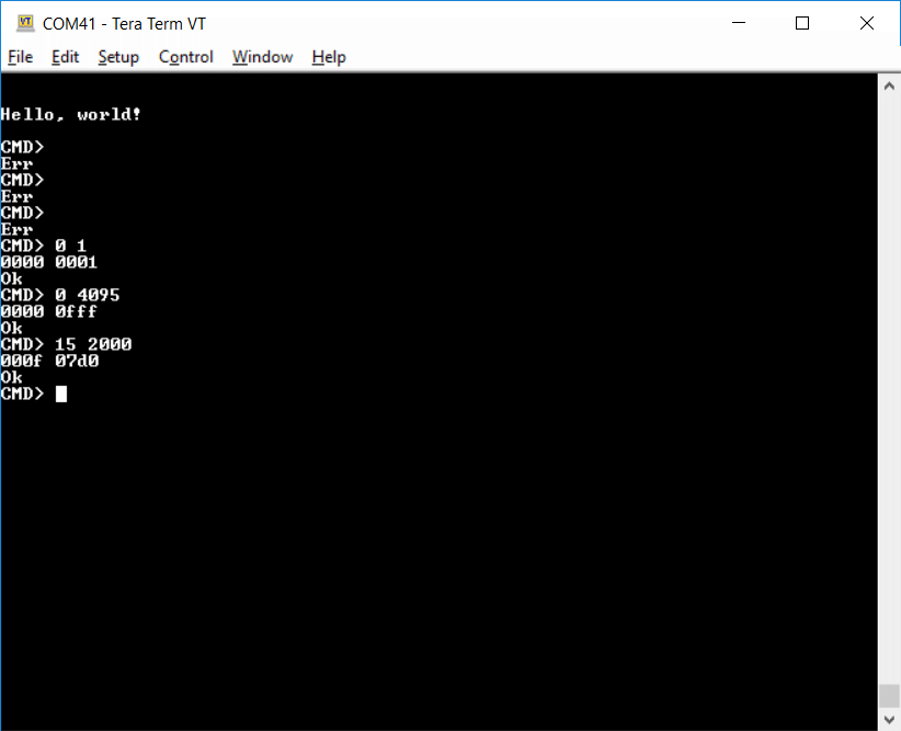
CLI Terminal Session
The first successful command sets channel 0 to 1. The next one sets channel 0 to 4095. The last one sets channel 15 to 2000. A future improvement to the CLI would be to add commands to support blinking and fading the stack lights on and off.
Testing the Software
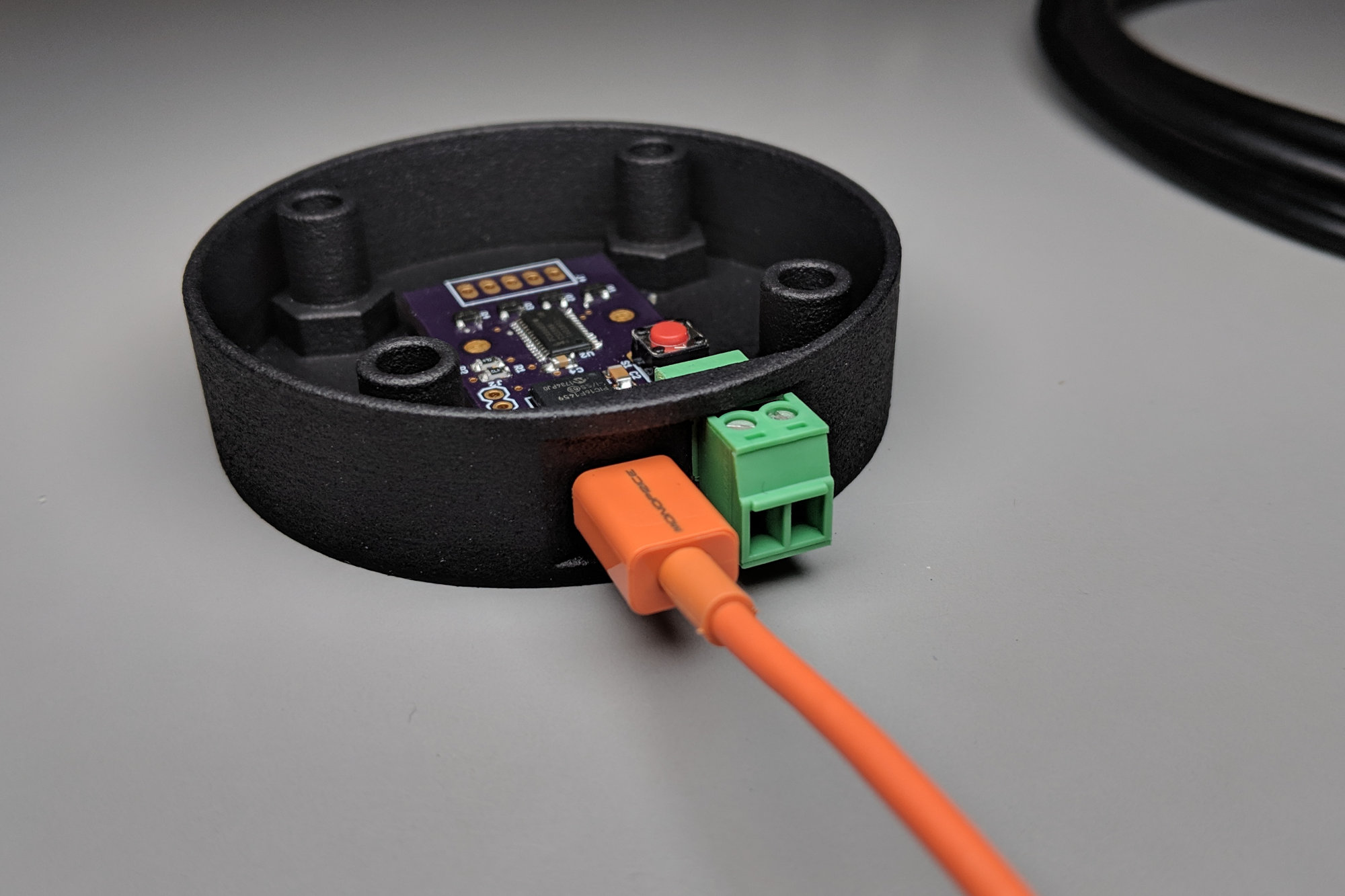
Before completely assembling everything, I did test the software with a single light:
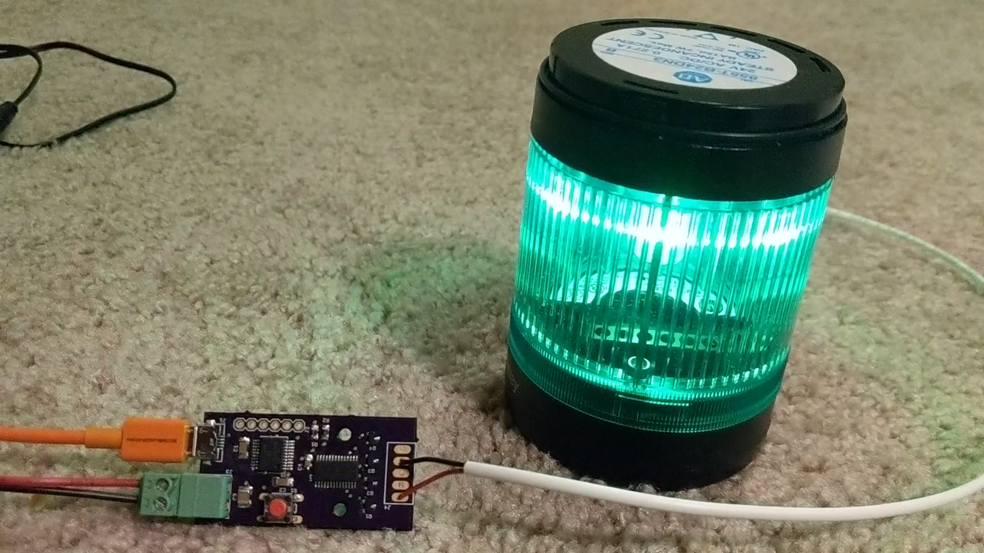
Another example of my most excellent ESD precautions while I test the I2C and PCA9685 software.
This verified the CLI, I2C, and PCA9685 were all operational.
Assembly
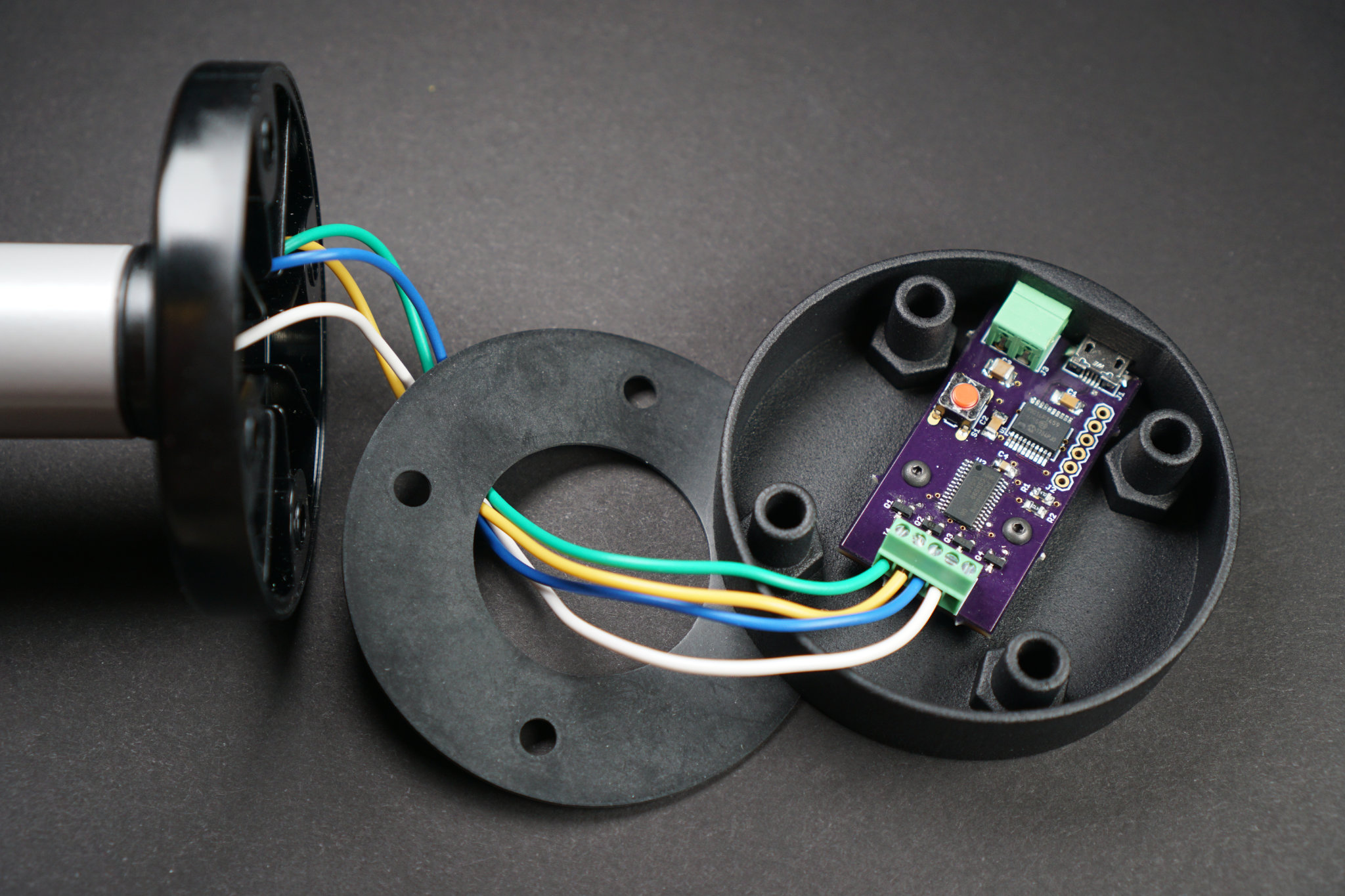
Well, that’s inconvenient. Next build gets a pluggable terminal block.
The final step was to assemble everything. The first time I assembled everything, I forgot the rubber gasket. It’s not really needed in my non-industrial home workshop environment it but does provide a better transition between the base and the enclosure. In a future version of this project, I should replace the screw terminal strip with a small pluggable terminal block to make assembly and disassembly easier. Here are a few more photos of the project in various stages of completion. Thanks for reading!
-
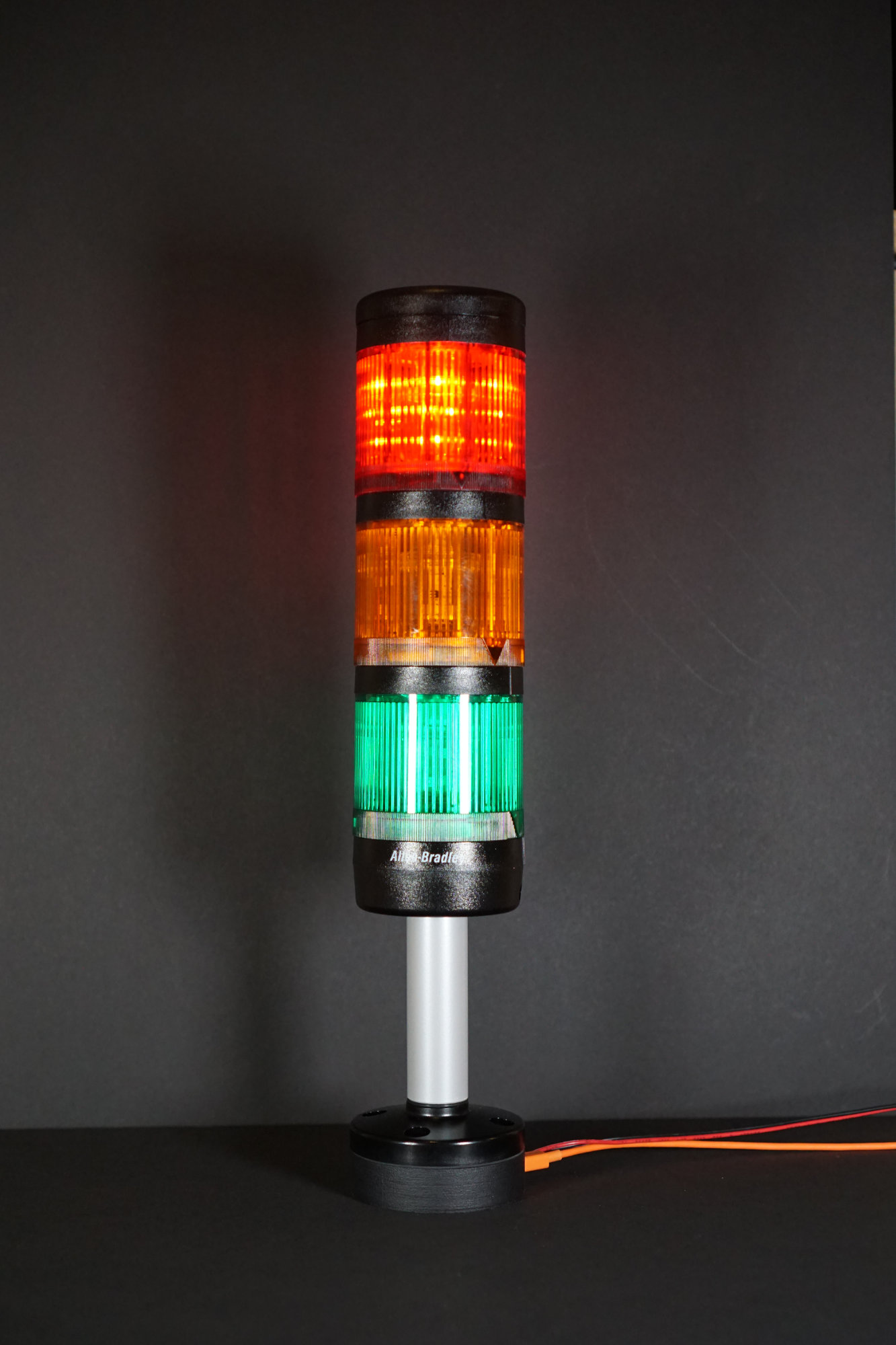
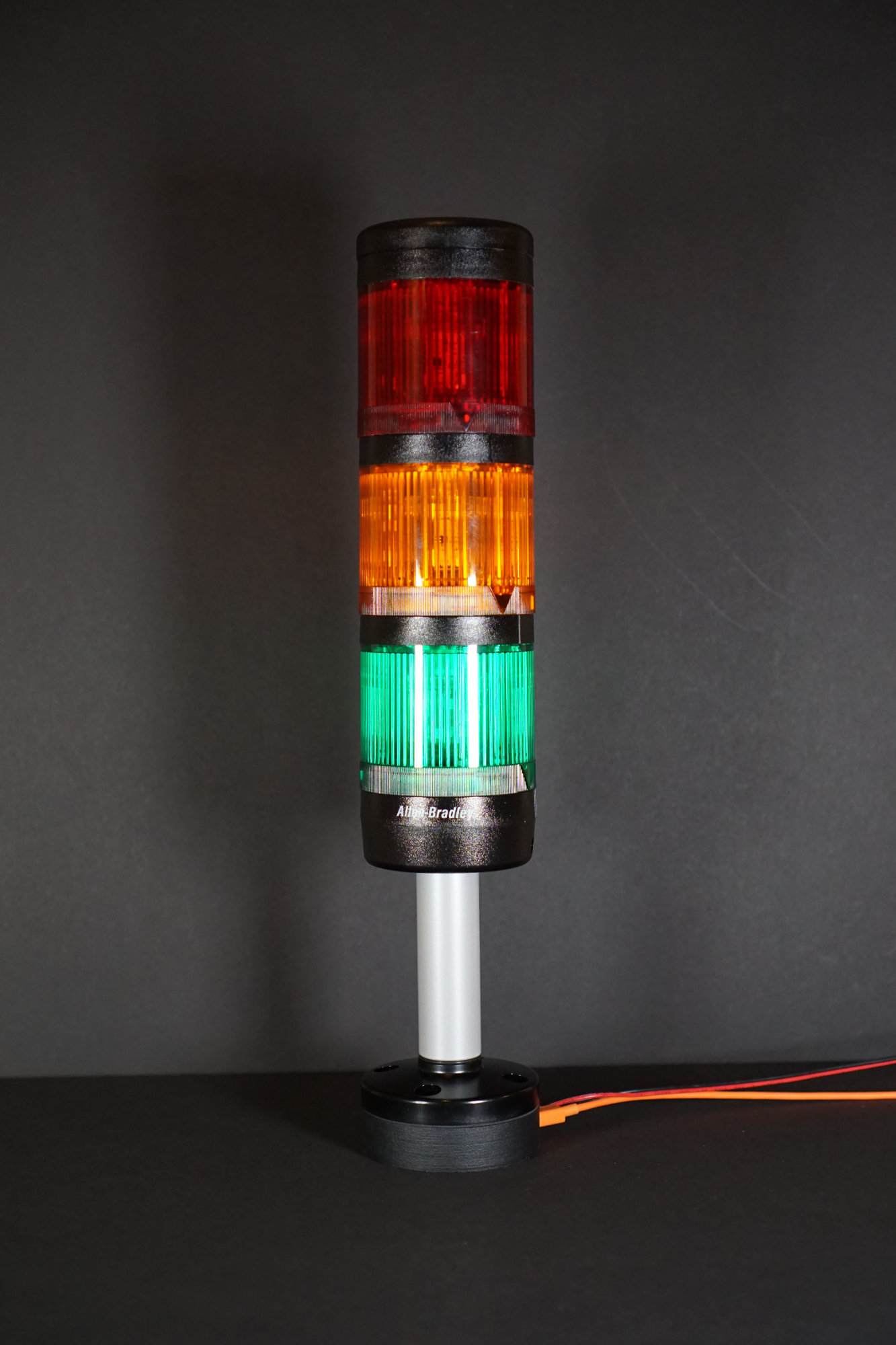
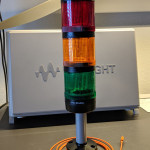
- Green

-
- Red
-
- All

-
- None
-
- On the bench
-
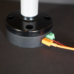
- Base / enclosure interface
-
- Board
-
- Board and enclosure
-
- Board and enclosure
-
- Board and enclosure and light
Code and Models
Code and models are available upon request. They’ll most likely end up on github.com/bikerglen at some point.