
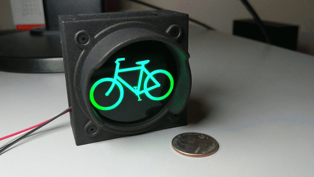
Completed bicycle traffic signal cycling through traditional traffic light colors. This is the older, narrower version of the hood.
This is the first in a series of posts describing how to build a Wi-Fi enabled bicycle traffic signal. In this first part, we’ll go over the required parts, using a 3D printing and laser cutting service to build the needed mechanical components, and assembling the traffic signal. In the second and third posts, we’ll connect the bicycle traffic signal to a Particle Photon and Adafruit Feather M0 Wi-Fi respectively to enable the traffic signal to be controlled via Wi-Fi. In the final post, we’ll build our own control electronics, add a small base to house the new electronics, and expand the signal to three lights.
Inspiration
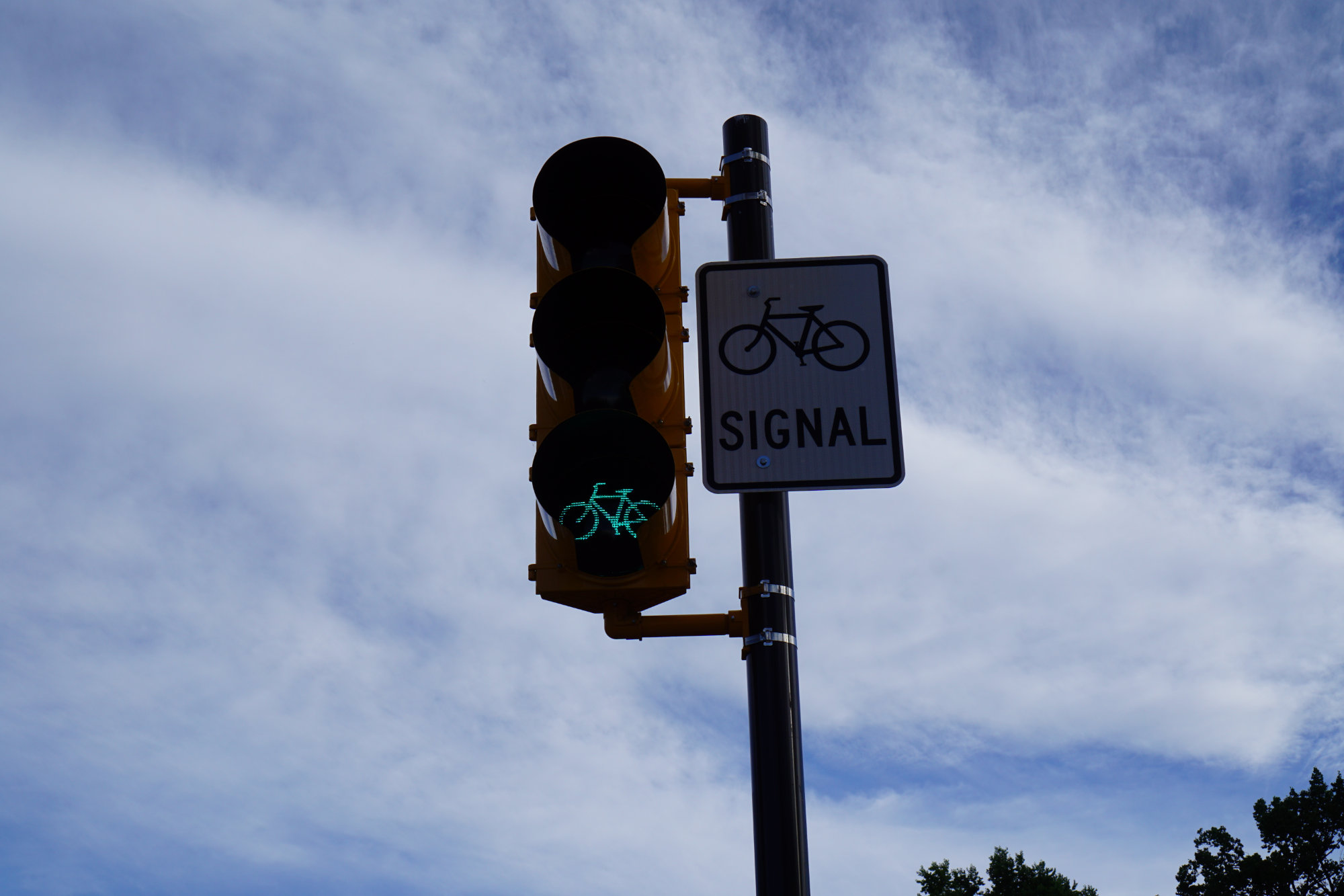
The inspiration for this project was a real bicycle traffic signal located in Fort Collins, Colorado. The picture would be better exposed but someone started casing my bike while I was taking photos so I had to get back on it and run.
The inspiration for this project was a real-life bicycle traffic signal located in Fort Collins, Colorado. This signal was installed in Fort Collins in 2014 or 2015 as part of an upgrade to the city’s central transportation corridor to include roads, sidewalks, bicycle paths, and a dedicated route for their Max bus service.
After seeing the signal, I decided I needed one for my house and I wanted it to do something interesting. After a bit of thinking, I decided that showing trail status or weather conditions and giving a red light, yellow light, or green light as to the riding conditions for the day would be the ideal use. The only problem is that traffic signals are expensive and huge. They easily cost over $1000 per face and use 12″ globes making a three light signal over three feet tall.
Clearly it was time to find another solution. I settled for building my own 65 mm square single light traffic signal with a bike sticker about 2″ across on the signal face. A seven LED Adafruit Neopixel Jewel illuminates the bicycle and can be controlled over Wi-Fi by either a Particle Photon or an Adafruit Feather M0 Wi-Fi. My PC runs a Python script to determine weather or trail status then sends a UDP packet to the controller to change the color of the bicycle according to current conditions.
Parts Needed
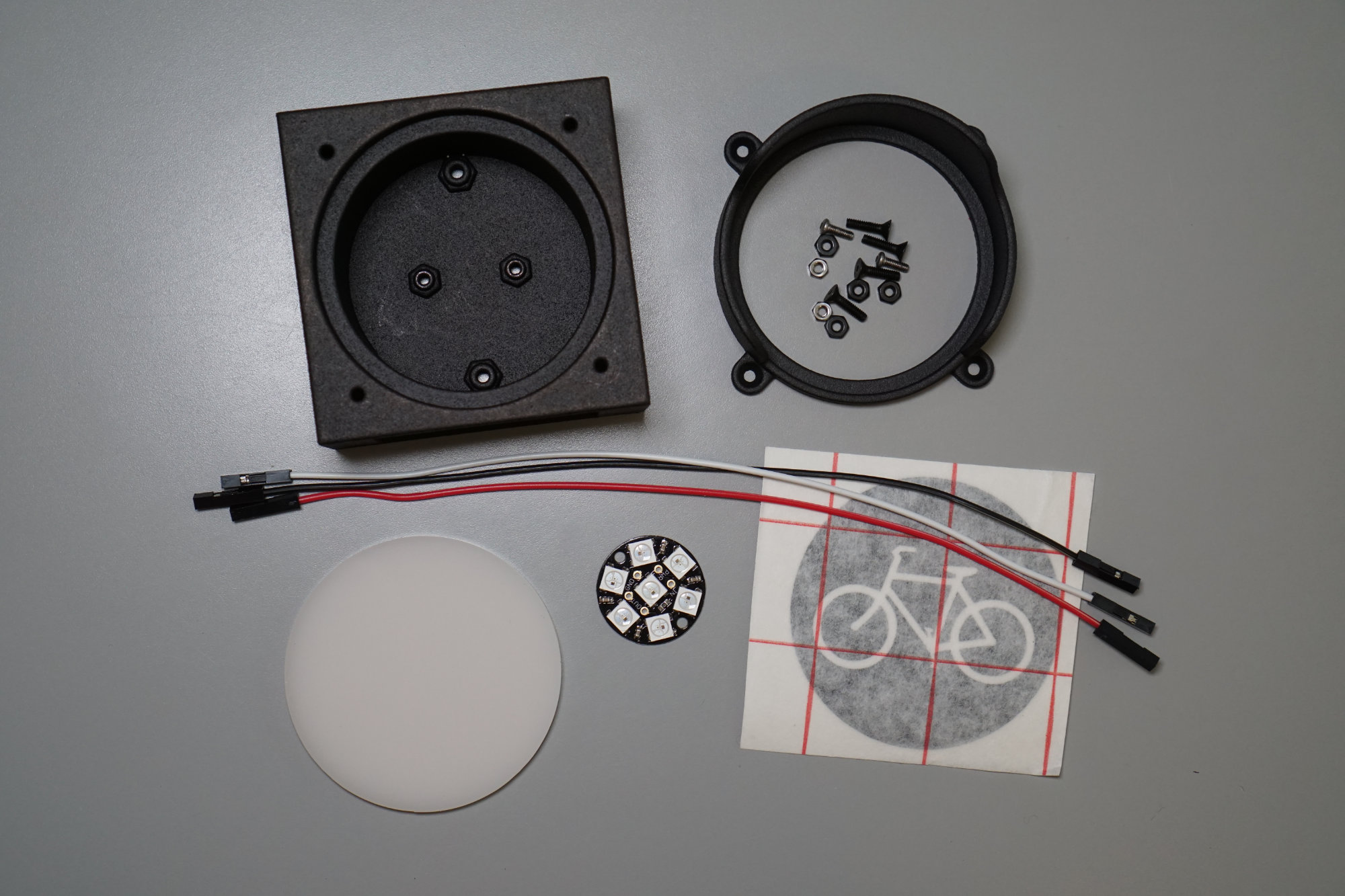
The parts required to build the Wi-Fi bicycle traffic signal.
The following parts are needed to assemble the bicycle traffic signal. Links to the files for 3d printing, laser cutting, and sticker making are located in the “Files” section at the end of this post.
- 3D printed traffic signal housing (1)
- 3D printed traffic signal hood (1)
- Laser cut acrylic traffic signal lens (1)
- Die cut bicycle or other symbol sticker (1)
- Adafruit Neopixel Jewel LED board (1)
- Adafruit jumper wires (3)
- 2-56 x 3/8″ black oxide hex drive flat head screw, McMaster-Carr Part #91253A079 (4)
- 2-56 black oxide hex nut, McMaster-Carr Part #96537A110 (4)
- M2-0.40 x 6mm hex drive button head screw, McMaster-Carr Part #92095A453 (2)
- M2-0.40 hex nut, McMaster-Carr Part #91828A111 (2)
- Particle Photon with Headers or Adafruit Feather M0 Wi-Fi (1)
- Double sided foam tape.
3D Printing the Housing and Hood
The housing and hood were designed in Autodesk Fusion 360. Links to both STEP and STL files for the housing and hood are provided in the “Files” section at the end of this post.
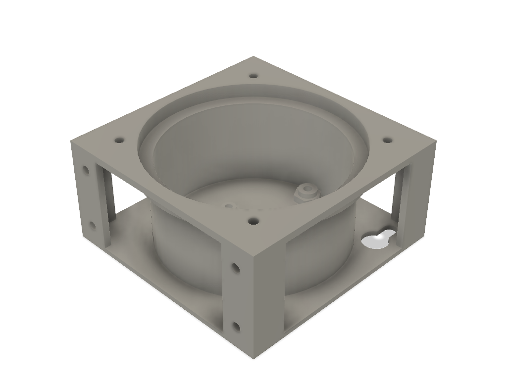
Traffic signal housing. The surface facing UP in this render should face DOWN in the print bed when printing using HP’s MultiJet Fusion printers.
The housing has provisions to hold an Adafruit Neopixel Jewel or a 2″ diameter custom LED board. I was worried the smaller Jewel board would cause the lens to have a hot spot in the middle of it but these fears were unfounded. The Neopixel’s viewing angle is wide enough that the light is sufficiently diffused to prevent a bright spot in the center of the lens. The housing also has cutouts for wall mounting on the back and holes for assembling multiple housing together into a multi-light signal.

Traffic signal hood. The surface facing UP in this render should face DOWN in the print bed when printing using HP’s MultiJet Fusion printers.
The hood screws to the front of the housing using 2-56 flat head screws and nuts and holds the acrylic lens in place. There’s a recess for each nut in the back surface of the housing. The original version of the hood had a smaller diameter but if you look at a real traffic light the hood extends almost all the way to the edges of the light so I made a new version of the hood with a slightly larger diameter.
I don’t own a 3D printer so I used Sculpteo’s 3D printing service to 3D print my housing and hood. Both the housing and hood were printed using HP’s MultiJet Fusion printers then dyed black using their color resist dye process. The housing costs about $30 to print and the hood costs about $14 to print.
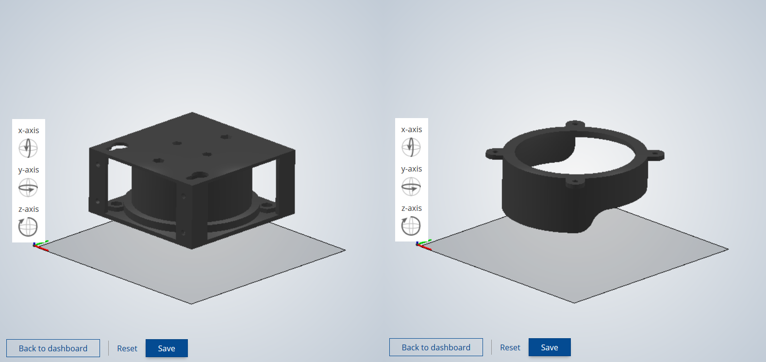
Illustration showing preferred orientation of housing and hood on the print bed when using HP MultiJet Fusion 3D printers.
When printing using the HP MultiJet Fusion printing process, the part needs to be oriented carefully in the printer. Best dimensional accuracy and mechanical properties are achieved in the planes parallel to the bottom of the print bed. Surfaces that are oriented downward are slightly softened and contain less grain in the finished surface while surfaces oriented upward are slightly sharpened and contain more grain in the finished surface.
For these two parts, the best results are obtained when the housing and hood are oriented down in the print bed. In other words, print with the surfaces that face the user toward the bottom of the printer as shown in the image above. This results in softer edges and a finer grain on the surfaces that are visible.
Laser Cutting the Lens
Guess what? I don’t own a laser cutter either. Fortunately, Sculpteo offers a laser cutting service. The DXF file for the lens is in the “Files” section at the end of this post. It’s just a 2.25″ diameter circle. Be sure to print the lens out of 1/8″ thick LED diffuse white acrylic. The cost was about $7 for one or $13 for five.
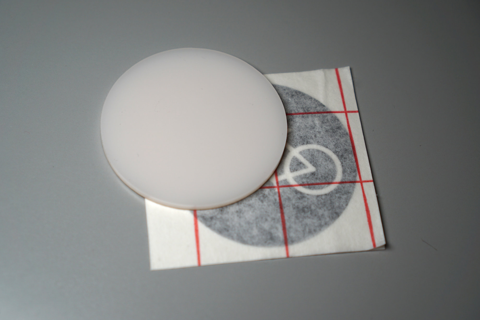
Acrylic lens and bicycle sticker ready to go!
Cutting the Sticker
I do own a vinyl sticker cutter! It’s a small Silhouette Cameo 3. It works well enough for the occasional sticker for my truck or labels for an enclosure or button or two. In this case, I used it to cut the bicycle sticker for the traffic signal lens.
The sticker is a 2.25″ circle with a 1.85″ wide bicycle cut into it. The bicycle artwork is from the PDF version of the Manual on Uniform Traffic Control Devices (MUTCD) Interim Approval for Optional Use of a Bicycle Signal Face (IA-16).
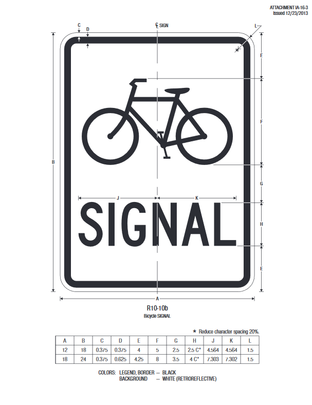
Do you like boring engineering specs drafted by huge committees and published by government agencies? Then you’ll LOVE the MUTCD. Here’s the official bicycle signal sign and the source artwork for the bicycle sticker.
I used an old copy of Illustrator to pull the bicycle artwork out of the IA-16 PDF and saved just the bicycle as an EPS file. I then used cloudconvert.com to convert the EPS to DXF. Once I had the DXF for the outline of the lens and the DXF for the bicycle, I was able to use the software that came with the vinyl cutter to merge the two together and cut a few stickers. The stickers are cut from Oracal 651 glossy black permanent adhesive vinyl, weeded, then transferred to the acrylic lens using transfer paper.
A DXF file containing a bicycle, an inner “viewable area” circle at 2″, and an outer “cut” circle at 2.25″ is included in the repository for reference in case you don’t have access to the Silhouette Cameo software or want to use a different cutter to make the sticker. If this is the case, you might want to make the bicycle a little bigger and delete the 2″ safe area circle before cutting. The bicycle on my stickers is 1.85″ wide.
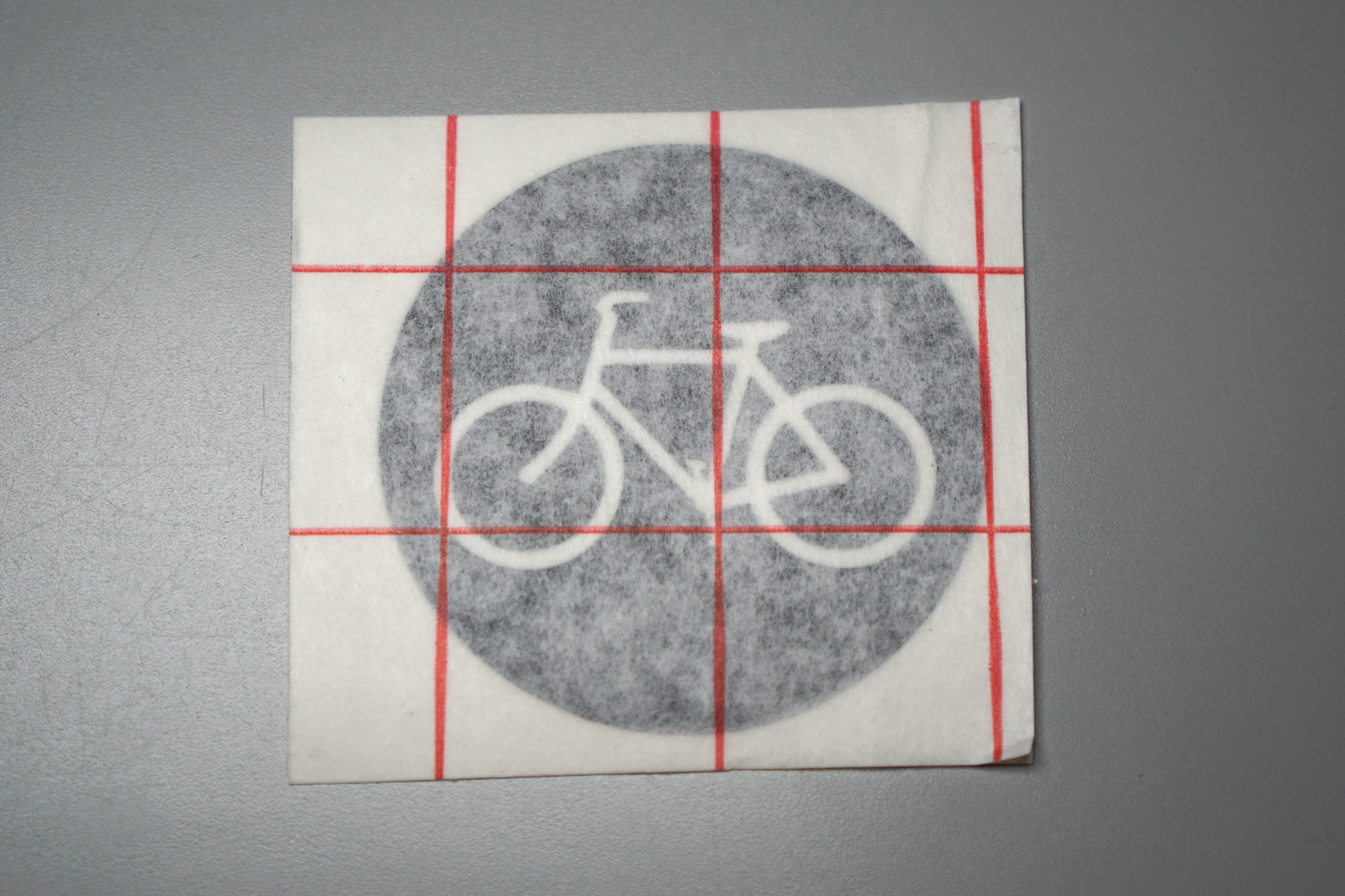
2.25″ diameter bicycle sticker cut out of vinyl, weeded, and ready to be transferred to the acrylic lens.
Assembling the Traffic Signal
1) Solder jumper wires to Neopixel Jewel.
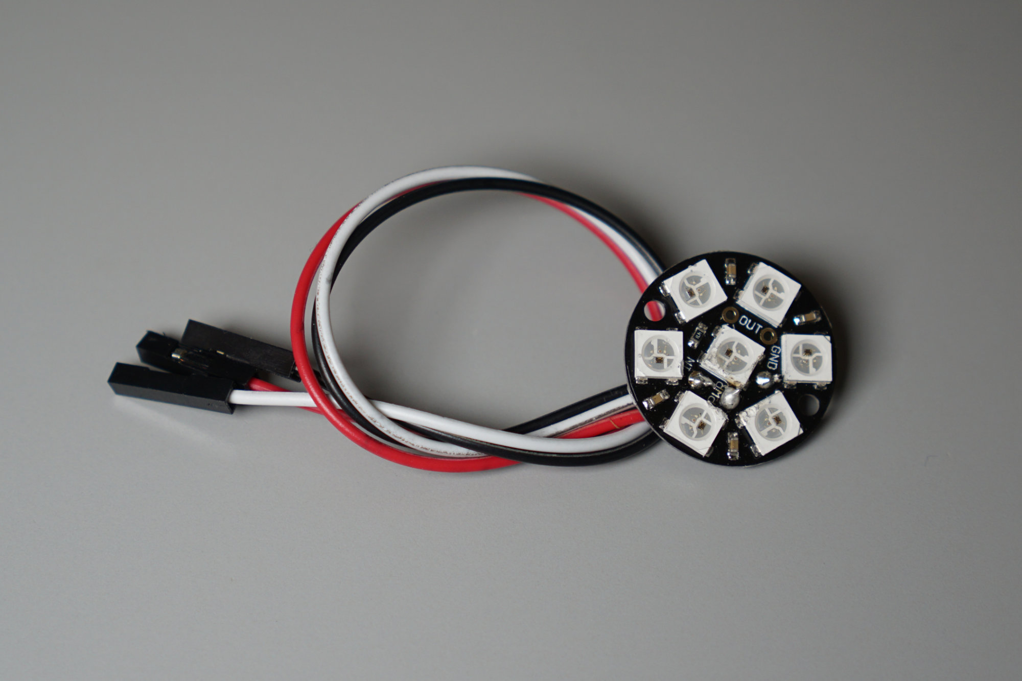
Not some of my best soldering work.
The first step is to solder the jumper wires to the Neopixel Jewel. Cut the housings off one end of the jumpers, strip a bit of insulation off, then feed the wires through the back of the Neopixel Jewel. It’s easiest to solder the wires only on the rear of the board. I soldered them on both sides and melted the WS2812b LEDs a bit on this board. Solder the red wire to the to PWR pad, the black wire to the GND pad, and the white wire to the IN pad.
2) Mount Neopixel Jewel to Traffic Signal Housing
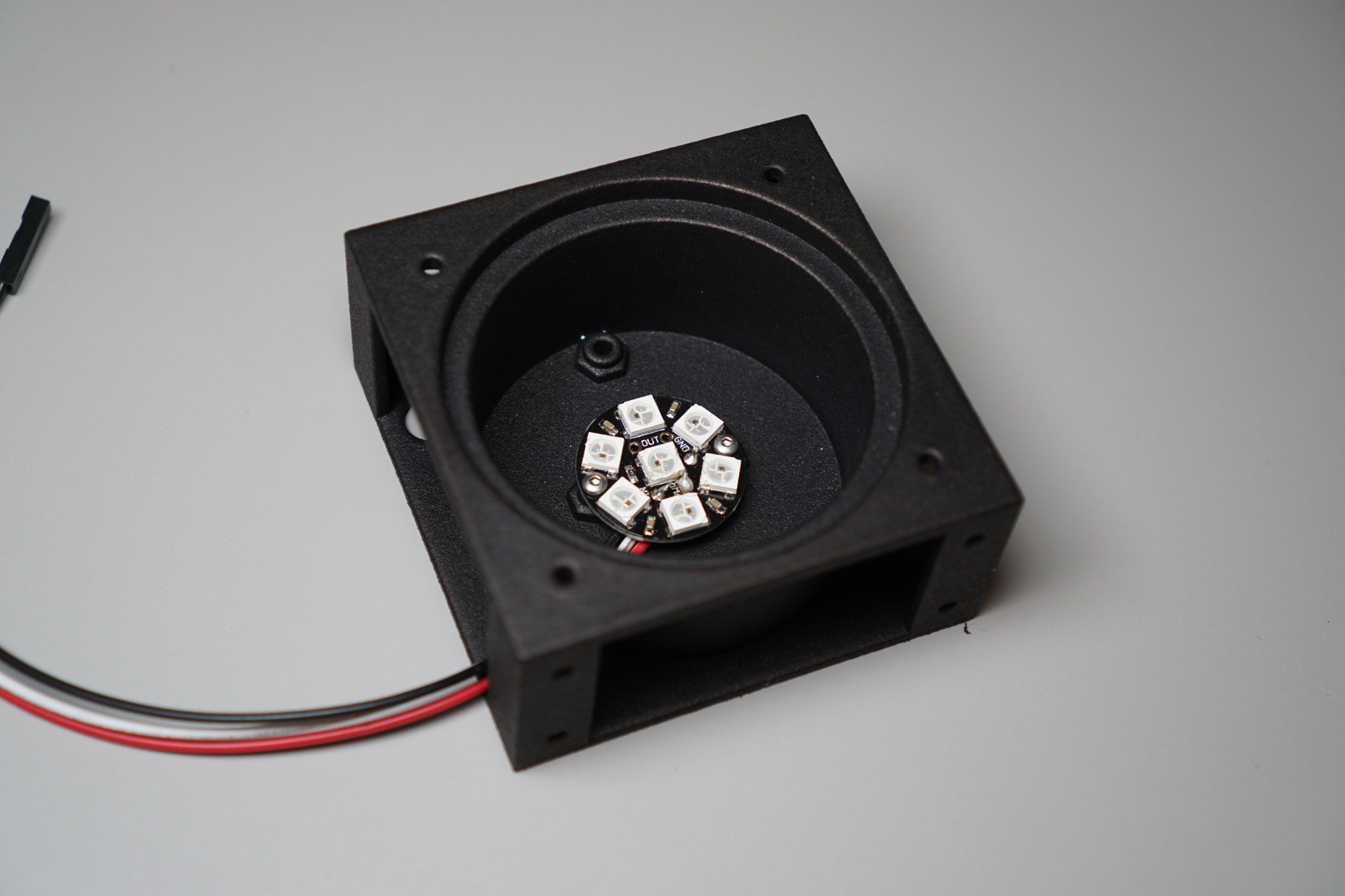
The Adafruit Neopixel Jewel mounted to the interior of the traffic signal housing.
The next step is to mount the Neopixel Jewel inside the traffic signal housing. There’s a cut out in the bottom left of the housing. Route the wires out through this cut out then mount the Neopixel Jewel using (2) M2-0.4 x 6mm screws. There are recesses on the rear of the housing to hold the M2-0.4 nuts.
3) Affix Bicycle Sticker to Acrylic Lens

Sticker affixed to lens.
Remove the protective paper from both sides of the acrylic lens and the release paper from the back of the bicycle sticker. Carefully position the sticker on the lens and apply firm even pressure to affix the sticker to the lens. Carefully remove the transfer paper from the lens and sticker.
It can be easier to align the sticker if you only remove a small amount of the release paper, cut off the removed paper, align and affix the exposed portion of the sticker, then remove the rest of the release paper and affix the rest of the sticker. Also to prevent air bubbles from getting trapped under the sticker, gradually lower the exposed portion of the sticker on to the lens, apply pressure from the center out to each edge, then lower the exposed sticker portion a bit more and repeat.
4) Insert Lens into Housing
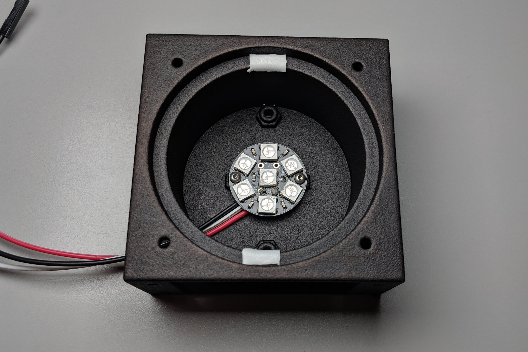
Some foam tape stuck inside the housing can prevent the lens from shifting and rattling.
The acrylic lens is slightly smaller and thinner than the cavity for it inside the housing. To prevent the lens from shifting and rattling inside the cavity, stick a bit of foam tape to the top and bottom of the lens opening like in the photo above. This will be completely out of view when assembled. You could also skip the foam tape. This will make the lens rotatable in case you want to show DH one day and wheelies the next. Align the lens and drop it into the housing’s cavity.
Getting close now!
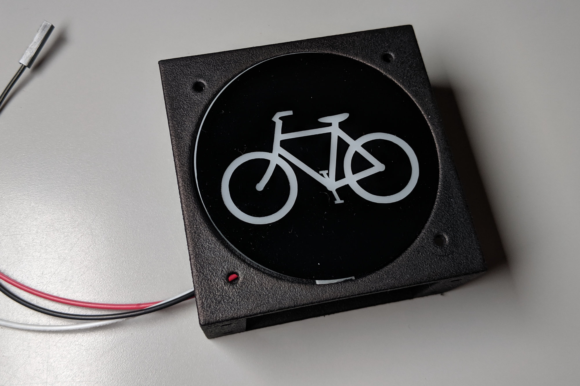
5) Mount Hood onto Housing

The bicycle traffic signal is now completely assembled!
The last step is to connect the hood to the housing. Use a 2-56 x 3/8″ black oxide flat head screw and 2-56 nut in each corner to secure the hood to the housing. On the back side of the housing is a recess to hold the 2-56 nut. Place the nut in the recess, hold it in place with your finger or another tool, insert a screw from the front, and tighten until secure.
Congratulations! Your bicycle traffic signal is now completely assembled and ready to be connected to a controller to light it up. In future posts in this series, see how to control the traffic signal over Wi-Fi using a Particle Photon or an Adafruit Feather M0 Wi-Fi board.
Design Files
The design files for this project are located in the mechanical directory of my bicycle traffic signal github repository.