
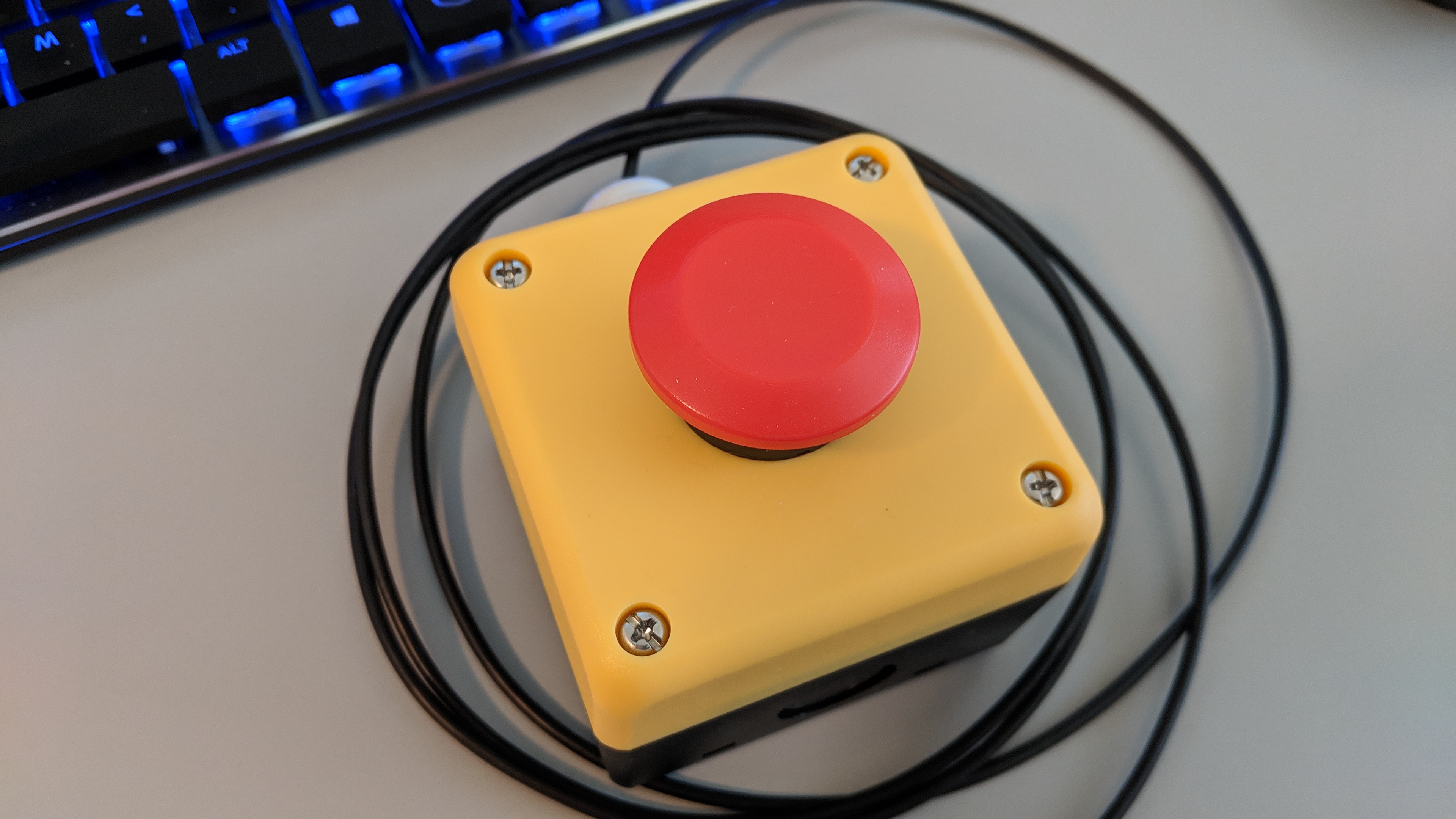
The completed USB-connected big red button.
In this project, I mount the electronics from my single-key USB keyboard project to the back of an industrial mushroom push button switch. The finished big red button now activates my screensaver with a single overly-large button press. The biggest issues in this project were where to mount the USB electronics and how to connect the USB cable between the button and my computer.
A Few Words About Industrial Controls
Industrial push buttons and indicators are the exact opposite of today’s sleek capacitive touchscreens. They’re tactile, bulky, single-purpose, take some force to operate, and are built to take abuse from both the environment and users. When a button fails after years of abuse, they’re modular to facilitate quick repairs and get whatever process they’re controlling back online quickly. (They do make industrial-rated touchscreen controllers if you really do need to have a touchscreen, e.g., to show / control process parameters.)
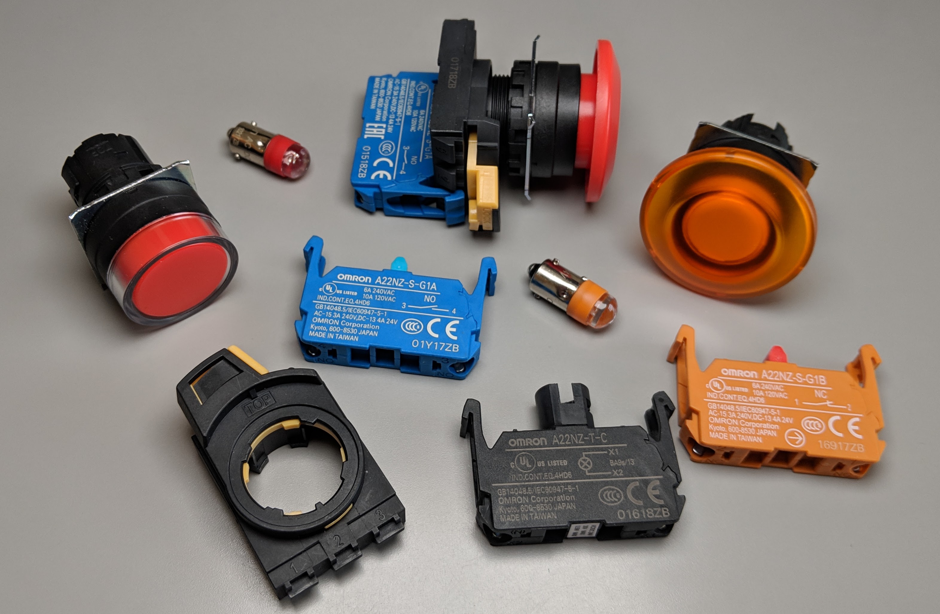
Random Omron switch parts including a shrouded red non-illuminated push button, illuminated mushroom button, a mounting collar, LEDs, NO contacts, illumination unit, NC contacts, and an assembled non-illuminated mushroom button.
In the photo above are a few disassembled Omron 22mm push button switches. The typical switch consists of an actuator, a mounting collar or frame, contact blocks, and, if illuminated, an illumination unit. The actuator is the part that mounts to the panel and is exposed to the user. These vary in shape and color often depending on if they’re designed to be easy to press (emergency power off) or hard to press (start self-destruct sequence).
The part immediately behind the actuator is a frame that connects the contact blocks to the actuator. The contact blocks do the electrical switching and are available in a variety of configurations such as normally open, normally closed, screw terminals, quick connect terminals, etc.
On these Omron controls, the contact blocks snap to the frame and a plunger on the actuator presses a plunger on the contact block to change the state of the contacts. In other designs, they mount using screws. Finally, if the switch is illuminated, there’s an illumination unit that can hold an LED or incandescent bulb. Below is a page from an Omron Industrial Automation catalog showing some of the available configurations and how they fit together.
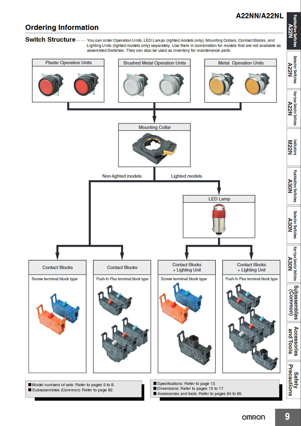
A page from the Omron industrial controls catalog.
By splitting the switch into so many pieces, the exact switch needed for a job can be built from its component parts. Also repairs can be performed quickly. For example if the actuator is broken, one can disconnect the frame, replace the actuator, reconnect the frame, and be back in business without any rewiring.
Where to Mount the Electronics
The immediate goals for this project were (1) to use a big red button and (2) to connect it to a computer using USB. Like any engineering project, there’s tons of ways to get to a solution and it’s my job to pick the optimum solution (where optimum is open to debate).
My first thought was to build a small box that had screw terminals for a contact closure input on one side and a USB connector on the other side. This box would sit between the big red button’s enclosure and the computer. A small circuit board would hold the USB electronics and I’d 3D print a case for it.
My second thought was to just let a loose circuit board float between the contact blocks inside the big red button’s enclosure. Things are pretty well insulated so it would be unlikely to short out. But I didn’t want this thing rattling inside my switch. Then it finally came to me, what if I could mount the electronics to the switch just like a contact block mounts to the switch?
Mechanical Design
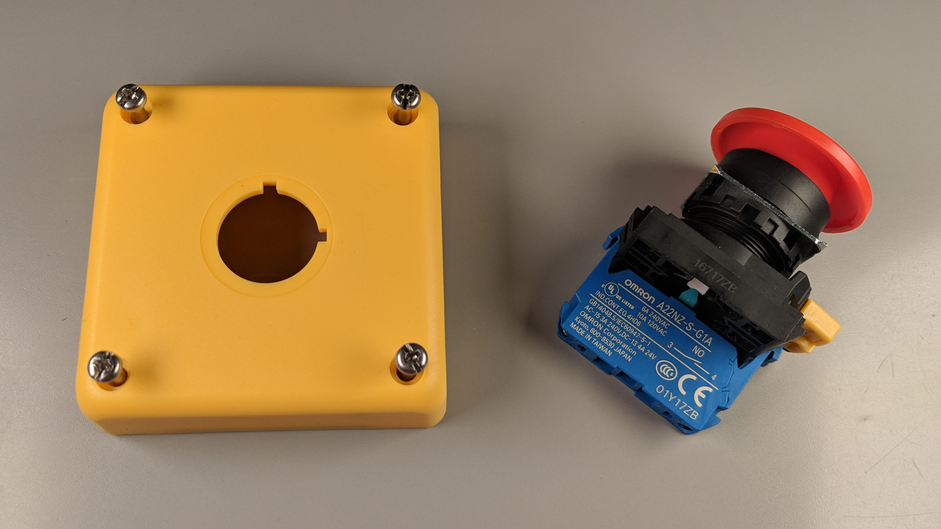
Raw materials. The lid of the enclosure and pushbutton switch with mushroom operator.
Omron Industrial Automation makes some relatively inexpensive industrial push buttons that are available from the usual distributors. They also make a nice bright yellow enclosure specifically for emergency stop / emergency power off / big red button mushroom switches. I went to Digi-Key and ordered an Omron A22NN-BMM-NRA-G100-NN mushroom switch for $10.97 and to Arrow and ordered an OmronA22NZ-A-B01Y single button enclosure for $12.74. These are shown in the photo above.
The stock Omron normally open contact block 3D model with a bit of additional color.
I needed a starting point for my PCB holder. Fortunately, Omron and most of the other industrial controls vendors publish 3D models of their devices. These models are primarily used during design of industrial control panels to make sure everything fits without interference. I downloaded Omron’s 3D model of their contact block, shown above, then used Fusion 360 to carve out an area to hold a small PCB. This most likely violates Omron’s terms of use for their models but since this is a one-off, personal, non-commercial project (aka a hack), I’m going to call it fair use and not lose any sleep over it.
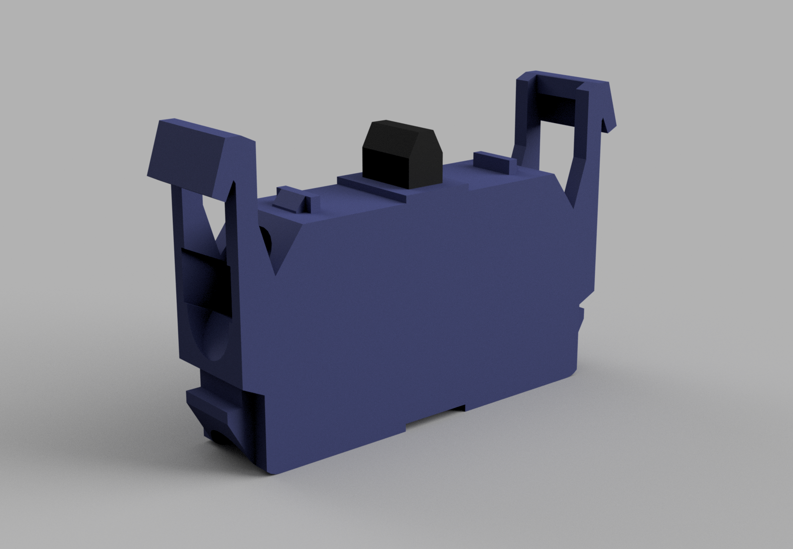
A render of the contact block circuit board holder and circuit board. Sometimes renders don’t work out in real life.
With a bit of work, I carved out an area to hold the circuit board, fit the board into the model, and added some tabs to hold the board in place without screws. Be sure to scrape off the switch plunger too otherwise you’ll end up with a fixed piece of plastic on top of the contact block frame that blocks the operation of the button.
Failure is good as long as you learn from it, right?
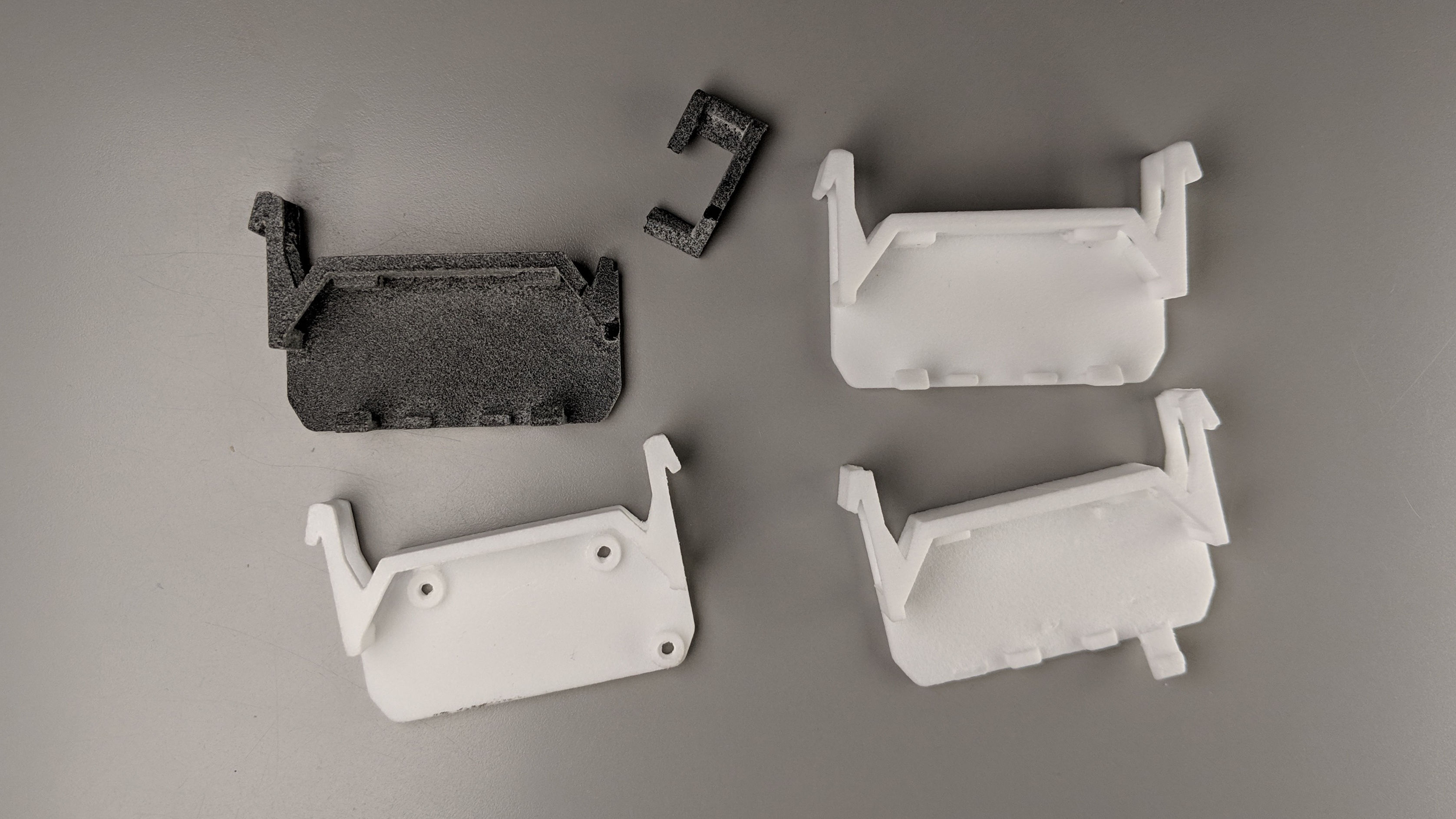
This design took a few iterations to get right. I printed the PCB holder in different materials at different 3D printing places. The SLS PA nylon process at Shapeways had different dimensions than the SLS PA nylon process at Sculpteo. The HP JetFusion process at Sculpteo had different dimensions than the SLS PA nylon process at Sculpteo. In addition, the HP JetFusion nylon is more brittle / less flexible than the SLS PA nylon. I finally got a print of a holder that would work in the SLS PA nylon process from Sculpteo.
Three failed boards and one good board. Fails: 1) screws rather than tabs. 2) header strip hits holder. 3) slots too small to accommodate tabs. Success: slots and header strip work!
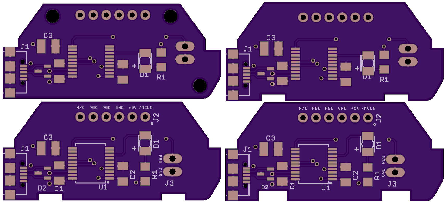
Unfortunately, I broke the tabs off the holder trying to fit the circuit board into the holder. Rather than redesign the holder, I redesigned the circuit board to have slightly bigger notches that wouldn’t stress the tabs as much during insertion. I went through a total of four revisions of the circuit board. The post office even lost two revisions of the boards for two weeks before finally finding them and delivering them.
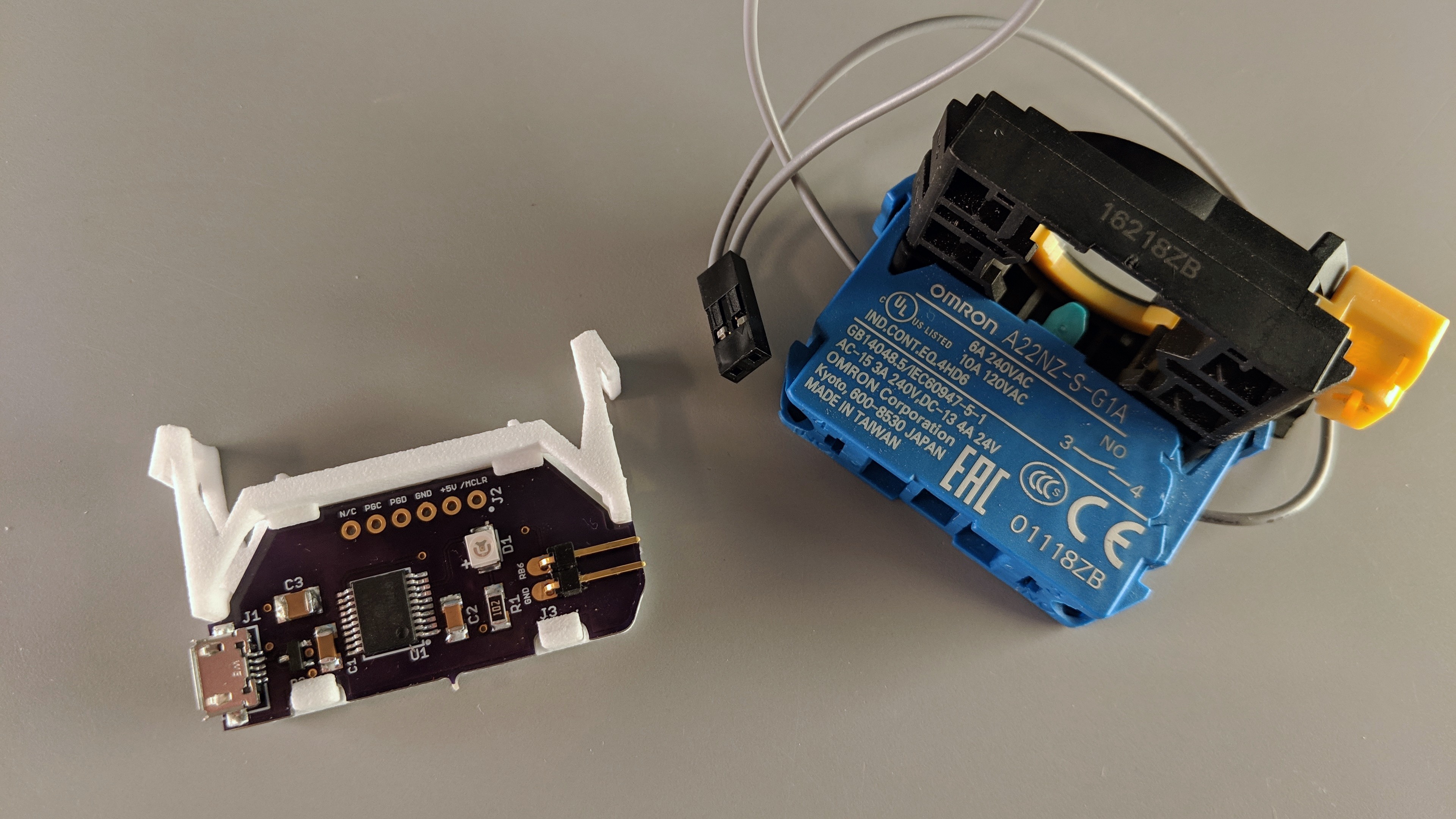
The finished circuit board and 3D printed holder next to the back parts of an Omron switch.
Success. After many more weeks and iterations than it should have taken, I finally got things right. With a bit of finesse and luck, I was able to place the finished circuit board into the 3D printed holder. I didn’t test the electronics before putting the board in the holder. Luckily, they did work.
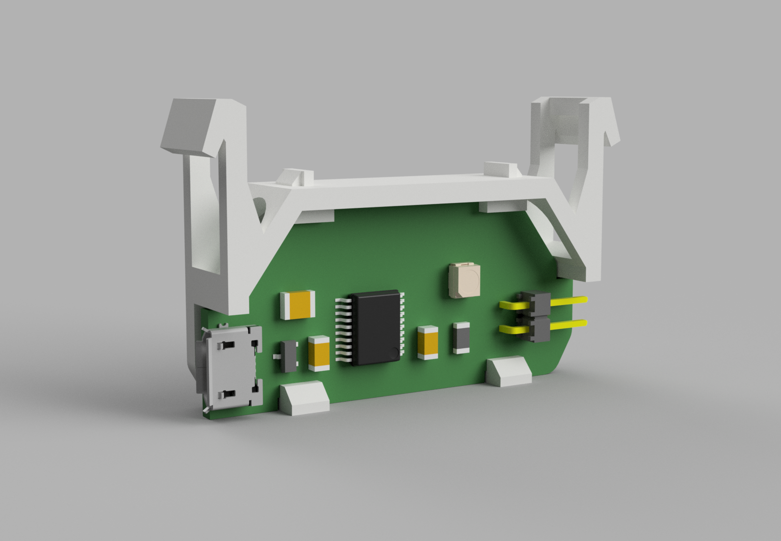
Finally, I did a bit of assembly in Fusion 360 to see if there was any hope of a USB cable mating with the USB connector on the PCB. I couldn’t get section analysis to work in the render view of Fusion 360 so I just lopped the bottom of the enclosure off for the render.
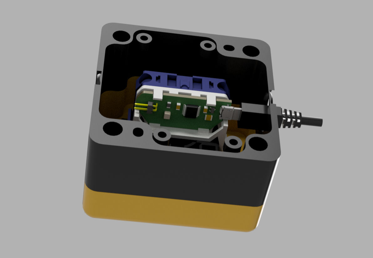
Will a USB cable connect to the board inside the enclosure? That’s a definite maybe.
Electrical Design
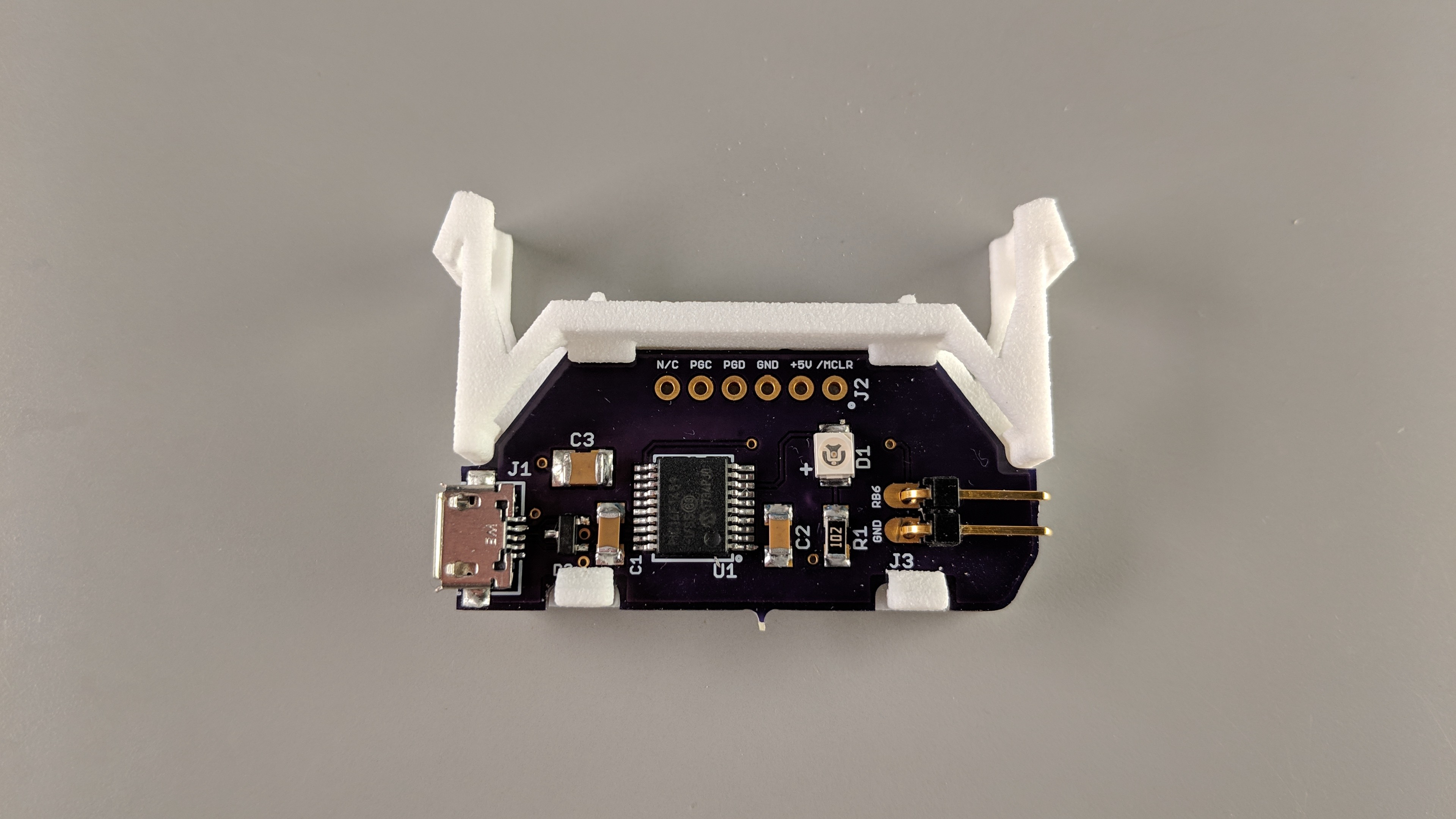
Board assembled into holder. I had access to isopropyl alcohol and lint-free cleaning swabs during assembly so the board is a bit cleaner than my usual boards.
The electrical design on this project was easy. It’s the same electronics as on the single-key USB keyboard project except I added a Texas Instruments TPD2E2U06QDBZRQ1 ESD protection device to the USB data lines and replaced the Cherry MX keyboard switch with a two pin 0.1″ right angle header. Next time I might try a Nexperia PRTR5V0U2X that can protect both the USB power line and USB data lines.
Software Design
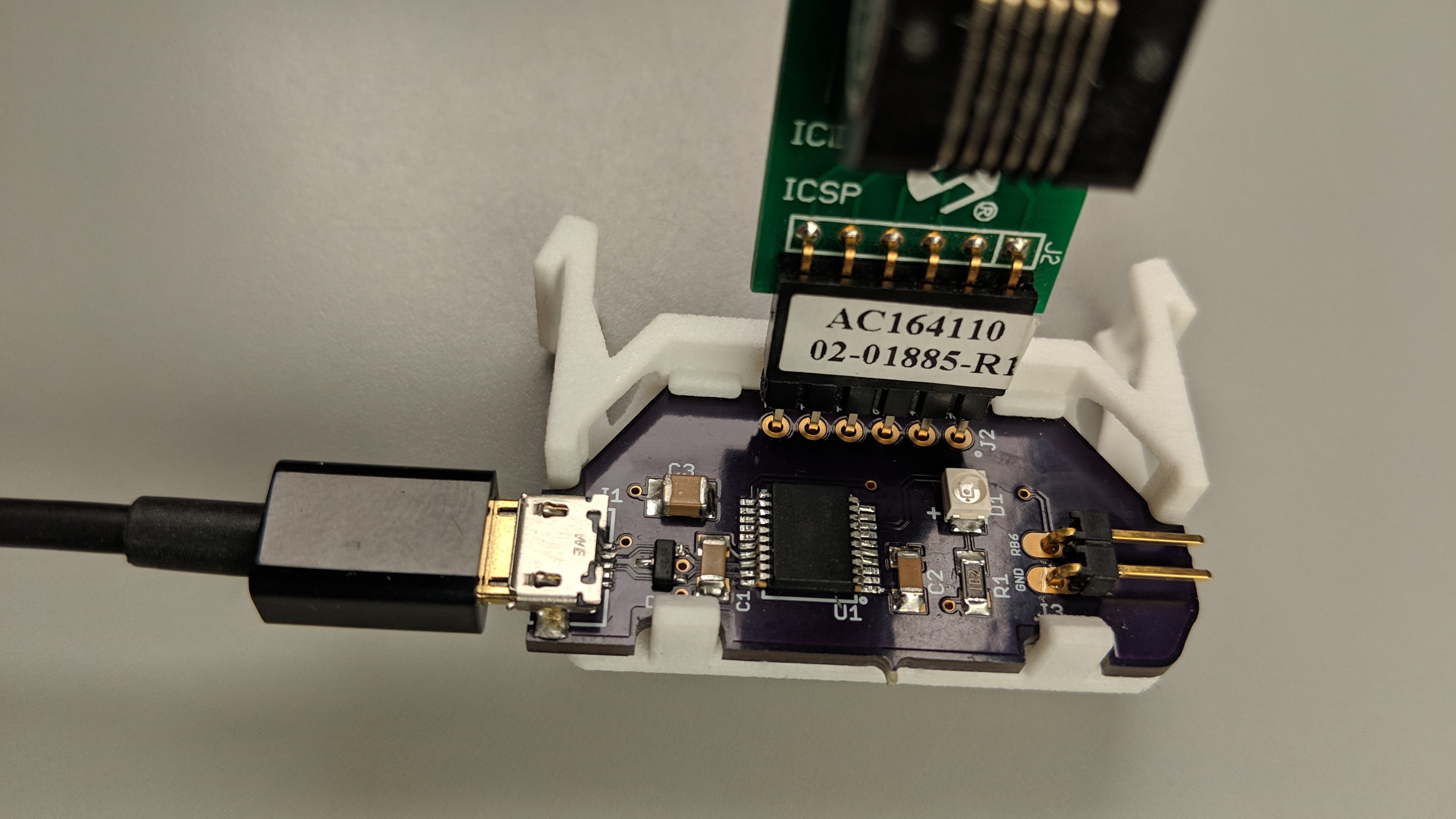
Programming the bootloader is a bit of a pain but thankfully it only has to be done once.
The software is divided into two parts, a bootloader and the application software. These are the same as on the single-key USB keyboard project too. The USB bootloader is programmed into the part using any PIC programmer such as a REAL ICE or MPLAB ICD 4. It’s a bit awkward holding the programmer adapter on the board as shown in the photo above but it only has to be done once. The bootloader then enables the application software to be updated over USB without disassembling the completed project.
Once the bootloader is programmed, the application software may be updated by holding down the big red button while connecting the USB cable to the computer. This action enables the bootloader then the bootloader utility from the Microchip Libaries for Applications may be run to load new application software onto the PIC16F1459.
Currently I have two versions of the application software. One inserts a poop emoji into Microsoft documents. The other hits right-ctrl to escape Oracle’s VirtualBox’s keyboard capture then left-ctrl & left-alt & l to invoke the RHEL screensaver / screen lock on my Linux box at work.
Final Touches
Now the only thing left to do was to assemble everything. It took a bit of finesse to get the board mounted into the holder without breaking anything.
Board assembled into holder.
Next was a dry fit test of the assembled push button.
Yep, everything fits!
I used some jumper wires with a two position 0.1″ socket header attached to connect the contact block to the circuit board.
The finished circuit board and 3D printed holder next to the back parts of an Omron switch.
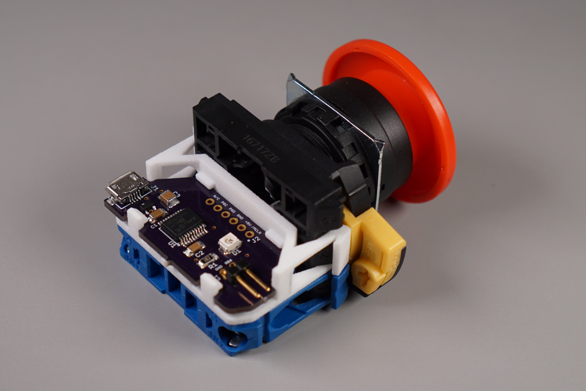
Then I snapped the contact block and holder into place on the switch frame and mounted the switch frame to the actuator. Sliding the little yellow lever below the USB cable locks the frame to the actuator.

Here’s a view with everything assembled and mounted to the top half of the enclosure.
And voila! The finished project!
The completed USB-connected big red button.
Design Files
If you’re interested in the mechanical design files for the project, let me know via Twitter and I’ll post them to github. In the meantime, check out the software and schematic for my single-key keyboards on github.
An Important Safety Note
As fun as this project may have been, please do NOT use USB for an actual safety-related emergency stop or emergency power off. USB is just not reliable enough for safety-related devices.