
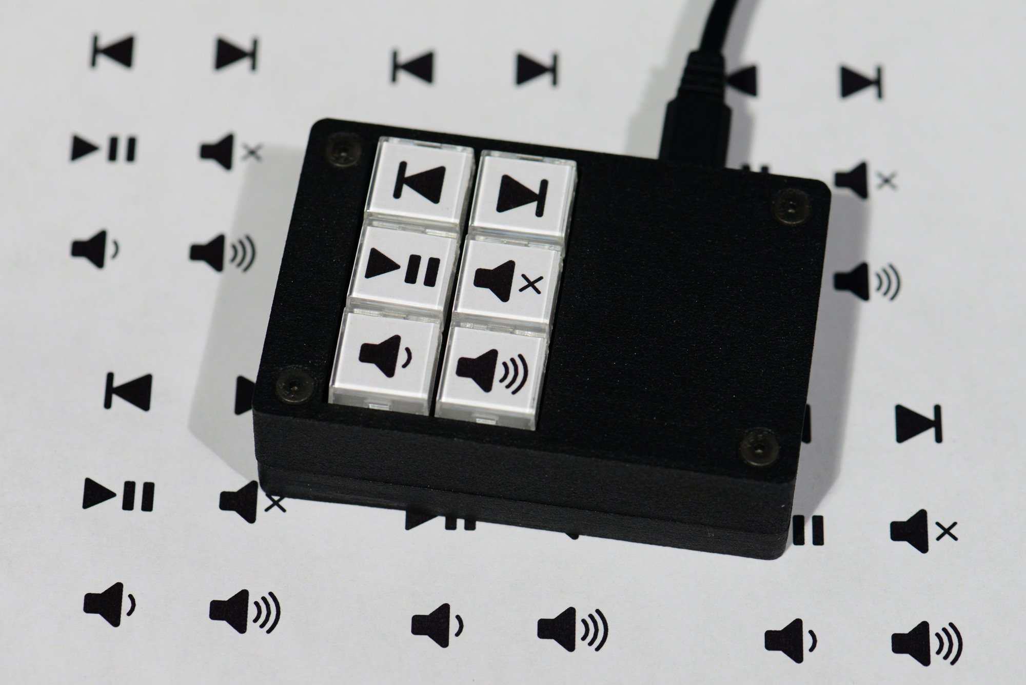
The finished wireless remote control for my Mopidy music server. Playback control and volume Icons by Icons by Darrin Loeliger (@MrNumma) and the Noun Project.
After wiring the house for a Dante digital audio network and building the Spotify and Pandora Wireless Remote Track / Artist / Album Display project, I decided the next thing needed to fix up my music listening experience was a quick way to change tracks, control playback, and adjust the volume without messing with a phone or web browser. The Wi-Fi connected Mopidy music server remote control was born!
Project Overview
This box uses a Particle Photon and six NKK UB2 series push button switches in a 3D printed enclosure to control a Mopidy music server running on an Intel NUC running Ubuntu Linux in my basement. I originally built this hardware several years ago to control some Hunter Douglas motorized window shades with an astronomical clock. The shades would close during the heat of the day to keep the house cooler and prevent fading the photographs hanging on the walls. I built two of these boxes at the time and the second one has sat unused ever since. It has Wi-Fi connectivity and six buttons and would be perfect for controlling the Mopidy music server.
Related Projects
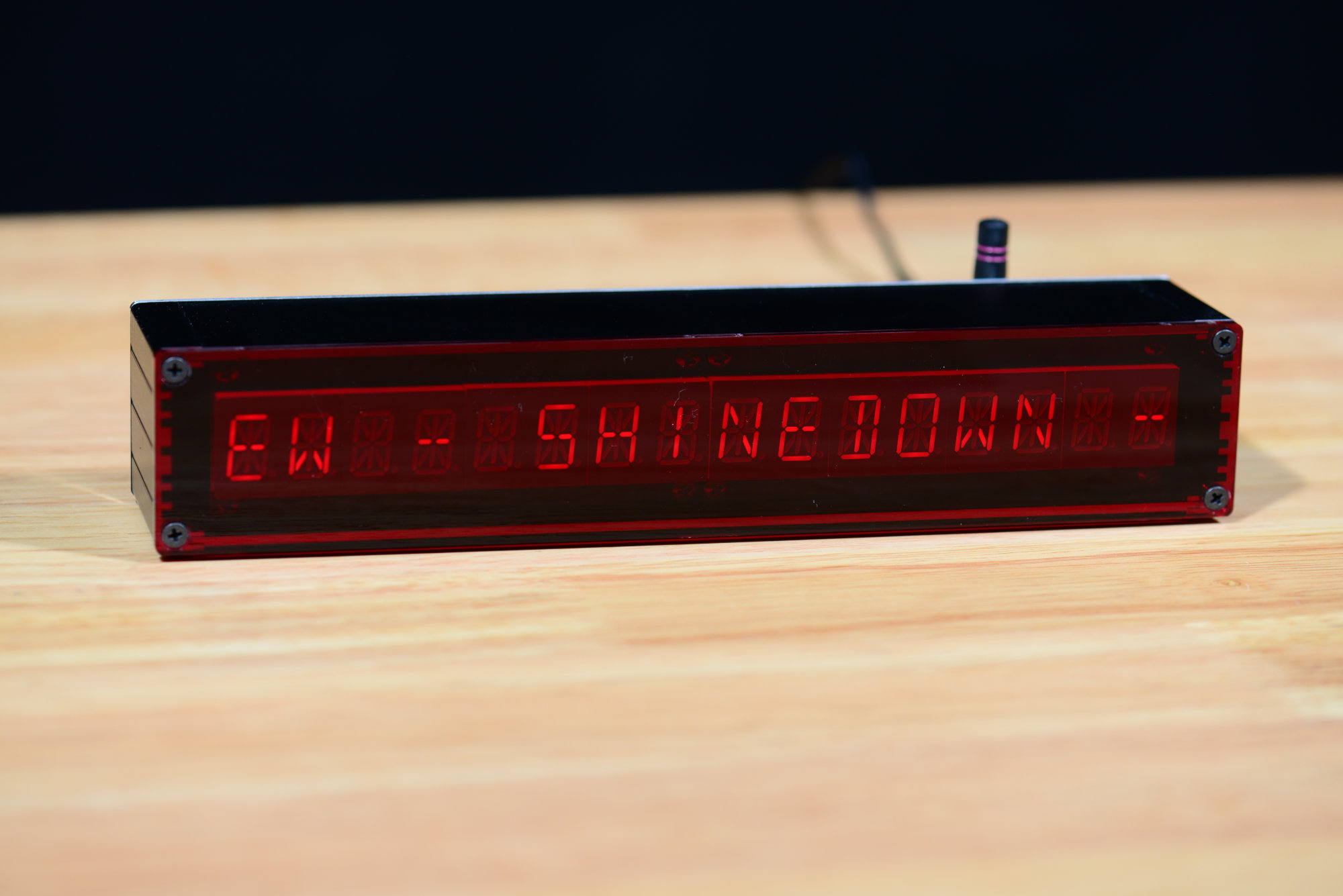
The completed music server remote track/artist/album display.
This project is a follow-on project to my Spotify and Pandora Wireless Remote Track / Artist / Album Display project. Both of these projects incorporate a Particle Photon because of its easy-to-use Wi-Fi networking capabilities. Both of these projects also connect to the web server built into Mopidy for monitoring and controlling music playback.
In the case of the remote display, the display connects to Mopidy’s WebSockets events URL. The WebSockets URL keeps a single connection open between the display and server all the time. The Mopidy server then pushes event messages to the display using this connection. These event messages can, for example, indicates the start of a track, changes in the playback state, or changes in the volume level. When an event message is received, the display is updated.
In the case of the remote control, the display connects to Mopidy’s remote procedure call (RPC) URL. The RPC call, in contrast to the WebSockets event interface, uses ordinary single-use HTTP requests and responses. The remote connects to the music server, sends a command to advance to the next rack, and then disconnects from the server.
Wireless Controller Board
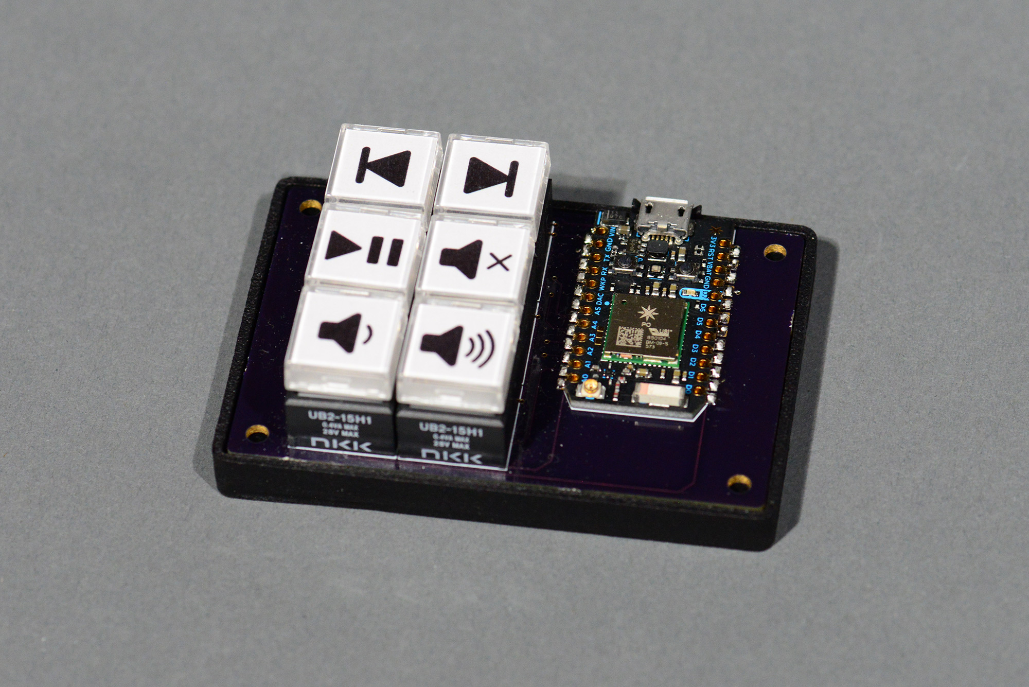
The controller board. The headerless version of the Particle Photon is soldered directly to the control board.
The wireless controller board consists of a Particle Photon and six NKK UB2 series amber illuminated push buttons with square, flat caps.
Schematic

Schematic
The schematic is shown in the image above. The Particle Photon is connected to the six push buttons. The A0-A5 pins are connected to the push buttons and the D0 to D5 pins control the amber LEDs in each button.
Each push button is connected to the Photon with a 1 kohm pull-up resistor to +3.3V. This keeps a logic ‘1’ on the input when the button is not pressed. When the button is pressed, the input pin is grounded and presents a logic ‘0’ to the Photon and software.
The LEDs are powered from +5V through a 330 ohm current limiting resistor. Each LED is connected to an NPN transistor switch. The base of the NPN transistor is connected to a digital output pin from the Photon. When the Photon drives a ‘0’ on its output, the transistor switch is turned off and the LED is not illuminated. When the Photon drives a ‘1’ on its output, the transistor turns on and conducts current from the +5 V rail, through the current limiting resistor, and through the LED thus illuminating the LED.
The LEDs are powered from +5 V rather than +3.3 V because the Photon’s +3.3 V regulator is limited in the amount of power it can provide safely. The +5 V from the USB bus is limited to 1 amp. The LED’s draw no more than 120 mA which is safely within the USB bus spec including the power consumed by the Photon.
Board Layout
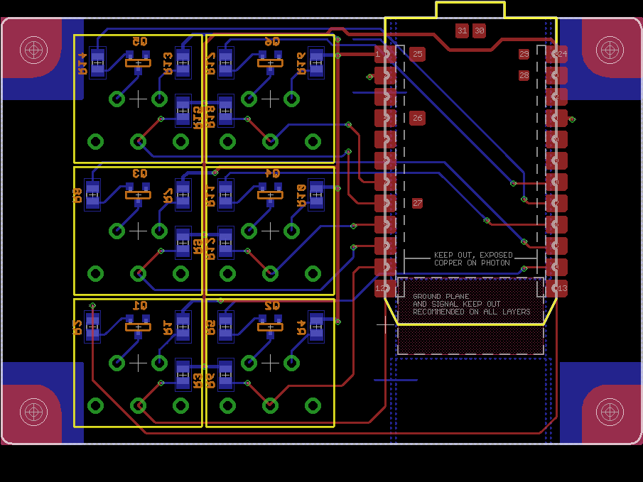
Board layout
The board layout is shown in the image above. The Particle Photon is the headerless version and is soldered directly to the top of the circuit board. The push button switches are located on the top of the board too. The transistors and passive components are soldered to the bottom of the board.
Four screw holes are located in each corner of the board. These holes align with the screw holes on the enclosure. Keep out areas in the corners correspond to the location of the standoffs built into the enclosure. The bottom keep outs are larger to accommodate the hex nuts located on the bottom of the enclosure.
Software
The software runs on the Particle Photon. It’s built using the Particle online IDE located at build.particle.io. This build environment supports over the air updating of the software running on the Photon. This is convenient because I can update the Photon software without needing to connect the remote to a computer with USB and without needing to take the remote apart.
After initializing everything and connecting to Wi-Fi and the Particle Cloud, the software sits in a loop that debounces the six push buttons. When a button is pressed, a function corresponding to that button’s function is called. These functions can be roughly grouped into track playback controls, play/pause, mute/unmute, and volume adjustments.
Track Playback Controls
The track playback controls are the easiest to implement. These require sending a JSON-formatted message to the RPC URL of the Mopidy server using an ordinary HTTP request. Here’s the JSON-formatted message to skip back a track:
{"jsonrpc": "2.0", "id": 1, "method": "core.playback.previous"}
Here’s the JSON-formatted message to skip forward a track:
{"jsonrpc": "2.0", "id": 1, "method": "core.playback.next"}
Play / Pause Control
The play / pause controls are slightly more difficult to implement. There is not a command to play or pause the server. Instead there is a command to play the server and a command to pause the server. To determine which command to send, the current playback state of the server needs to be queried using the following JSON-formatted query:
{"jsonrpc": "2.0", "id": 1, "method": "core.playback.get_state"}
The server will replay with the following if the server is currently in the play state:
{"jsonrpc": "2.0", "id": 1, "result": "playing"}
Or the following if the server is currently in the pause state:
{"jsonrpc": "2.0", "id": 1, "result": "paused"}
Depending on the received state, the remote control makes a request to pause playback:
{"jsonrpc": "2.0", "id": 1, "method": "core.playback.pause"}
Or to start playback:
{"jsonrpc": "2.0", "id": 1, "method": "core.playback.resume"}
Mute / Unmute Control
Mute and unmute work similarly to play and pause. First query the current mute state:
{"jsonrpc": "2.0", "id": 1, "method": "core.mixer.get_mute"}
The server replies with one of these two responses:
{"jsonrpc": "2.0", "id": 1, "result": false}
or
{"jsonrpc": "2.0", "id": 1, "result": true}
Then the remote sends one of these two commands:
{"jsonrpc": "2.0", "id": 1, "method": "core.mixer.set_mute", "params": {"mute": true}}
or
{"jsonrpc": "2.0", "id": 1, "method": "core.mixer.set_mute", "params": {"mute": false}}
Volume Control
To control the volume, the remote makes an HTTP request to the Mopidy music server to query the current volume level:
{"jsonrpc": "2.0", "id": 1, "method": "core.mixer.get_volume"}
The HTTP response will respond with something similar to the following:
{"jsonrpc": "2.0", "id": 1, "result": 100}
Then the remote control makes another HTTP request with the new volume level:
{"jsonrpc": "2.0", "id": 1, "method": "core.mixer.set_volume", "params": {"volume": 95}}
Enclosure Design
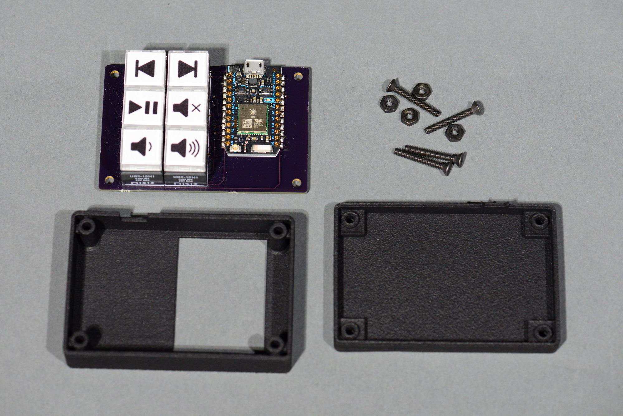
All the parts required to finish the project.
The enclosure was designed in Autodesk Fusion 360 and 3D printed at Sculpteo using HP’s Multi Jet Fusion 3D printing process. The enclosure screws together using some black oxide screws and nuts. The heads of the screws are countersunk into the top of the enclosure. The hex nuts fit in hex cutouts on the bottom of the enclosure.
The board rests on top of a set of standoffs designed into the bottom of the enclosure. A second set of standoffs built into the top of the enclosure hold the board in place when assembled. The screws thread through the standoffs and the holes in the corners of the board.
Key Labels

The page of labels in the cutter software. Red lines are cut. Black images are printed.
I designed and cut the labels for the push button switches in Silhouette Studio 3 using a Silhouette Cameo 3 vinyl cutter. The icons were designed by Darrin Loeliger (@MrNumma on Twitter) and can be downloaded from The Noun Project.
The NKK UB2 series data sheet lists the dimensions of the key labels. I drew these as red squares. I then pasted the icons into the Studio 3 document and sized them to fit inside the red squares. I turned on registration marks in Studio 3 then set it to cut on the red lines and print the black object. I printed the labels out on an ordinary sheet of 8.5″ x 11″ copy paper on a laser printer.

Cutting the key labels using a consumer grade vinyl cutter.
I placed the sheet of icons on sticky Silhouette vinyl cutter mat and loaded it into the vinyl cutter. I set the cutter for copy paper and hit the cut button. The cutter scans the registration marks in the corners of the pages the aligns the cuts to those registration marks. It’s a pretty clever system. I pried the little square labels off the cutting mat with a knife then proceeded to place them in the key caps for the switches.

Key labels and key caps for a similar switch. This switch is an RGB illuminated version by E-Switch. The E-Switch caps are slightly smaller than on the NKK switches. After cutting the attitude adjustment label, I used a pair of scissors to trim it down to size and, hence, it’s not as square as the real labels on the music remote control.
After printing and cutting the key labels and peeling the off the cutting mat, I carefully pried the clear cap off each key and inserted the corresponding key label. I repeated this six times for each of the keys, replaced the keys on their switches, and finished the project!
Design Files
The design files for this project are in remote-control directory inside the music-server-remotes repository in my Github account.