
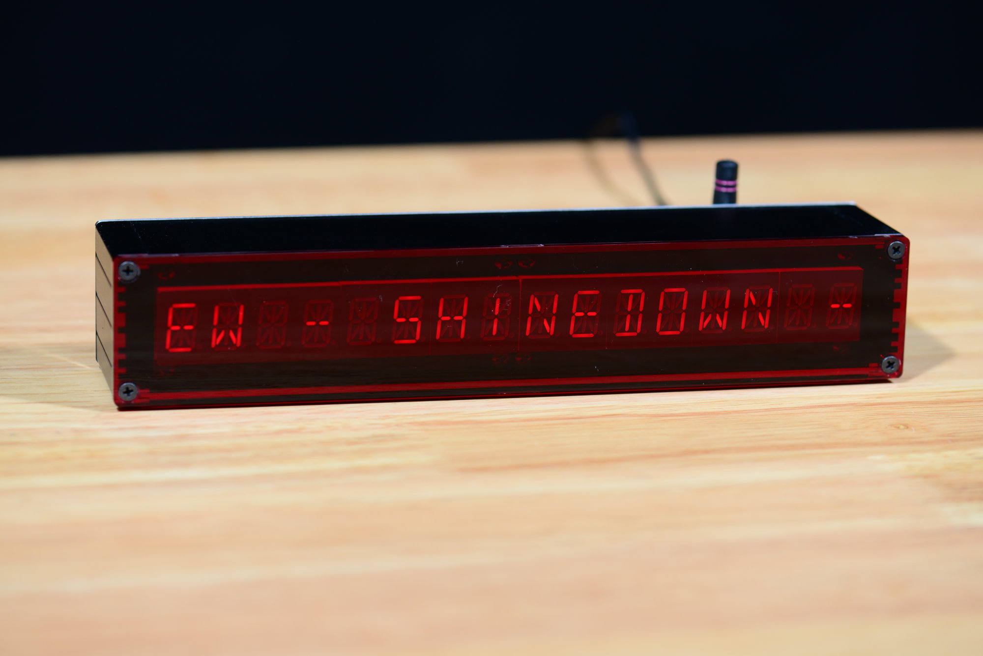
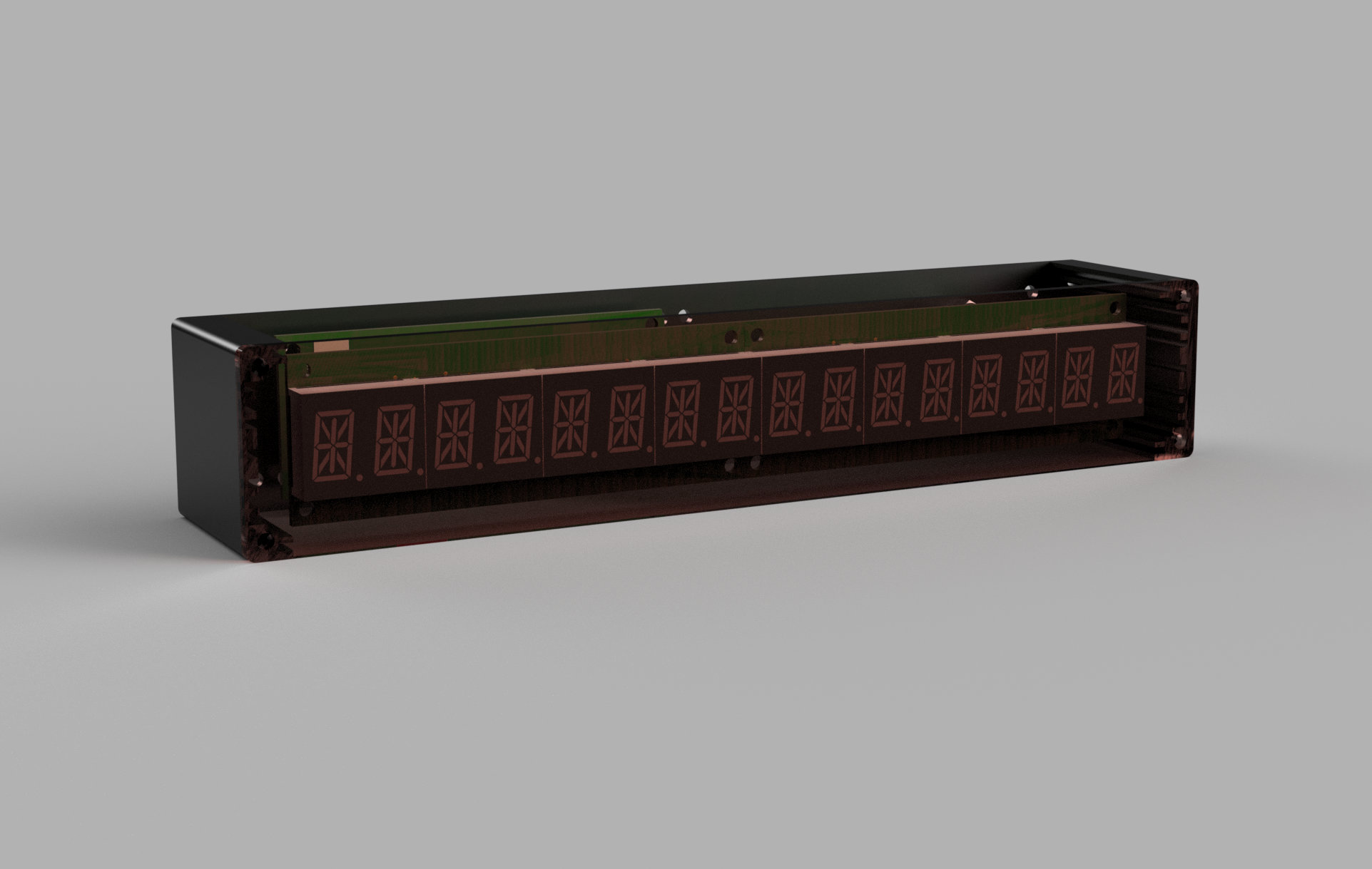
The completed music server remote track/artist/album display.
I use Pandora and Spotify a lot–typically from 7 in the morning until 11 at night. I got frustrated with the Spotify and Pandora apps on my Pixel 2 and their inability to find and control my Chromecast Audio players reliably. I also wanted a quick way to identify new songs or artists I heard without having to find my phone and open an app.
To solve these problems, I moved my music playing ecosystem to Linux and installed a wired Dante digital audio network for audio distribution. Finally I built a retro 14-segment, scrolling, always-on LED display that I could quickly glance at to discover what song was playing without having to find my phone and open an app.
Project Overview
This project has a lot of pieces. Mopidy and Pianobar are used to play Spotify and Pandora under Linux. Audionate Dante audio input and output adapters are used to distribute digital audio over Ethernet throughout my home. The display itself contains two LED display boards and a controller board. A Particle Photon on the controller board connects wirelessly to two different websockets servers to get the music data to display. Finally, there’s the enclosure to hold all the display parts.
Linux Music Server Software
This project uses Mopidy to play tracks from my local music collection and from Spotify. It uses Pianobar to play my Pandora stations. The installation of either of these packages and all their parts is beyond the scope of this post. Instead, I’m going to focus on the features of the software that allow them to communicate with other hardware and software.
Mopidy
The Iris frontend for the Mopidy music server.
Mopidy is a headless audio player daemon that can run in the background on common Linux distributions such as Ubuntu. Mopidy can be controlled on phones, in a web browser, or from the command line using various 3rd party add-ons. I use Iris in a web browser to control Mopidy on my computer and Mopidy Mobile to control Mopidy from my phone.
Both of these frontend clients get their status information from Mopidy and control Mopidy using a websockets server built into Mopidy. After a client connects to the websockets server, the server will send state change information like play, stop, volume, or track changes to the connected clients. A client can also send commands like previous track, next track, or volume changes to Mopidy using the same websockets connection. When a client changes the player state, the state change is communicated to all connected clients over their websockets connections.
You can connect to the Mopidy websockets server using curl as follows:
curl --include --no-buffer --header "Connection: Upgrade" --header "Upgrade: websocket" --header "Host: 192.168.180.8:6680" --header "Sec-WebSocket-Key: SGVsbG8sIHdvcmxkIQ==" --header "Sec-WebSocket-Version: 13" http://<YOUR_MOPIDY_SERVER_IP_ADDRESS>:6680/mopidy/ws
Once connected, you can play around with the track and volume controls in Iris and see the JSON formatted messages that are sent to clients with the information about player state changes. Here’s are a few examples where I adjusted the volume slider in Iris:
{"volume": 48, "event": "volume_changed"}
{"volume": 56, "event": "volume_changed"}
{"volume": 100, "event": "volume_changed"}
My wireless remote track / artist / album display connects to this websockets server. When the player state changes, the display receives these JSON-formatted message from the server and updates the displayed information. We’ll get into the details of the websockets client and the display software in a later section in this post.
Pianobar
The Pianobar user interface. It’s rather boring. As it should be.
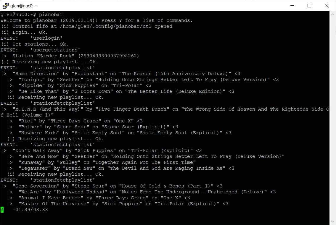
Pianobar is a command line tool for playing Pandora stations on Linux. There are a few web browser and mobile phone app frontends for the player but I just use the command line. Pianobar supports using a Linux FIFO to feed playback control commands into the player from 3rd party clients. Pianobar can also execute a Linux command whenever a state change event occurs. The FIFO and state change command interfaces are much simpler and much less comprehensive than those provided by Mopidy.
To drive my display, I use Pianobar’s event command interface to execute some C code that relays new track information to a very simple server running in node.js. This server has a simple HTTP web server for receiving track information from the C code and a websockets server that in turn relays the received track information to any connected clients.
The C code is pretty simple:
#include <stdio.h>
#include <stdlib.h>
#include <stdint.h>
#include <unistd.h>
#include <string>
#include <cstring>
#include <iostream>
#include <curl/curl.h>

#define URL "http://<MYSERVERIP>:6682"

void escape_quotes (std::string& data);
void curl_simple_post (std::string url, std::string& json);

int main (int argc, char *argv[])
{
    if (argc >= 2) {

        char *event = argv[1];

        if (!strcmp (event, "songstart")) {

            // printf ("EVENT:    SONGSTART\n");

            std::string input;
            std::string title = "";
            std::string artist = "";
            std::string album = "";

            while (!std::cin.eof ()) {
                size_t pos;

                // get a line of input
                std::getline (std::cin, input);
                // printf ("The input was '%s'\n", input.c_str ());

                // try to find a title
                pos = input.find ("title=");
                if (pos != std::string::npos) {
                    title = input.substr (pos + 6, std::string::npos);
                }

                pos = input.find ("artist=");
                if (pos != std::string::npos) {
                    artist = input.substr (pos + 7, std::string::npos);
                }

                pos = input.find ("album=");
                if (pos != std::string::npos) {
                    album = input.substr (pos + 6, std::string::npos);
                }
            }

            escape_quotes (title);
            escape_quotes (artist);
            escape_quotes (album);

            // printf ("  TITLE:    '%s'\n", title.c_str());
            // printf ("  ARTIST:   '%s'\n", artist.c_str());
            // printf ("  ALBUM:    '%s'\n", album.c_str());

            std::string json = "{ event: \"songstart\", title: \"" + title + "\", " +
                "artist: \"" + artist + "\", " + "album: \"" + album + "\" }";

            // printf ("  JSON:     '%s'\n", json.c_str());

            curl_simple_post (URL, json);

        } else if (!strcmp (event, "songfinish")) {

            // printf ("EVENT:    SONGFINISH\n");

            std::string json = "{ event: \"songfinish\" }";

            // printf ("  JSON:     '%s'\n", json.c_str());

            curl_simple_post (URL, json);
        } else {
            printf ("EVENT:    '%s'\n", event);
        }
    }

    return 0;
}


void escape_quotes (std::string& data)
{
    std::string buffer;
    buffer.reserve (data.size());
    for (size_t pos = 0; pos != data.size(); pos++) {
        switch(data[pos]) {
            case '\"': buffer.append ("\\\"");        break;
            default:   buffer.append (&data[pos], 1); break;
        }
    }
    data.swap(buffer);
}


void curl_simple_post (std::string url, std::string& json)
{
    CURL *curl;
    CURLcode res;

    curl = curl_easy_init ();
    if (curl) {
        curl_easy_setopt (curl, CURLOPT_URL, url.c_str());
        curl_easy_setopt (curl, CURLOPT_POSTFIELDS, json.c_str());

        curl_easy_setopt (curl, CURLOPT_POSTFIELDSIZE, (long)strlen(json.c_str()));

        res = curl_easy_perform (curl);

        if (res != CURLE_OK) {
            fprintf(stderr, "curl_easy_perform() failed: %s\n", curl_easy_strerror(res));
        }

        curl_easy_cleanup(curl);
    }
}
This connects to Pianobar through the following line in ~/.config/pianobar/config:
event_command = /home/glen/pb-events/pb-event-sender
The node.js server is even simpler than the C code:
"use strict"

process.title = 'pb-events-server';

var inPort = 6682;
var echoPort = 6683;

var http = require('http');
var webSocketServer = require ('websocket').server;

var clients = [];

var server = http.createServer (function (request, response) {

    let body = '';

    request.on ('data', chunk => {
        body += chunk.toString ();
    });

    request.on ('end', () => {
        console.log (body);
        response.end ('OK');
        for (var i=0; i < clients.length; i++) {
            clients[i].sendUTF (body);
        }
    });

}).listen (inPort);


var server2 = http.createServer (function (request, response) {
});

server2.listen (echoPort, function () {
});

var wsServer = new webSocketServer ({
    httpServer: server2,
    keepalive: false
});

wsServer.on ('request', function (request) {

    console.log((new Date()) + ' Connection from origin ' + request.origin + '.');

    var connection = request.accept(null, request.origin);
    var index = clients.push (connection) - 1;

    connection.on ('close', function (connection) {
        console.log((new Date()) + " Peer " + connection.remoteAddress + " disconnected.");
        clients.splice(index, 1);
    });

});
The server is started by executing the following:
node pb-events-server.js &
When a track change occurs, the display will receive a JSON-formatted message similar to the following from the node.js websockets server:
{ event: "songstart", title: "I Stand Alone", artist: "Godsmack", album: "Faceless (Explicit)" }
We’ll get into the details of how the display connects to this simple websockets server and displays new track information in a later section in this post.
Dante Digital Audio Networking
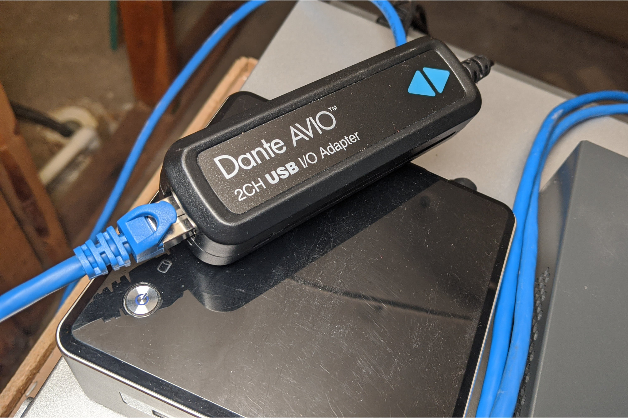
Dante AVIO two channel USB I/O adapter sitting on top of the Intel NUC running Linux and the music servers in the basement.
Now that I have two different music players running on Linux, I need to get the audio out of the Linux box and to the different rooms in my house. I was using Chromecast Audio players but these would randomly appear and disappear from the music apps on my phone. I also had problems with multiroom playback and speaker groups. And they’re IoT junk. Another alternative would be to use a bunch of Sonos Ports but these are expensive at $449 and I would need three to four of them. They’re also IoT junk that rely on a connection to a central server for proper operation.
I vaguely remembered reading a bit about distributing audio over IP networks and decided to research that further. While doing my research, I discovered a company called Audinate that invented a digital audio networking protocol called Dante. I also discovered they made an assortment of adapters for inserting audio into an IP network and pulling audio out of the IP network. These were very affordable compared to the Sonos Port devices at $109 to $144 per adapter.
Each dongle is powered using 802.11af PoE and consumes about 1.5 W. They’re available in a multitude of configurations such as a USB sound card, single and dual channel audio input, single and dual channel audio output, and two channel digital AES input and output adapters. They are configured locally and do not depend on any external 3rd party server for configuration or operation.
I purchased one Dante AVIO 2CH USB I/O adapter and three Dante AVIO 2CH Analog Output adapters for my network. The 2CH USB I/O adapter looks like a USB sound card to the Linux box. Somehow, I was able to configure pulseaudio and alsa to use this adapter as the default sound card for Mopidy and Pianobar.
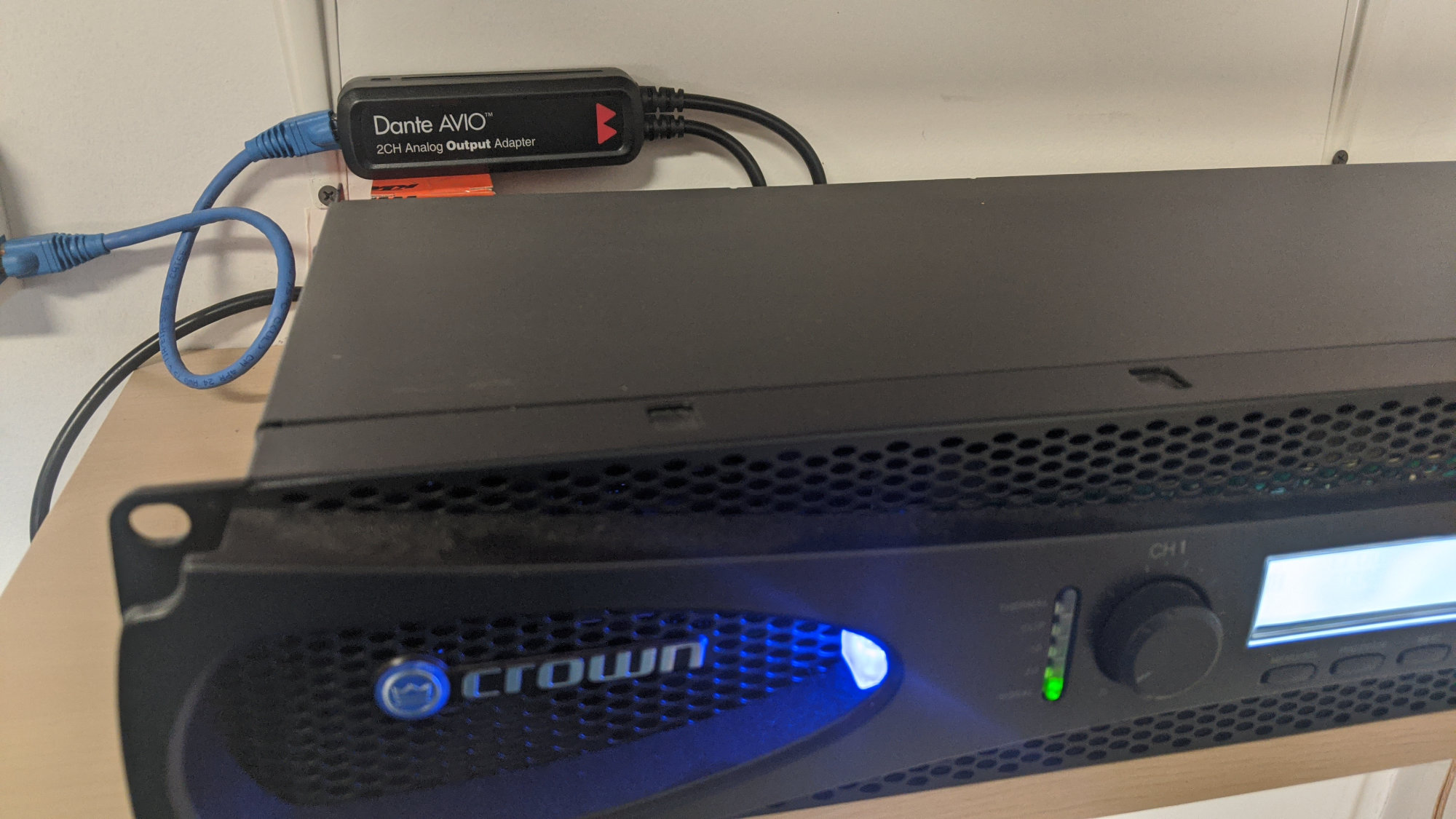
Audinate AVIO Dante two channel output adapter buried behind a Crown XLS amplifier in the garage.
I ran Cat6 Ethernet cables from my Ethernet switch in the basement to each of the locations of the amps and speakers in my house. At each amp, I installed a Dante AVIO 2CH Analog Output adapter. These connect to the amps using XLR connectors. If the amp did not have XLR inputs, I used XLR to 1/8″ mini or RCA cables to connect the adapters to the amps.
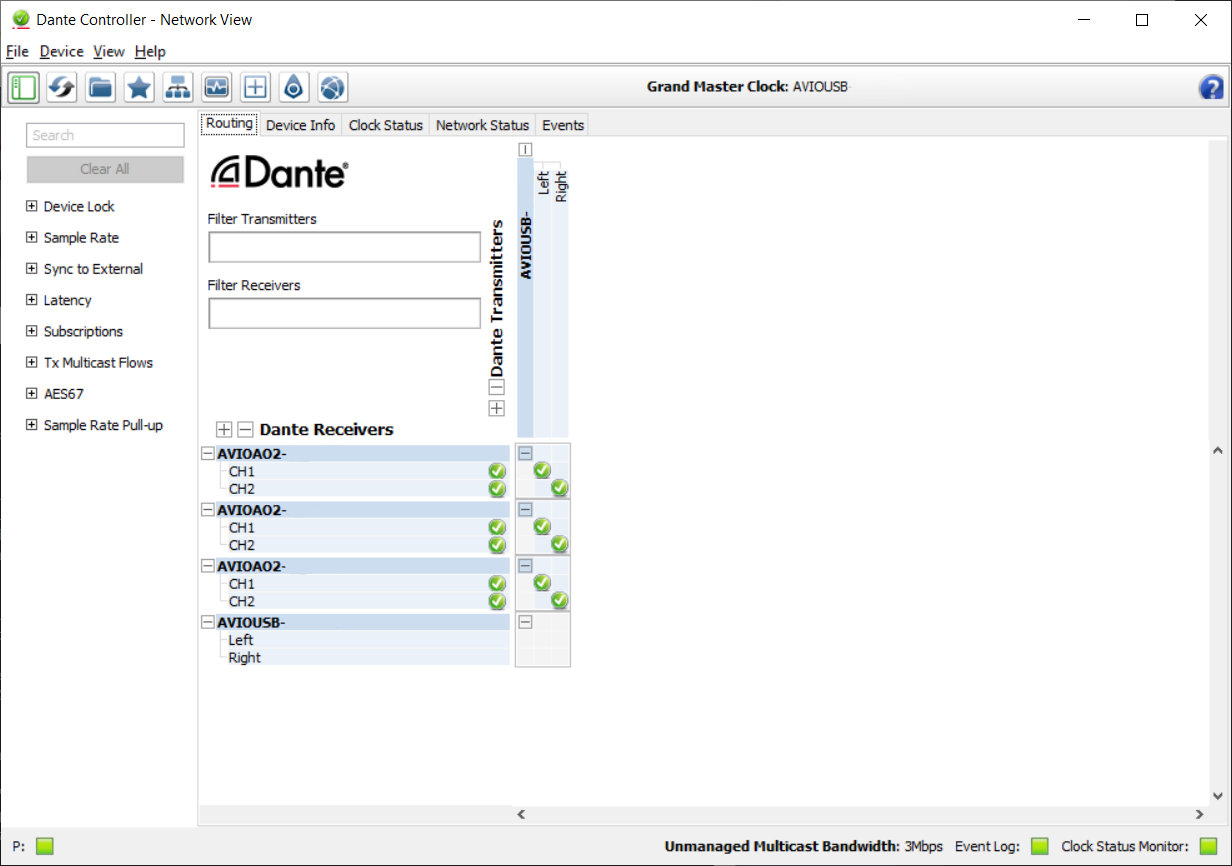
Dante Controller routing interface.
Once the hardware was installed, I used the Dante Controller software running on my Windows PC to route the audio from the 2CH USB adapter to the three 2CH output adapters. Since I have more than two output adapters, this requires creating a multicast flow in the 2CH USB output adapter’s configuration pane then subscribing each of the output adapters to the multicast flow. Once the audio is routed, the Dante Controller software is no longer needed. The adapters remember their configuration across reboots.
To prevent flooding all the ports on your network switch with audio traffic, a managed switch with IGMP snooping is required for the audio network. IGMP snooping detects which ports on a switch are connected to devices that are subscribed to a particular multicast flow and routes packets that are a part of that flow only to those switch ports.
Dante uses IEEE-1588 Precision Time Protocol (PTP) to synchronize the adapters’ clocks and audio playback across the network. To support these functions, the Ethernet switch must also support QoS with DSCP classification and four output queues. Unwanted adapter discovery messages can be isolated from non-audio switch ports using VLANs if desired (1 UDP packet per second per connected adapter).
The best part about Dante digital audio networks is that once the adapters and Ethernet switch are configured properly, everything just works! No fussing with phone apps, desktop PC software, or strange wireless / RF issues.
LED Display Boards
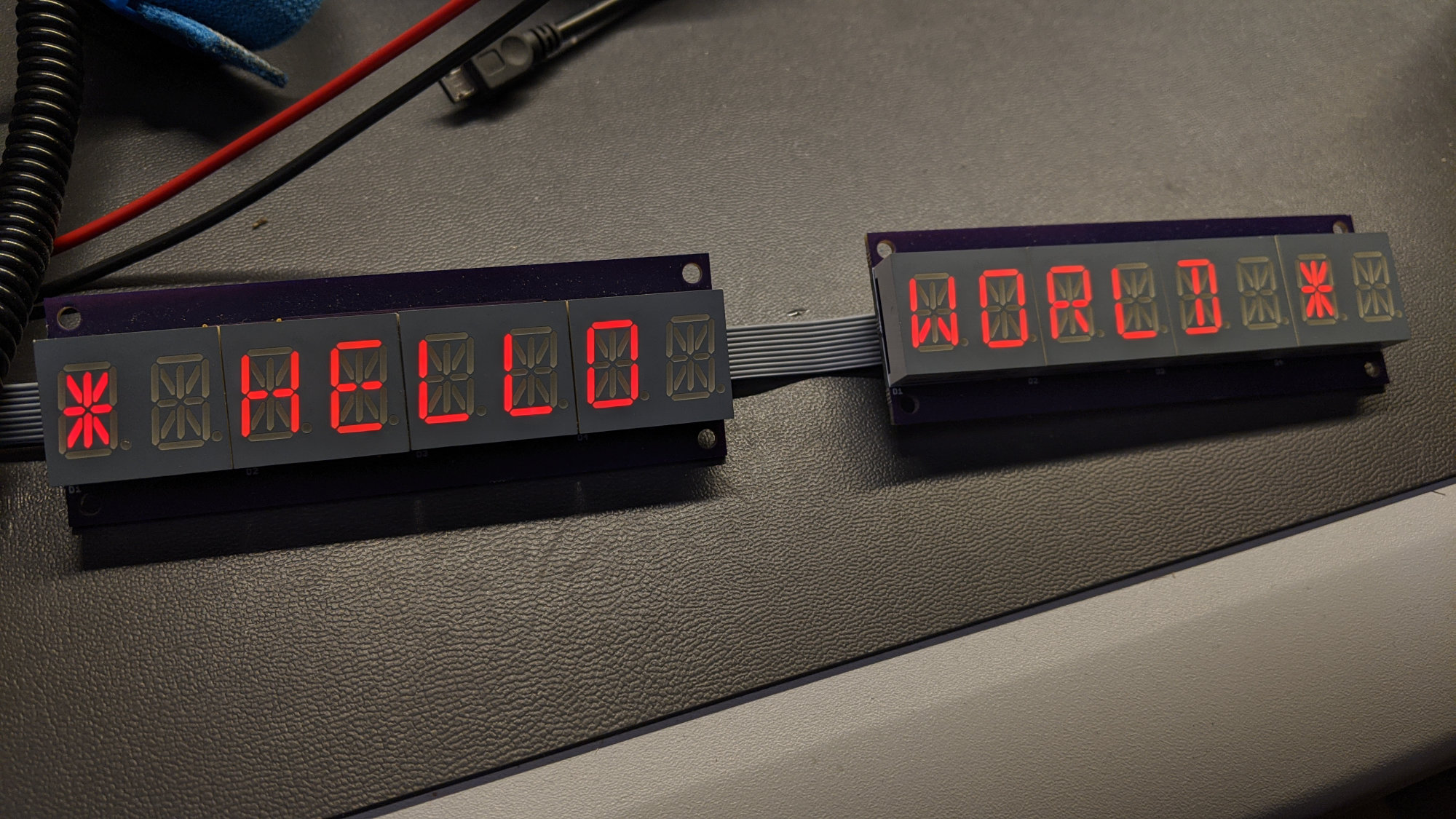
Two daisy chained LED display boards with Kingbright 14-segment red LED displays.
I built these 14-segment LED display boards back in 2016 or 2017. They sat around unused in a box until mid-2020 when I decided to make this project.
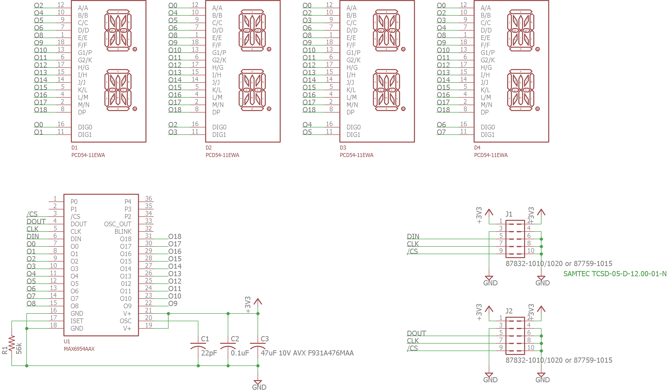
Display board schematic.
Each display board contains four Kingbright dual 14-segment 0.54″ LED displays for a total of eight alphanumeric digits per board. The displays are driven using a Maxim MAX6954 multiplexed LED display driver. The MAX6954 receives commands and ASCII display data over a SPI interface. The ASCII characters are decoded and displayed on the displays. Resistor R1 sets the display current and the combination of resistor R1 and capacitor C1 sets the display refresh rate.
Each display board has two 10-position, 2mm pitch, dual-row headers, J1 and J2. J1 is the power and data input connector. J2 is a power and data output connector. Boards may be chained together by connecting J2 on the previous board to J1 on the next board. The first board’s J1 is connected to a +3.3 V power supply for power and a microcontroller with 3.3 V I/O for configuration and display data.

Display board layout.
The completed board layout is shown in the image above. Displays D1 to D4 are on the front of the board and all other components are on the rear of the board. Holes in each corner of the board allow mounting the board to the front or rear panel of an enclosure.
Wireless Controller and Power Supply Board
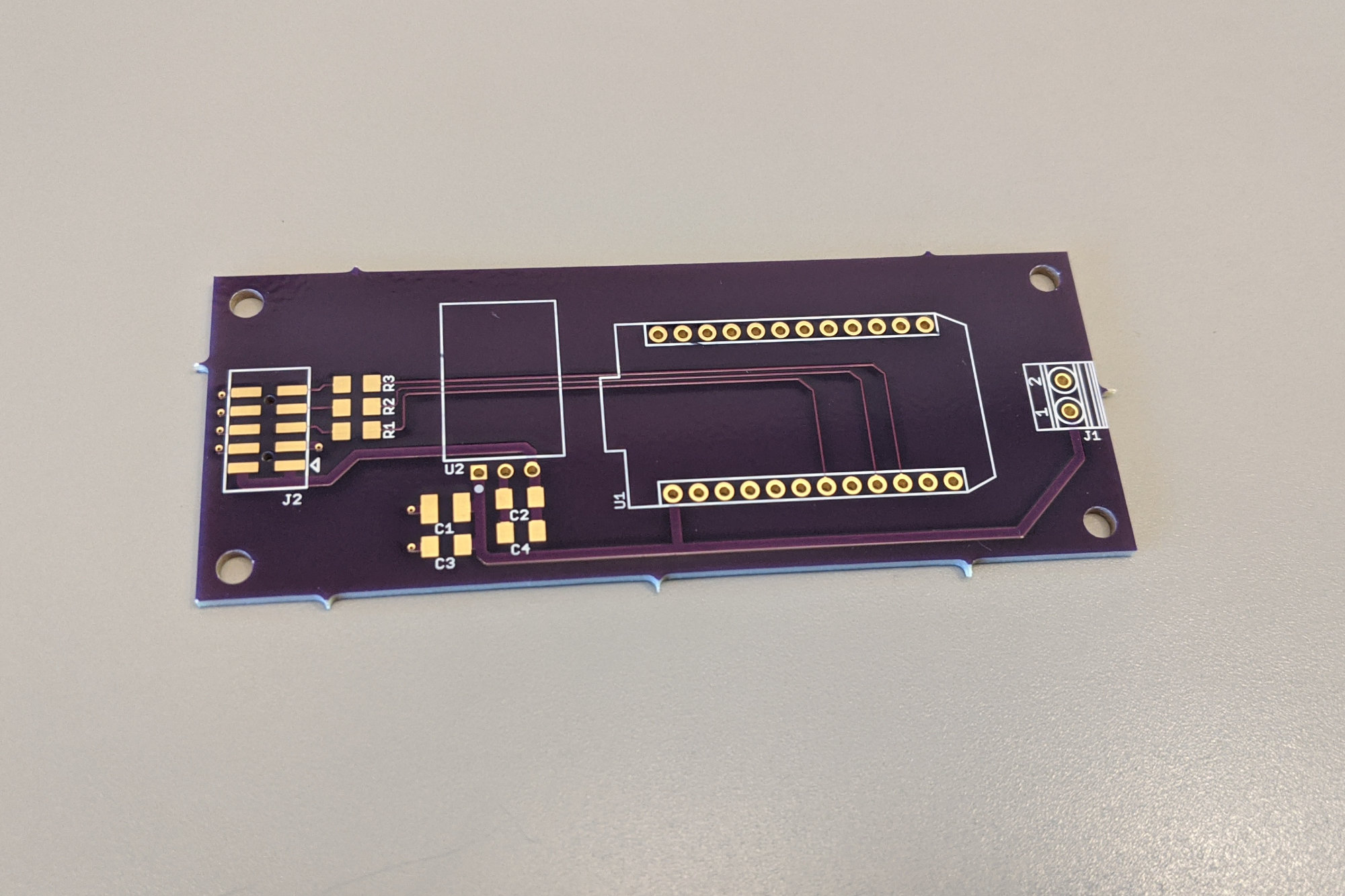
Display controller board housing the 3.3 V power supply and Particle Photon.
The control and power supply board is designed to mount to the rear of the enclosure in between the standoffs that hold the LED display boards. Unfortunately, I didn’t round the corners on the first revision of the board and I failed to account for the width of spacers holding the LED boards when designing this board and the enclosure. It’s a tight fit but it does fit and it does work. I rounded the corners on the version of the board in the Github repository. I would also suggest trimming 25 mil from each end of the board when making your own version of this board.
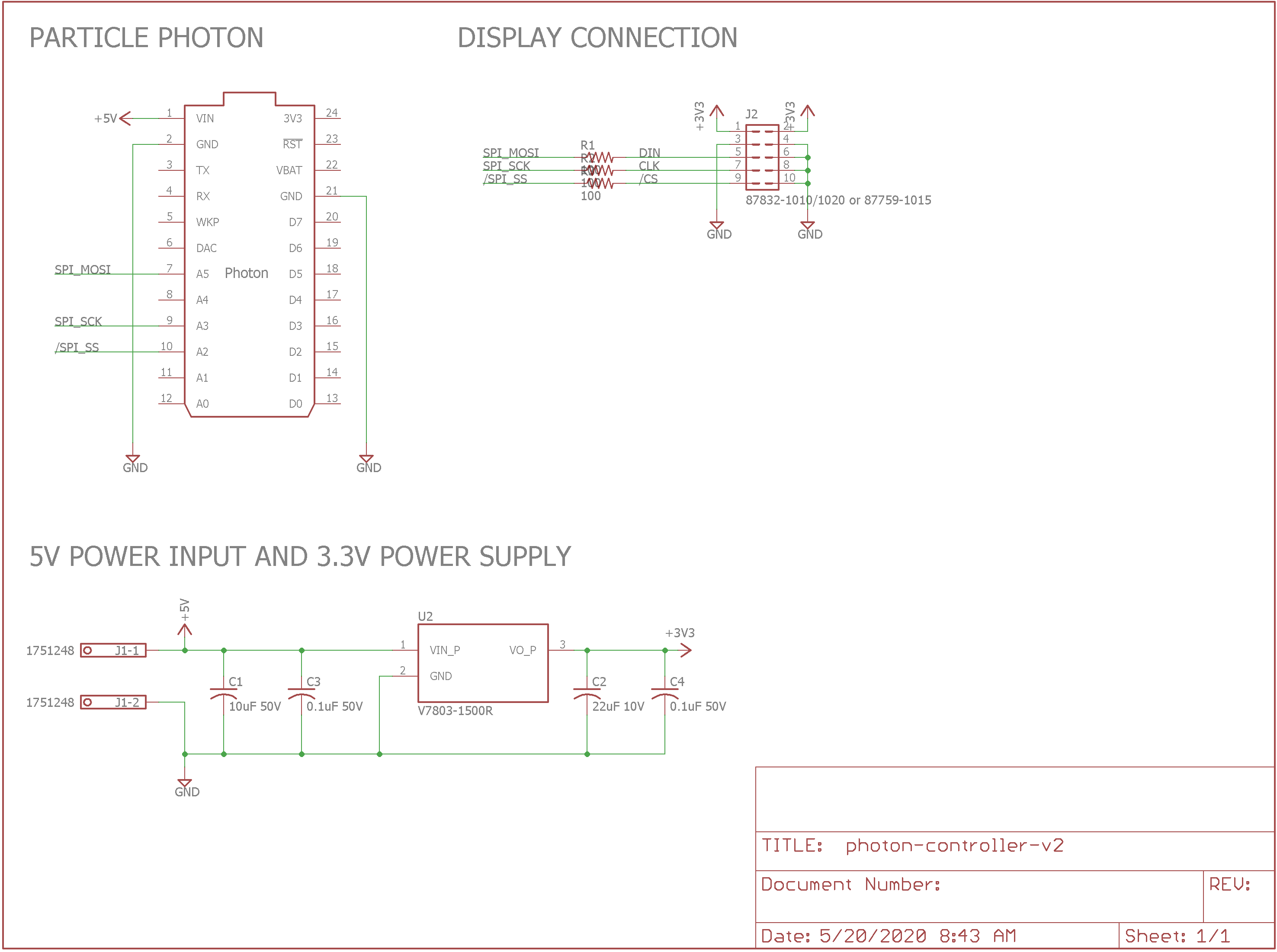
Control board schematic.
J1 is a 3.5mm pitch screw terminal block for inputting +5 V to the control and power supply board. A 3.3 V, 1500 mA linear regulatory replacement DC/DC converter supplies +3.3 V power for the LED displays on J2. A Particle Photon is the brains of the project. It’s powered directly from the +5V power input. The SPI interface on the Particle Photon connects through R1, R2, and R3 to J2. J2 connects to the first LED display board in the chain of display boards.
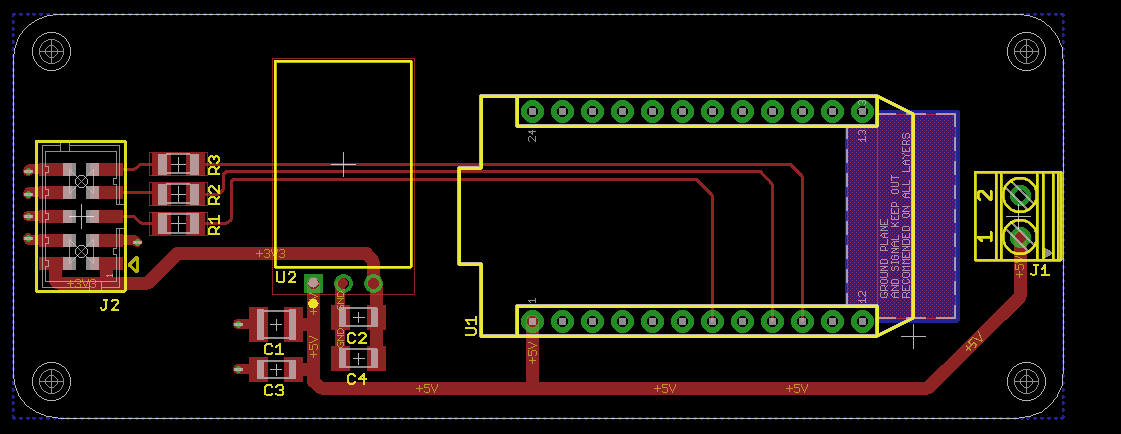
Control board layout.
Above is the completed board layout with rounded corners. If you do decide to trim 25 mil off each end of the board, be sure to leave the screw holes exactly where they are.
Software
The software runs on a Particle Photon and is built using their online build environment at build.particle.io. The software uses a random websockets client library I found on the Internet and the ArduinoJson library. The version of the websockets client that I initially used did not handle large packets correctly. I rewrote the TCP stream parser in the library to support large packets properly. It’s not perfect but it is better.
The websockets client library is instantiated twice in the design. The first client connects to the Mopidy websocket server to receive the playback state, track information, and volume from the Mopidy server. The second client connects to my node.js websocket server to receive information from Pianobar about the currently playing track. The ArduinoJson library is used to parse the JSON formatted responses from the two websocket clients.
When the software first connects to the Mopidy server, it sends JSON formatted commands to the server to retrieve the current playback and volume states. This information is displayed immediately on the display if it’s available. Pianobar does not support querying for the current state so if you’re using Pianobar, you have to wait until the next track for the display to update after power up.
The onMessage function parses the JSON messages from the Mopidy websockets server. The onMessage2 function parses the JSON messages from the node.js Pianobar websockets server. The Mopidy onMessage function is quite a bit more complicated than the Pianobar onMessage2 function because it supports displaying the pause and volume states of the server.
Each function sets or clears the pianoBarMode boolean to indicate if the last received message was from Mopidy or Pianobar. This flag is used by the scrolling message display function to handle display time outs and what information can be displayed on the display.
The tick_50Hz function is called using a timer every 20 ms. This timer handler function in turn calls the scroll_Tick function. The scroll_Tick function implements display time outs and the scrolling display. One such time out is used when the Mopidy volume changes. The new volume level is displayed immediately then after a delay of one second, the display reverts to its previous state. Another time out is used to clear the display when the track / artist / album information from Pianobar hasn’t been updated in ten minutes.
The ArduinoJson library built into the Particle build environment does not support some unicode characters. There’s an odd unicode way that Spotify specifies an apostrophe in some, but not all, song titles. When this occurs, the ArduinoJson parser fails and the display blanks until the next song. An easy fix would be to search the message string in onMessage for the offending unicode string and replace it with a simple ASCII apostrophe.
Enclosure Design
Enclosure render in Autodesk Fusion 360.
I designed the enclosure in Autodesk Fusion 360 and Front Panel Express in a half hour over lunch at work. This is one reason I missed the getting the width of the control board correct.
The enclosure consists of a red acrylic front panel, black anodized aluminum rear, top, bottom panels, and black anodized extruded profiles for the left and right side. The top and bottom panels and the left and right side profiles are identical.
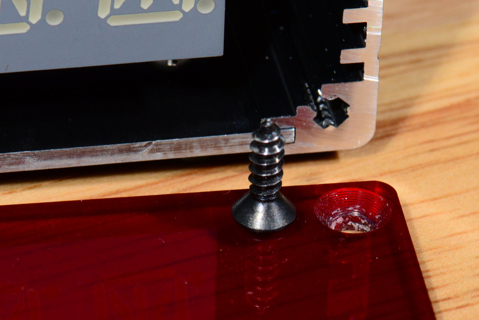
The front panel contains four screw holes with countersinks to hold the panel to the aluminum side extrusions. The rear panel contains the same screw holes plus cutouts for the Wi-Fi antenna, the DC power jack, and the screw for the standoffs that hold the boards.
Assembly
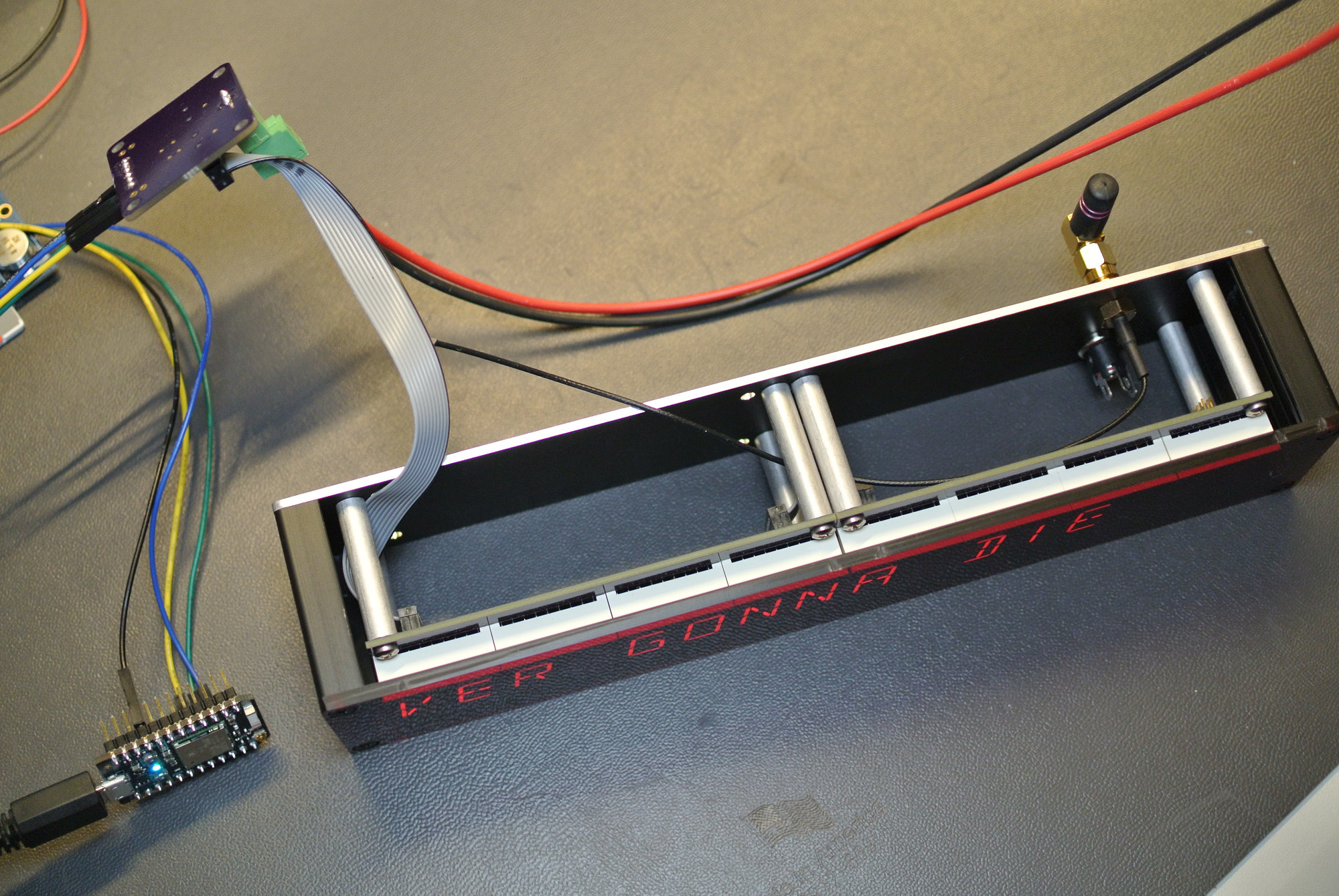
Initial assembly before the controller board and top and bottom panels arrived.
I assembled the project in pieces as the parts arrived. In the photo above, you can see the partially assembled project before the top and bottom panels and control / power board arrived. Eight 4-40 threaded 1.25″ long x 0.25″ diameter standoffs hold the LED display boards to the rear panel. The rear panel also has the DC power jack, RP-SMA to U.FL cable, and Wi-Fi antenna mounted to it.
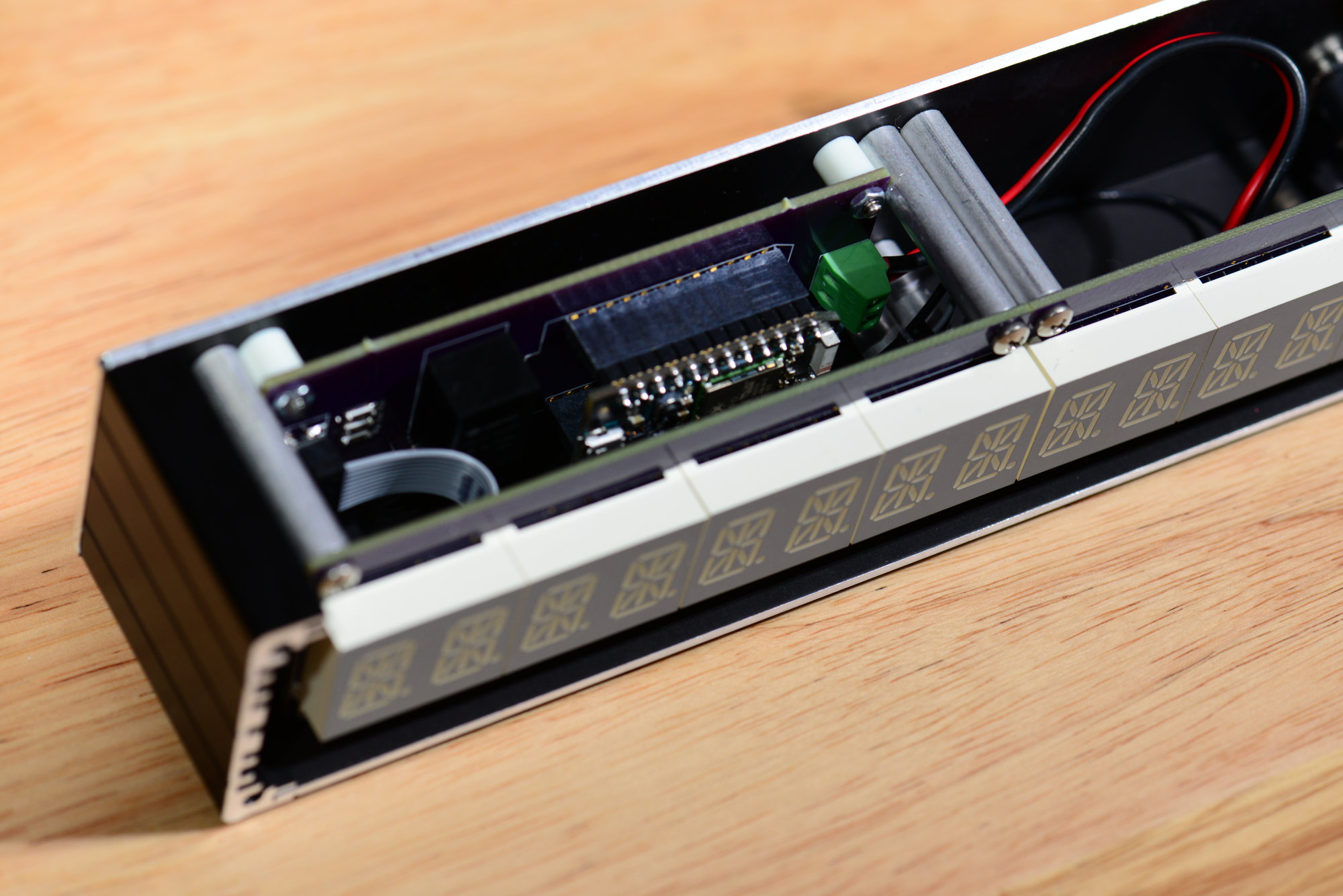
Location and mounting of the control board in the enclosure.
Once the control board arrived, I placed it behind the left most display board and fixed it in place using four 1/4″ long x 1/4″ diameter unthreaded spacers, four 4-40 x 1/2″ screws, and four 4-40 hex washers. It’s connected to the first display board using a two-inch, 2mm pitch cable. The U.FL cable is connected the Particle Photon’s external antenna connector and the DC power jack is wired to the green screw terminal block on the control board.

Close up of the rear of the 2nd LED display board.
The second LED display board connects to the first LED display board using a two-inch, 2mm pitch cable.
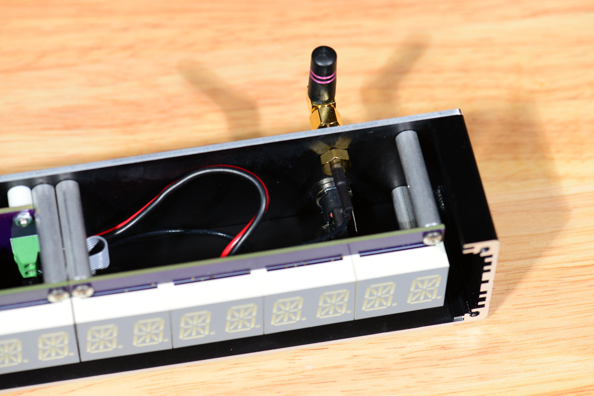
Close up of the DC jack and Wi-Fi antenna.
The photo above is a close up of the DC jack, RP-SMA jack to U.FL cable, and Wi-Fi antenna.
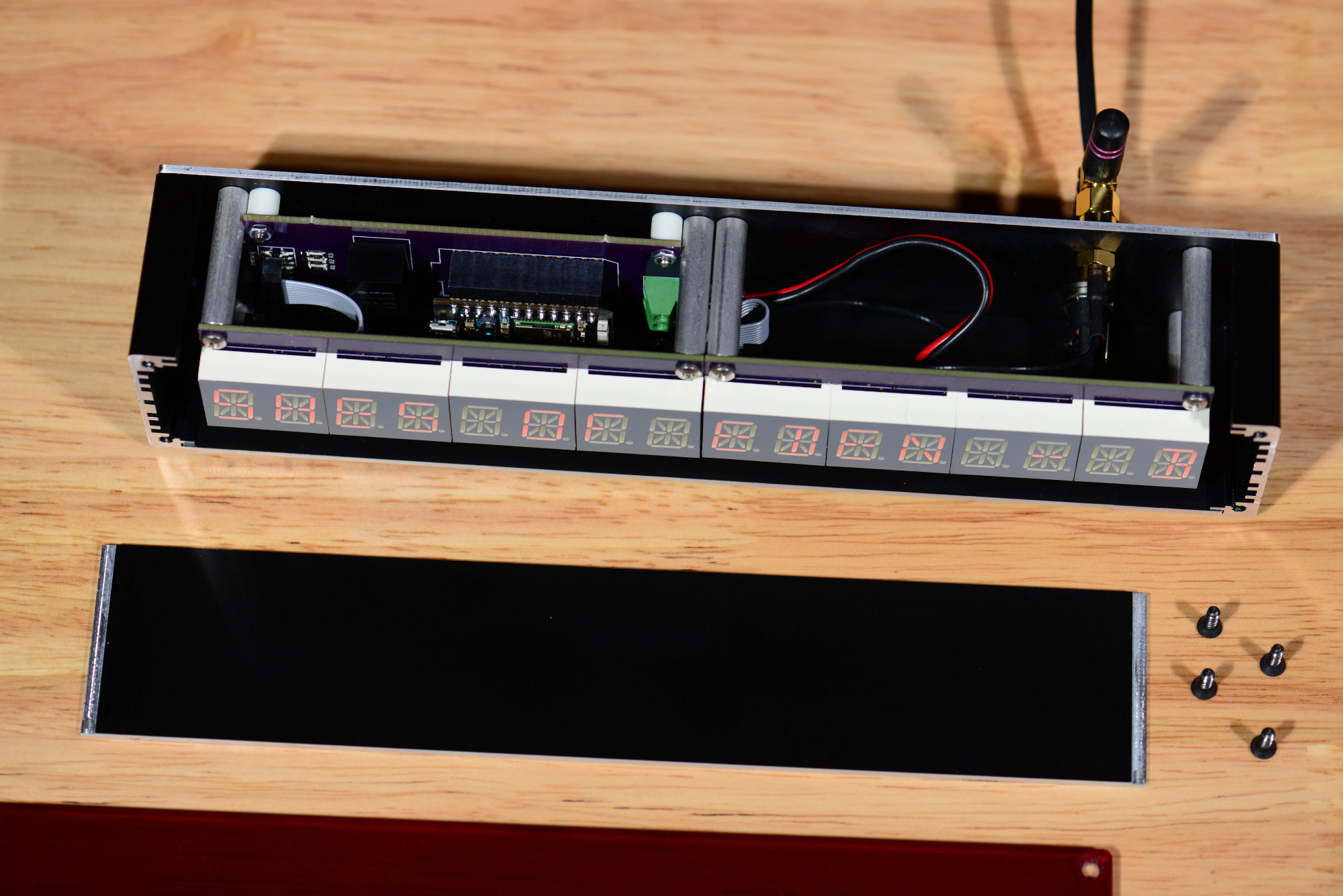
The enclosure and electronics are almost completely assembled.
The photo above shows the almost completely assembled project. You can see the placement and routing of all the cables inside the enclosure.
Tool paths.
If you look closely, you can see the CNC tool paths in the countersink for the screw in the enclosure’s acrylic front panel.
The completed music server remote track/artist/album display.
The front view of the completed music server remote track/artist/album display.
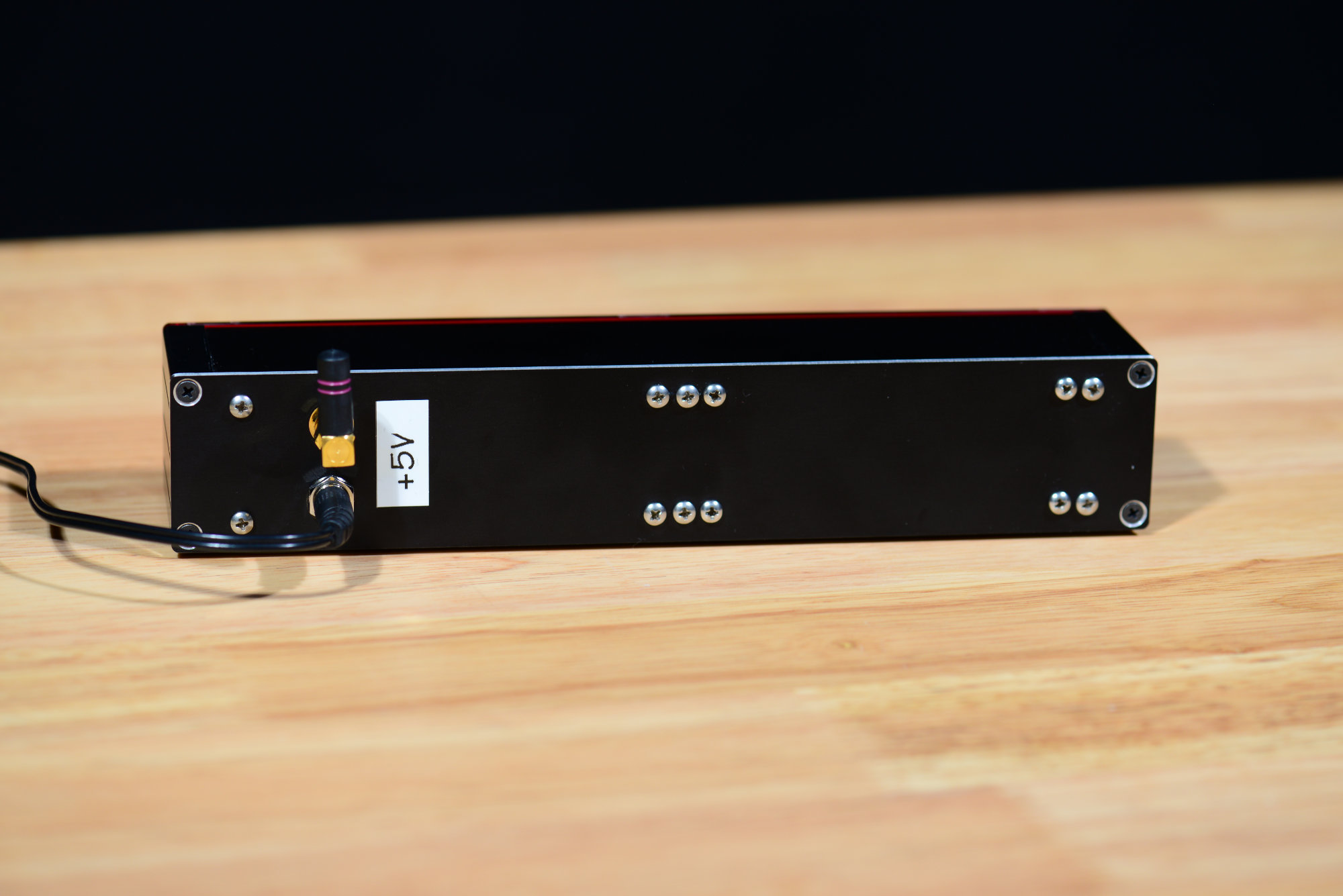
Rear view of the completed music server remote track/artist/album display.
The rear view of the completed music server remote track/artist/album display. I stuck a label near the DC power jack to remind me which DC power supply to use with the display.
Bill of Materials
The bills of materials for the LED board, control board, and off-board parts of the project are listed in the sections below.
LED Board
These are the parts required for one board. You will need to double the quantities for two boards.
| Qty | Parts | Description | Mfr | Mfr Part # |
| 1 | C1 | 22pF, 10V, 1206 | — | — |
| 1 | C2 | 0.1uF, 10V, 1206 | — | — |
| 1 | C3 | 47uF, 10V, 1206 | AVX | F931A476MAA |
| 4 | D1, D2, D3, D4 | Dual 14-segment LED display | Kingbright | PCD54-11EWA |
| 2 | J1, J2 | SMD 10 position 2.00 mm header | Molex | 87759-1015 |
| 1 | U1 | LED Display Driver | Maxim | MAX6954AAX+ |
| 1 | R1 | 56k, 5%, 1/4W, 1206 | — | — |
Controller Board
These are the parts required for the control board.
| Qty | Parts | Description | Mfr | Mfr Part # |
| 1 | C1 | 10uF, 16V, 1210 | — | — |
| 1 | C2 | 22uF, 10V, 1206 | — | — |
| 2 | C3, C4 | 0.1uF, 16V, 1206 | — | — |
| 1 | J1 | 2 position, 3.5mm PCB screw terminal block | Phoenix Contact | 1751248 |
| 1 | J2 | SMD 10 position 2.00 mm header | Molex | 87759-1015 |
| 3 | R1, R2, R3 | 100, 5%, 1/4W, 1206 | — | — |
| 1 | U1 | Particle Photon w/ Headers | Particle | PHOTONH |
| 1 | U2 | 3.3V DC/DC converter | CUI Devices | V7803-1500R |
| 2 | — | Single-row, 0.1″, 12 position header socket | Samtec | SSW-112-01-G-S |
Off-Board Parts
These are the parts that are mounted on the enclosure.
| Qty | Parts | Description | Mfr | Mfr Part # |
| 1 | — | RF ANT 2.4GHZ WHIP RA RP-SMA MAL |
Linx Technologies Inc. |
ANT-2.4-CW-RAH-RPS |
| 1 | — | CONN PWR JACK 2.1X5.5MM SOLDER | CUI Devices | PJ-005A |
| 1 | — | CBL ASSY RP-SMA-UMC 7.874″ | Amphenol RF | 336314-13-0200 |
| 8 | — | 1/4 RD X 1-1/4 LENGTH | RAF Electronic Hardware | 1696-440-AL |
| 4 | — | ROUND SPACER NYLON 1/4″ | Essentra Components | R911-4 |
| 16 | — | MACHINE SCREW PAN PHILLIPS 4-40 1/4″ | Keystone Electronics | 9900 |
| 4 | — | MACHINE SCREW PAN PHILLIPS 4-40 1/2″ | Keystone Electronics | 9902 |
| 4 | — | HEX NUT 3/16″ STEEL 4-40 | Keystone Electronics | 4694 |
| 2 | — | 2″, 2.00mm pitch, 10-position cable assembly | Samtec | TCSD-05-D-2.00-01-N |
| 1 | — | Front panel. | Front Panel Express | — |
| 1 | — | Rear panel. | Front Panel Express | — |
| 2 | — | Top / bottom panel | Front Panel Express | — |
| 2 | — |
Side Profile 1, black anodized, Length: 42.1mm
|
Front Panel Express | GLGP1013 |
| 1 | — | Enclosure assembly kit | Front Panel Express | GGMS1122 |
| Heat shrink tubing | ||||
| Red and black hookup wire |
Design Files
The design files for this project are in remote-display directory inside the music-server-remotes repository in my Github account.