
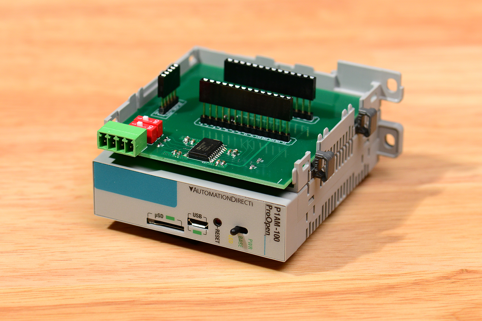
The completed RS-422 / RS-485 shield for the Automation Direct P1AM-100 open source PLC.
The RS-422 / RS-485 shield is an open source shield designed to add RS-422 and RS-485 communication capabilities to the ProductivityOpen family of open-source programmable logic controllers (PLC’s) from Automation Direct. It’s loosely based on the Arduino MKR RS-485 shield but updated to use an ADM2582E 3.3 V isolated RS-485 transceiver from Analog Devices. The completed shield fits inside the P1AM-PROTO prototyping enclosure.
If you’re not familiar with the expansion capabilities of the Automation Direct P1AM-100 Open-Source PLC, now would be a good time to read my previous blog post on the subject. For this project, I’m going to create a new design using the Eagle PCB library symbol created in that post then add an isolated RS-422 / RS-485 transceiver and its support circuitry.
Selecting an RS-422 / RS-485 Transceiver
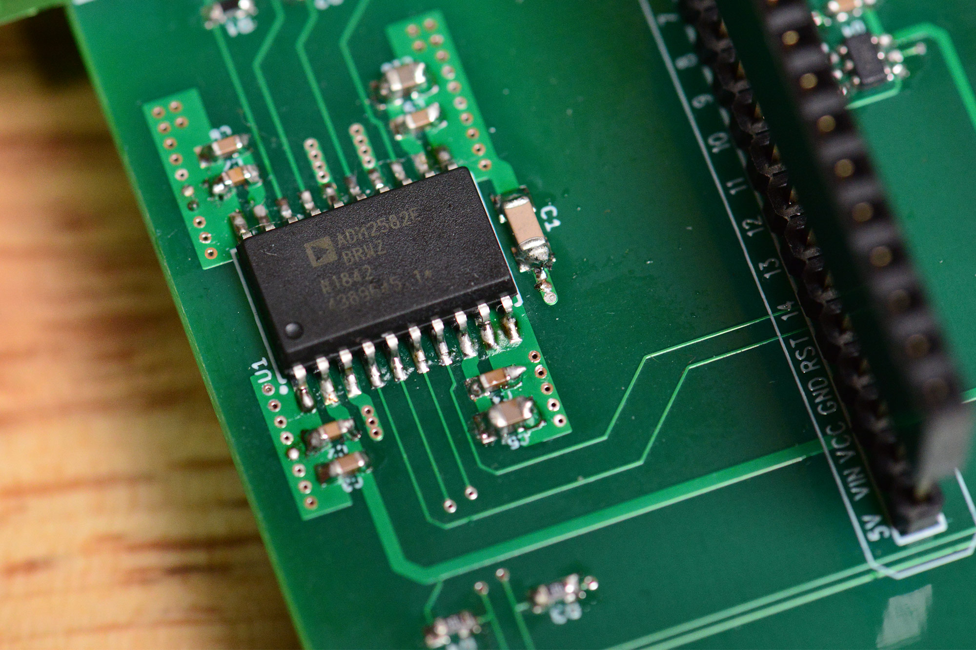
The ADM2582E in an SOIC-20 package.
My go to RS-485 transceiver is the Texas Instruments SN65HVD11. It’s a half-duplex transceiver that runs from 3.3 V and has a maximum date rate of 10 Mbps. It’s not isolated but does have reasonable built-in ESD protection. It’s been superseded by devices like the THVD2450 which are pin-for-pin compatible while offering a wider supply voltage range, faster data rates, and better ESD protection.
While browsing the Automation Direct forums, I learned of the Arduino MKR RS-485 shield. Many of the people there liked this shield but did not like the idea of an exposed shield hanging off the side of their PLCs—especially in an industrial environment. This board has screw terminals for I/O and uses the Maxim MAX3157 full-duplex, isolated RS-422 / RS-485 transceiver. Unfortunately, the Maxim transceiver is a 5 V-only part and the data sheet does not mention any ESD protection.
While doing more research for this project, I remembered I have a bunch of Digilent RS-485 PMOD modules from building the Zombie Containment Unit a few years ago. The Digilent PMOD uses an Analog Devices ADM2582E transceiver. The ADM2582E is isolated, runs from a single 3.3 V supply, is capable of full or half-duplex operation, has a maximum data rate of 16 Mbps, and has solid, built-in ESD protection. It’s the perfect part for this project.
Design Requirements
The list below summarizes the requirements for the design:
- Be compatible with the P1AM-100 PLC controller.
- Fit in the P1AM-PROTO prototyping enclosure.
- Does not interfere with the operation of P1000 bus modules. This precludes the use of the A3 and A4 pins for I/O on this shield.
- Does not interfere with the operation of the P1AM-ETH Ethernet shield. This requires the SPI bus to be shared by this shield and the Ethernet shield. It also precludes the use of digital I/O pin 5 on this shield.
- Uses the Analog Devices ADM2582E transceiver.
- Has a plugable screw-terminal block for I/O.
- Has switchable 120 Ω termination for both the receive and transmit data lines.
- Includes a Microchip 25AA02E48T-I/OT serial EEPROM with pre-programmed Ethernet MAC address for serial number or Ethernet applications.
Schematic
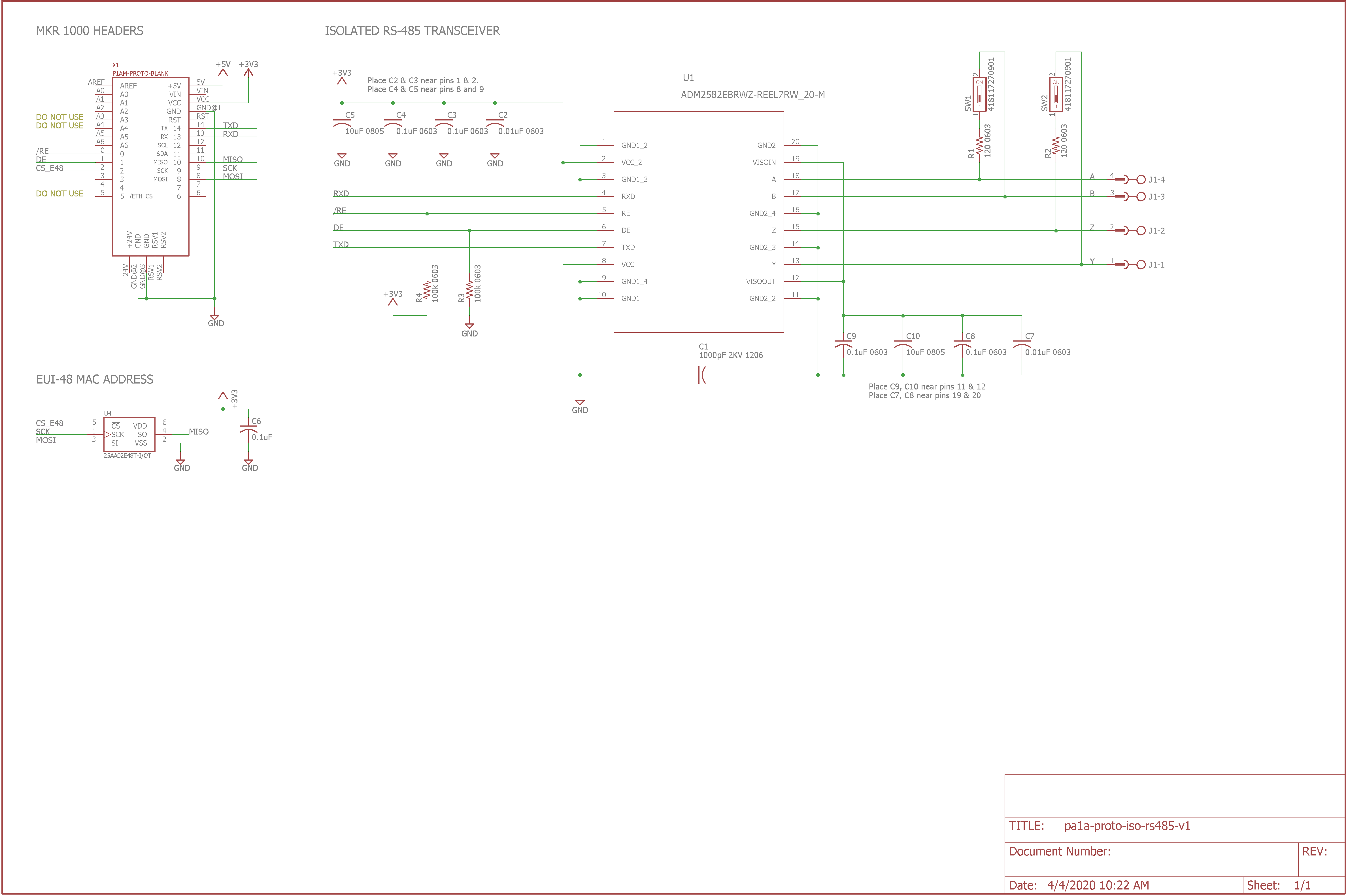
Schematic for the isolated RS-422 / RS-485 shield.
The schematic is divided into three main sections. In the upper left is the Arduino MKR symbol from my P1AM-PROTO-BLANK Eagle PCB library. This library component includes the symbol, the pads for the headers, and the board outline required by the P1AM-PROTO enclosure and P1AM-100 controller.
Below that is a Microchip serial EEPROM with a pre-programmed EUI-48 identifier. The EUI-48 identifier can be used as a globally-unique Ethernet MAC address or as a serial number for this board.
To the right of the MKR connector is the ADM2582E RS-485 transceiver. This is basically the circuit from the data sheet with two ferrite beads removed, switchable termination added, and weak pull-ups and pull-downs on the receiver disable and transmitter enable lines respectively. The weak pull-ups and pull-downs disable the receiver and transmitter until the software running on the P1AM-100 controller has a chance to initialize the transceiver.
Per the guidance in the data sheet, a 1000 pF, 2 kV capacitor is connected between pins 10 and 11 to “providesa return path for high frequency common-mode noise currents across the isolation gap.”
Board Design
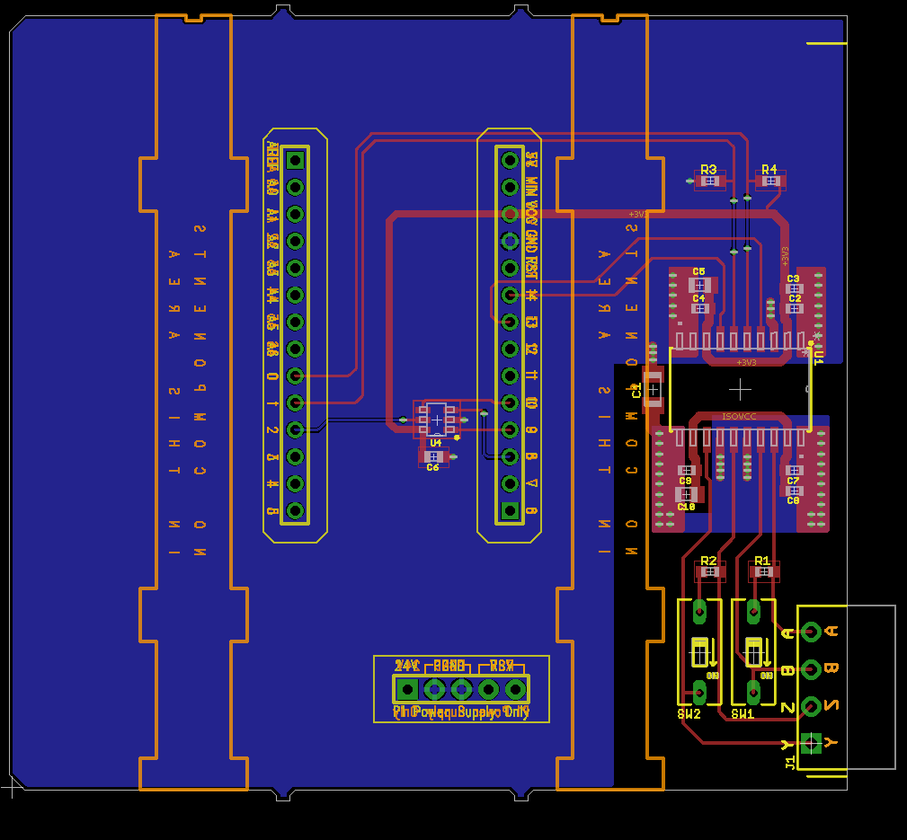
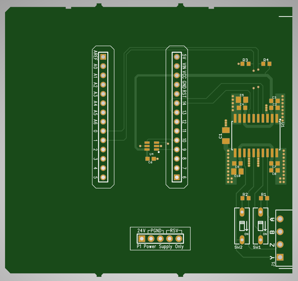
Board design for the isolated RS-422 / RS-485 shield.
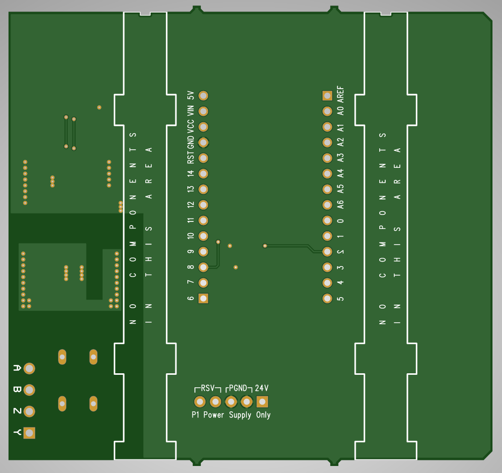
The completed board design is shown in the image above. No components can go inside the yellow regions around the headers to prevent interference with the plastic enclosure. In addition, no SMD components can go on the bottom of the board in the orange regions to prevent interferance with the sliding latches that lock the enclosure to the P1AM-100 CPU or other shield. The leads of through-hole components must avoid these areas too.
I tried to follow the recommended layout guidelines for the transceiver as best I could given the constraints of a two-layer board. The ground pins in the corners are the primary heat dissipation points for the chip so the pads are little larger, the traces are routed using pours, and the pours are tied into the non-isolated and isolated ground planes using many vias.
A large isolation barrier needs to be maintained between non-isolated and isolated parts of the design. This is clearly visible in the board design above. Only two components cross the isolation barrier—the high-voltage capacitor and the transceiver itself.
Board Manufacturing
After creating my Gerbers, I previewed them using a free online Gerber viewer.
Top View
Top view of the completed board.
Bottom View
Bottom view of the completed board.
X-ray View
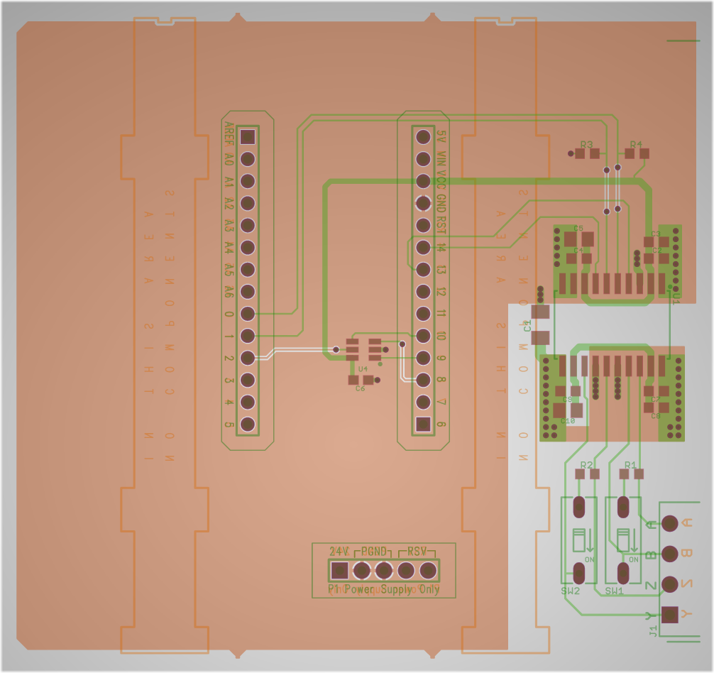
X-ray view of the completed board.
I was happy with the previews so I ordered the boards.
Finished Boards
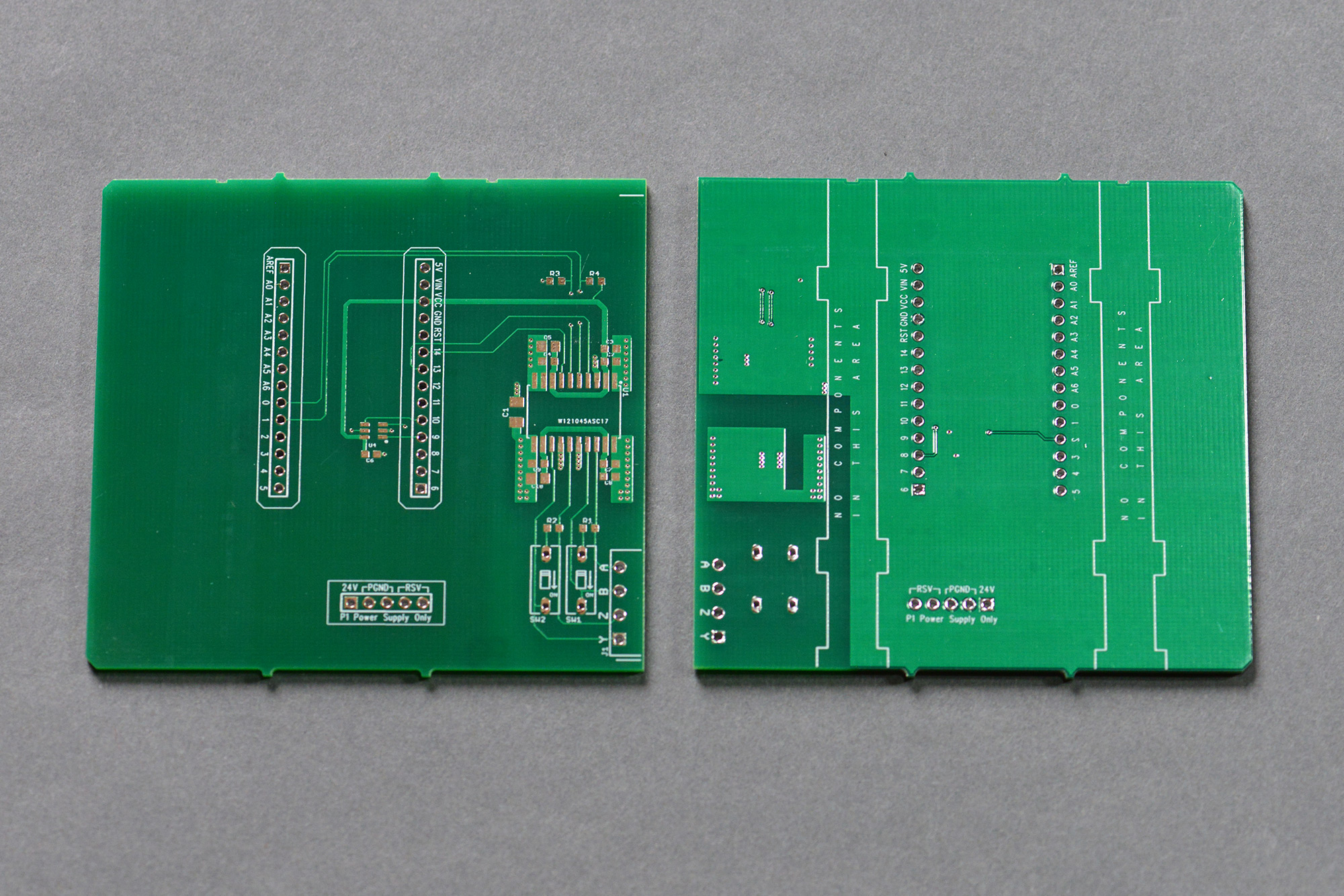
Unpopulated boards back from the board house.
Above is a photo of the finished boards. This is a lead-free HASL finish.
Populating the Board
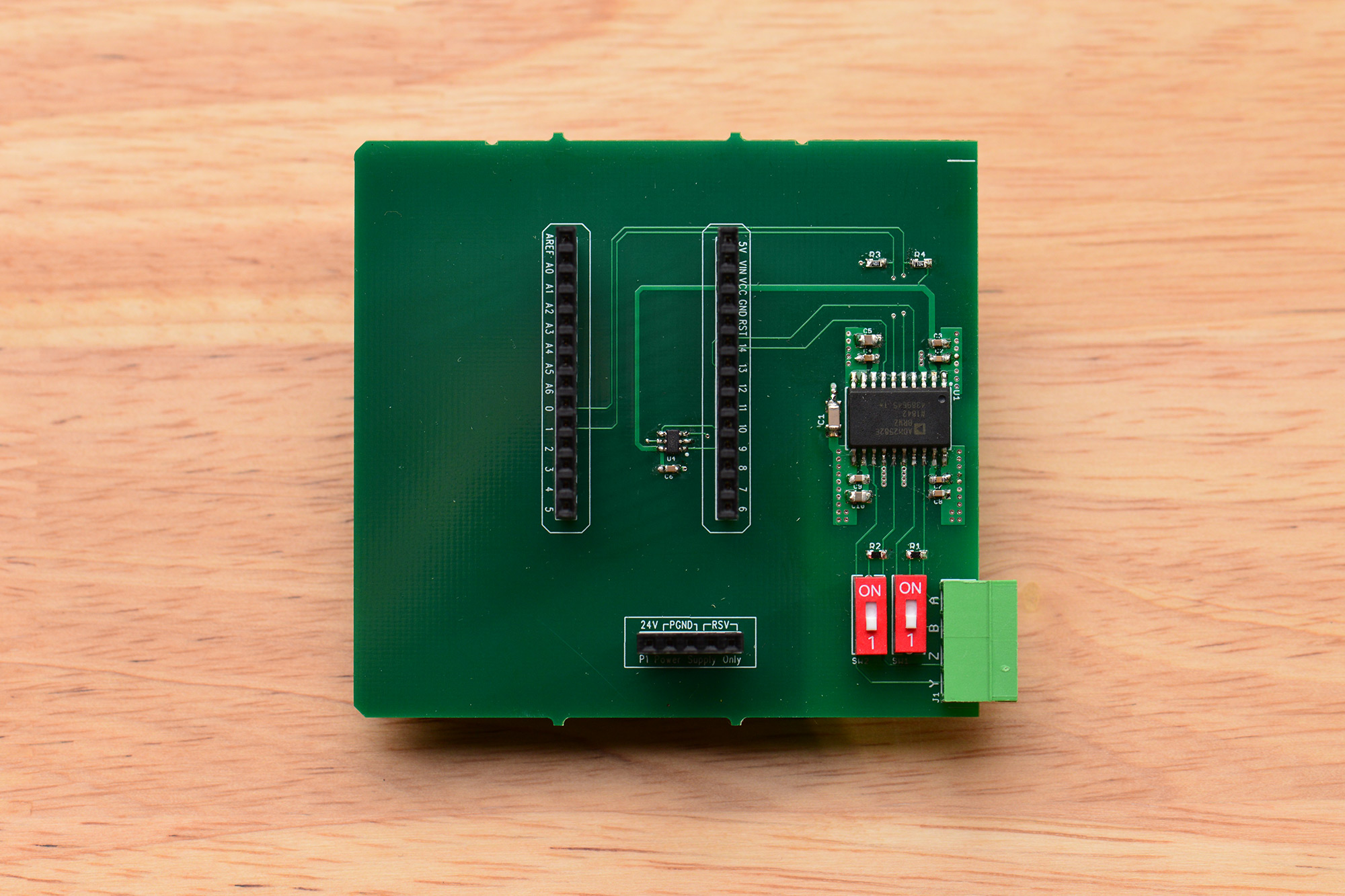
The completed and fully-populated RS-422 / RS-485 shield.
The next step was to populate the board. I populated the board by hand using a pretty big chisel soldering iron, quality lead-free tin/silver/copper solder, and lots of paste flux. This board was the third P1AM-PROTO form factor board I stuffed and, as a result of much practice, was also the easiest of the three.
Testing the Board
To test the board hardware, I used two tests. The first test was a loopback test to verify the basic functionality of the board. The second test was a test of board-to-board communications using a 2nd P1AM-100 and a 2nd RS-422 / RS-485 transceiver.
Loop Back Test
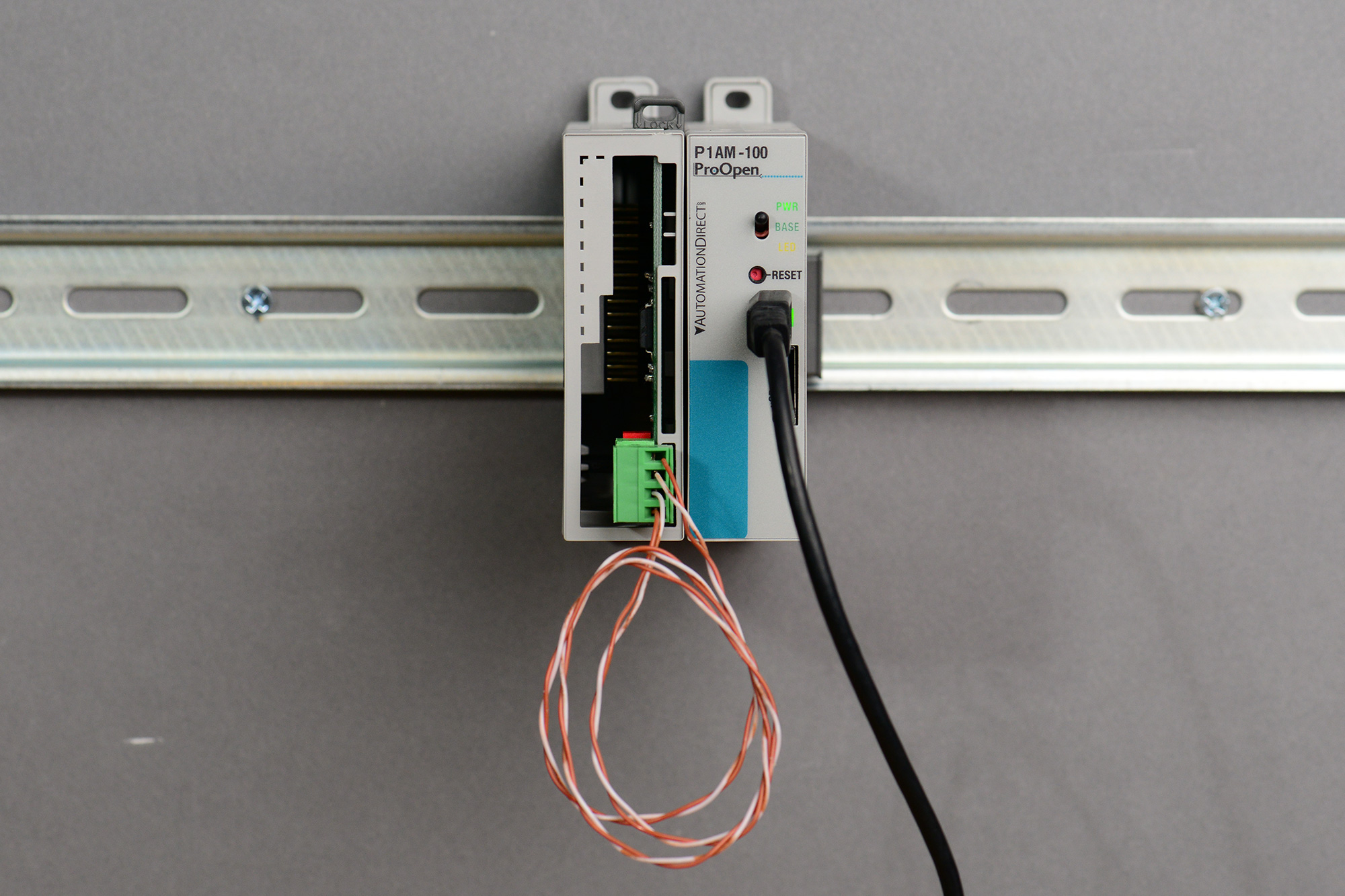
Hardware setup for the loopback test.
For the loopback test hardware, I connected the A and Y terminals together and the B and Z terminals together using two short loops of wire and the four-position screw terminal block. For the loopback test software, I wrote code to initialize the hardware then echo characters from the Serial console port to the secondary TX/RX pins Serial1 port and vice versa. I also added a feature to the software to enable or disable the ADM2582E’s transmitter and receiver based on the state of the built-in toggle switch on the P1AM-100.
To use the software, compile and download the p1am-100-iso-rs485.ino sketch. Open the serial monitor window. The software will display Hello, world! and the MAC address read from the serial EEPROM on the serial monitor.
Now type some characters into the serial monitor. With the built-in toggle switch down or the screw terminal block unplugged, characters typed on the serial monitor should not appear in the serial monitor window. With both the built-in toggle switch up and the screw terminal block connected, characters typed on the serial monitor should appear in the serial monitor window.
Board-to-Board Communication Test

Improvised board-to-board communication test.
The second test is a board-to-board communications test. This test uses two P1AM-100’s and two sets of RS-485 hardware. One pair of a Cat5E Ethernet cable is used to connect the A and B terminals on unit #1 to the Y and Z terminals on unit #2. A second pair of the same Cat5E Ethernet cable is used to connect the A and B terminals on unit #2 to the Y and Z terminals on unit #1. This forms a full-duplex communications link between both units. I only have one of my RS-422 / RS-485 shields so I had to improvise and use a Digilent RS-485 PMOD on the second unit.
The software from the loopback test is now loaded onto both units. I quit the Arduino IDE and used two TeraTerm windows to open a serial connection to each unit. When the built-in toggle switch is up on both units, characters typed into one TeraTerm window should appear in the opposite unit’s TeraTerm window and vice versa. With either toggle switch down, characters that are typed should not be echoed.
Example Application: Reproduce Switch Closures at a Distance

Hardware used to develop the example application.
In my example application, the state of the eight inputs on a P1-08ND3 input module connected to a first P1AM-100 PLC are relayed over RS-422 / RS-485 to the eight outputs on a P1-08TRS output module connected to a second P1AM-100 PLC. Every 20 ms, the inputs are sampled and sent as a single byte over the serial communications link to the remote P1AM-100. The remote P1AM-100 receives the byte and updates its relay outputs.
The example application sketch may be downloaded here. The sender sketch runs on the P1AM-100 with the input module attached. The receiver sketch runs on the P1AM-100 with the output module attached. This example application is not very robust. In a real world application, link faults and data errors need to be detected to ensure the integrity of the system.
Hardware and Software Design Files
Hardware and software design files for this project may be download from the project’s repository on Github.