
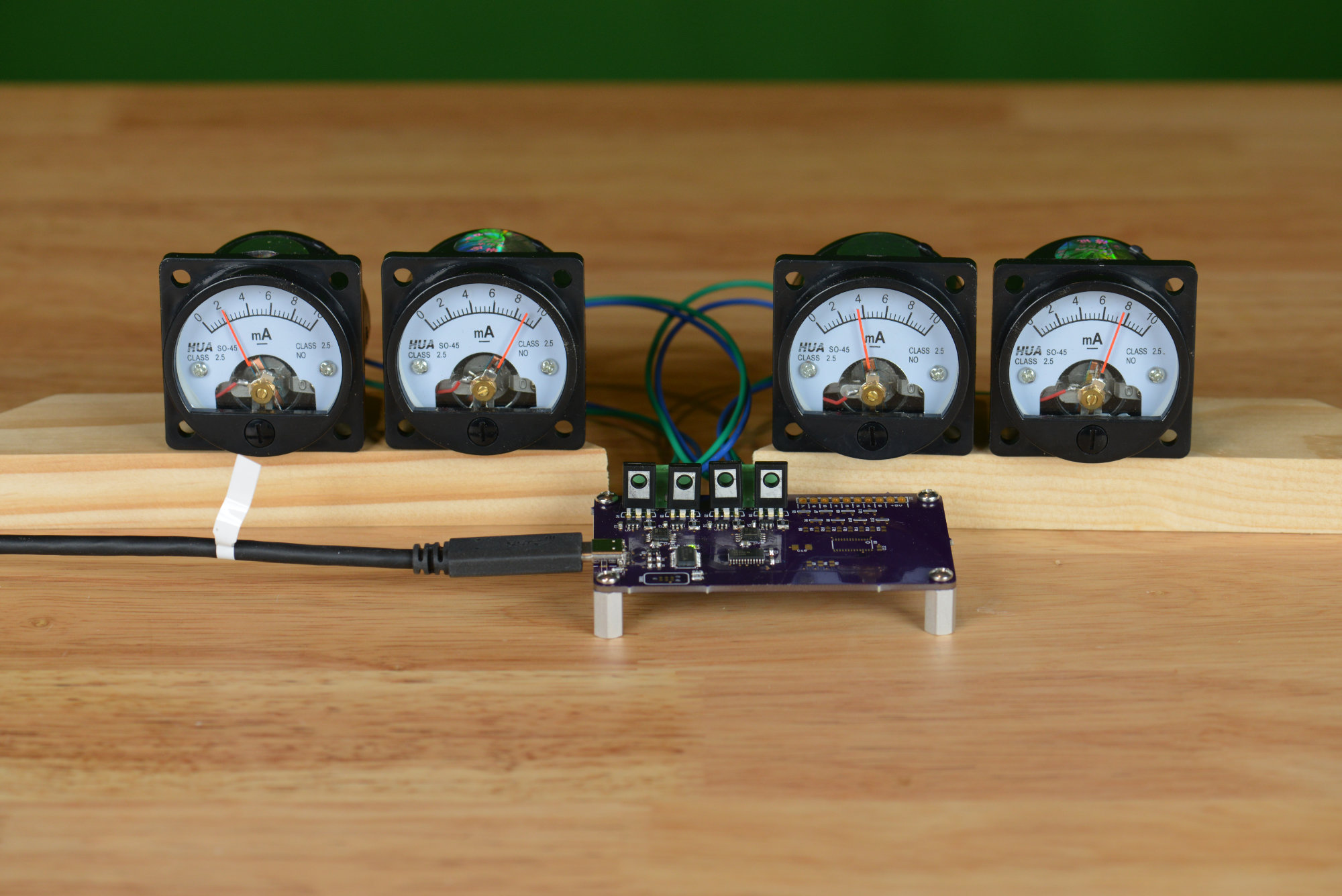
The completed USB analog panel meters project.
I’ve always liked the way these little HUA SO-45 analog panel meters looked, but, given the long lead times from China, I’ve never ordered a set. This fall, I changed my mind and finally decided to order a set. While they were in transit to the United States, I designed a small board to control them over USB using a Silicon Labs EFM8UB1 Universal Bee 8051-baeed microcontroller.
Past Analog Meter Driver Projects
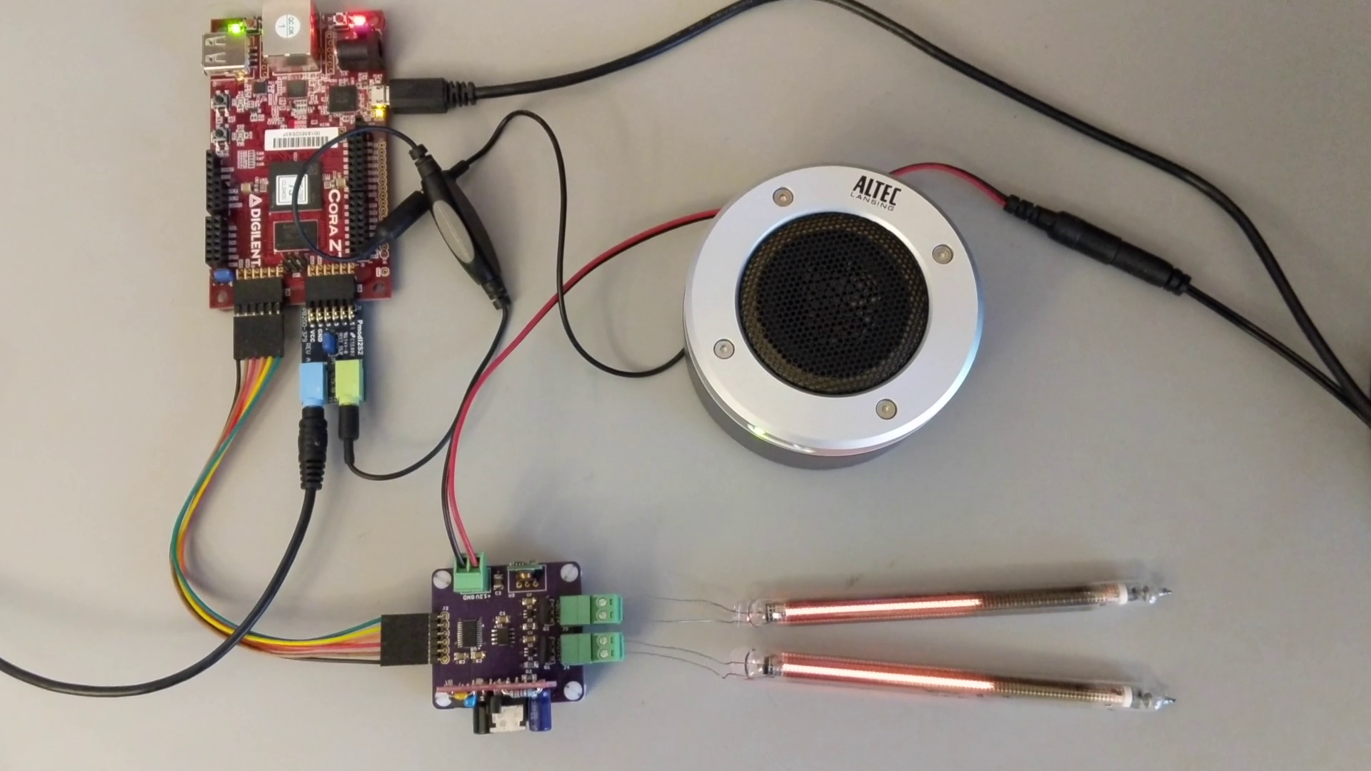
Nixie IN-9 linear bar graph display tubes.
I’ve designed a few analog meter projects in the past. The first was an IN-9 Nixie linear bargraph display that reacted to audio levels from music playing on my phone.
In this project, audio samples are digitized using a small ADC then the FPGA processes them into peak levels measured in dB down from the full scale input level. The peak levels are sent over SPI to a small DAC that forms a programmable current source that controls the current through the tube and thus the length of the displayed bargraph.
While researching this project, I discovered this great paper on controlling the IN-9 Nixie tubes. The programmable current source circuit I used to build my IN-9 audio meter is essentially the combination of Figure D and Figure F from this paper.
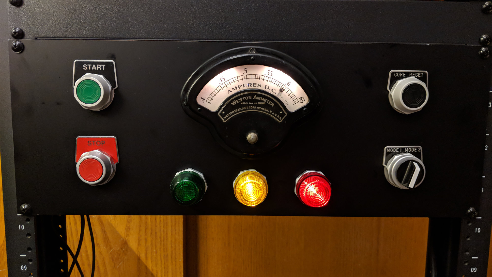
Another analog panel meter project using a vintage Weston panel meter.
Another analog meter project was a Halloween prop for a mad scientist’s laboratory that moves the needle back and forth on a vintage Weston analog panel meter. I was able to insert some small incandescent bulbs at the top of the meter to illuminate the meter. I’d like to do that on this project too if they’ll fit.
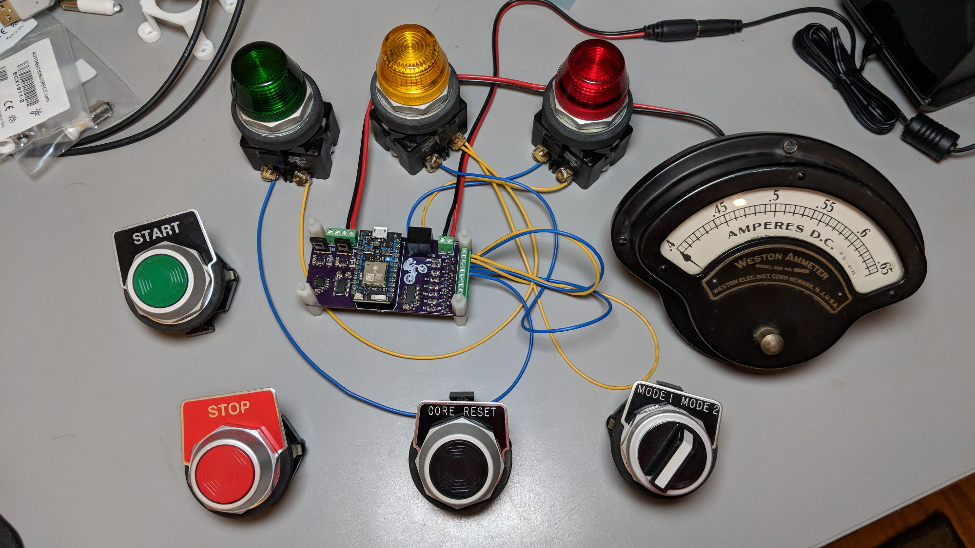
The driver circuit for the Weston analog panel meter.
For this project, I used the same programmable current source design as the Nixie project and added a PCA9685 16-channel, 12-bit PWM controller to control the panel lights and small bulbs added to the meter. As a side note, I pulled a shunt from this meter so that the full-scale current was around 50 mA instead of 650 mA.
Design Requirements
After mulling around this project some and revisiting the above projects, I decided on a feature list for the project:.
- There will be four analog panel meters.
- The analog panel meters would appear to the computer as a USB vendor-defined HID device class device.
- The project would use a Silicon Labs EFM8UB1 Uinversal Bee USB microcontroller.
- The project would use a USB 2.0 Type C connector for power and control.
- The project would use the same programmable current source design that was proven on the IN-9 Nixie and Weston vintage meter projects.
- If it was possible to hide some small LEDs to illuminate the meters, the project would use a PCA9685 PWM controller to control them.
EFM8UB1

EFM8UB1 functional block diagram from the data sheet.
The EFM8UB1 is an 8-bit 8051-based microcontroller featuring the usual assortment of microcontroller peripherals such as SPI and I2C as well as USB device capabilities. It runs from 3.3 volts and includes a built-in 3.3 volt voltage regulator and two built-in oscillators. The 48 MHz oscillator features USB clock recovery. A complete full-speed, 12 Mbps, USB device can be built using just this microcontroller and four decoupling capacitors.
The EFM8UB1 has 16 kB of FLASH and 2,304 bytes of RAM. It’s available in QFN-20, QFN-28, and QSOP-24 packages. I’m going to use the QSOP-24 because it’s easier for me to hand solder leaded packages than leadless packages. If your application outgrows the EFM8UB1, Silicon Labs has a migration path to the EFM8UB2 for applications needing more pins and memory or the EFM8UB3 for space-constrained applications that just need more memory.
For software development, the EFM8UB1 uses the Eclipse IDE and the Keil 8051 compiler in a software package called Simplicity Studio. Silicon Labs has negotiated a free license for the full version of the Keil 8051 compiler for use with their devices. The free, fully-optimizing compiler license gives the Silicon Labs EFM8 parts a significant advantage over devices from other manufacturers that require a monthly subscription to access the full versions of their compilers.
USB 2.0 Type C
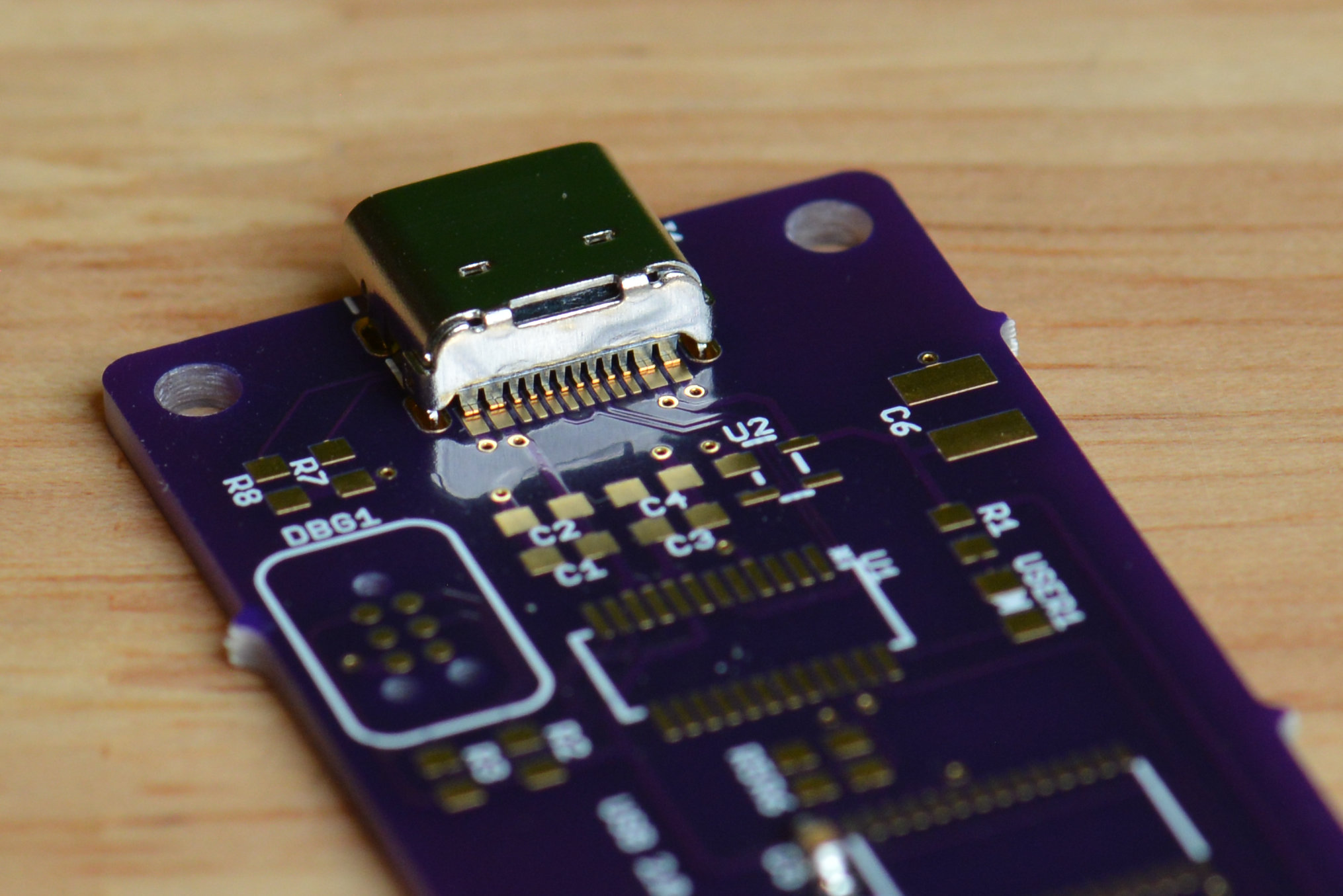
The rear of the USB 2.0 Type C connector. With enough flux and patience, it’s relatively easy to solder even with a 2.4 mm chisel tip.
I’ve been dreading moving my designs to USB Type C connectors. The USB 3.x versions of the connectors usually have two rows of surface mount pins and require a reflow oven or good skills with a hot air rework station to solder to boards.
Fortunately, there’s a lot of USB 2.0 Type C connectors that only include the pins required to implement the USB 2.0 and USB Type C PD standards. These connectors only have a single row of SMD pins and some surface mount or throughhole tabs for mechanical strength.
One of these connectors is the GCT USB4105-GF-A pictured above. It looks cramped but there’s plenty of room to get in there to solder the SMD leads to the pads. With enough flux and patience, I can solder these even using a 2.4 mm chisel tip. The toughest part of using this connector was figuring out how to construct plated slots for the retention tabs for fab at OSH Park using the Eagle PCB design package.
SPI for TLV5626
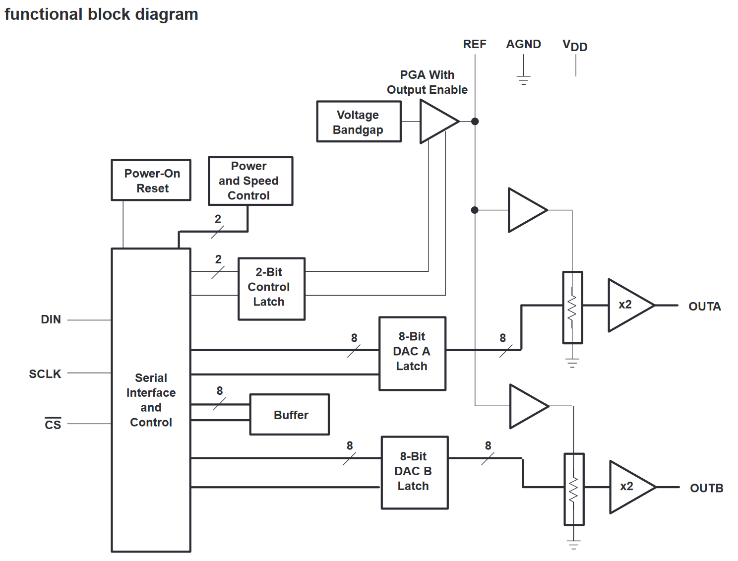
TLV5626 functional block diagram from the data sheet.
The heart of the programmable current source is the TLV5626 dual 8-bit DAC from Texas Instruments. It has a three-pin SPI interface: data, clock, and chip-select. Each of these DACs can control two meters. I bought four meters so I’ll need two DACs and two chip selects.
I2C for PCA9685

PCA9685 functional block diagram from the data sheet.
Finally, I included a PCA9685 16-channel, 12-bit PWM controller for controlling any LEDs I used to illuminate the meters. This part requires a two-wire I2C interface and an active-low output enable pin on the microcontroller.
Fixing the Pin Out
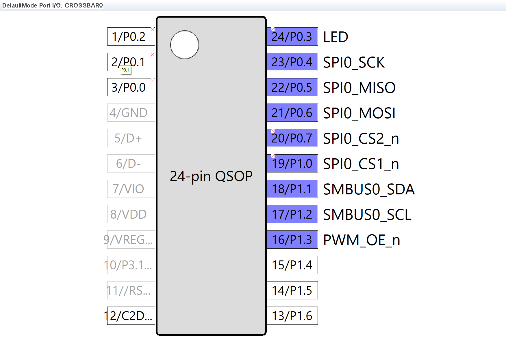
The final pin out for the project.
With the major design choices made, it was time to figure out how to connect the TLV5626 dual DAC and PCA9685 PWM controller to the EFM8UB1.
The EFM8UB1 includes a crossbar feature which permits “shoving” peripheral pins around the edges of the part. Unfortunately, it doesn’t support swapping the ordering of peripherals around the edges or swapping pins within a given peripheral. It’s mostly useful for moving peripherals to less congested areas of the board and leaving room for GPIO pins between peripherals.
The easiest way to configure the crossbar and determine the final location of the pins is to launch Simplicity Studio and try it out in its hardware configurator. For this design, I told the configurator to enable the SPI peripheral that will connect to the DACs, to enable the I2C peripheral that will connect to the PWM controller, and to skip pins P0.0, P0.1, P0.2, P0.3, P0.7, and P1.0.
In the screen capture from Simplicity Studio above, the small red X’s indicate skipped pins. I moved the SPI and I2C peripherals to the right side of the part since the left side of the part is congested on the board with the decoupling caps and USB interface. I then used three of the skipped pins as GPIOs for an LED and the two SPI chip selects.
When the hardware configuration is saved in Simplicity Studio, it generates code to initialize the crossbar, the ports, and the enabled peripherals. With the pin out of my design configured, it was time to create the schematic.
Schematic Design
The schematic has three pages. It’s not a complicated design, but it’s easier to explain on three separate sheets.
USB 2.0 Type C, Program/Debug, and Microcontroller
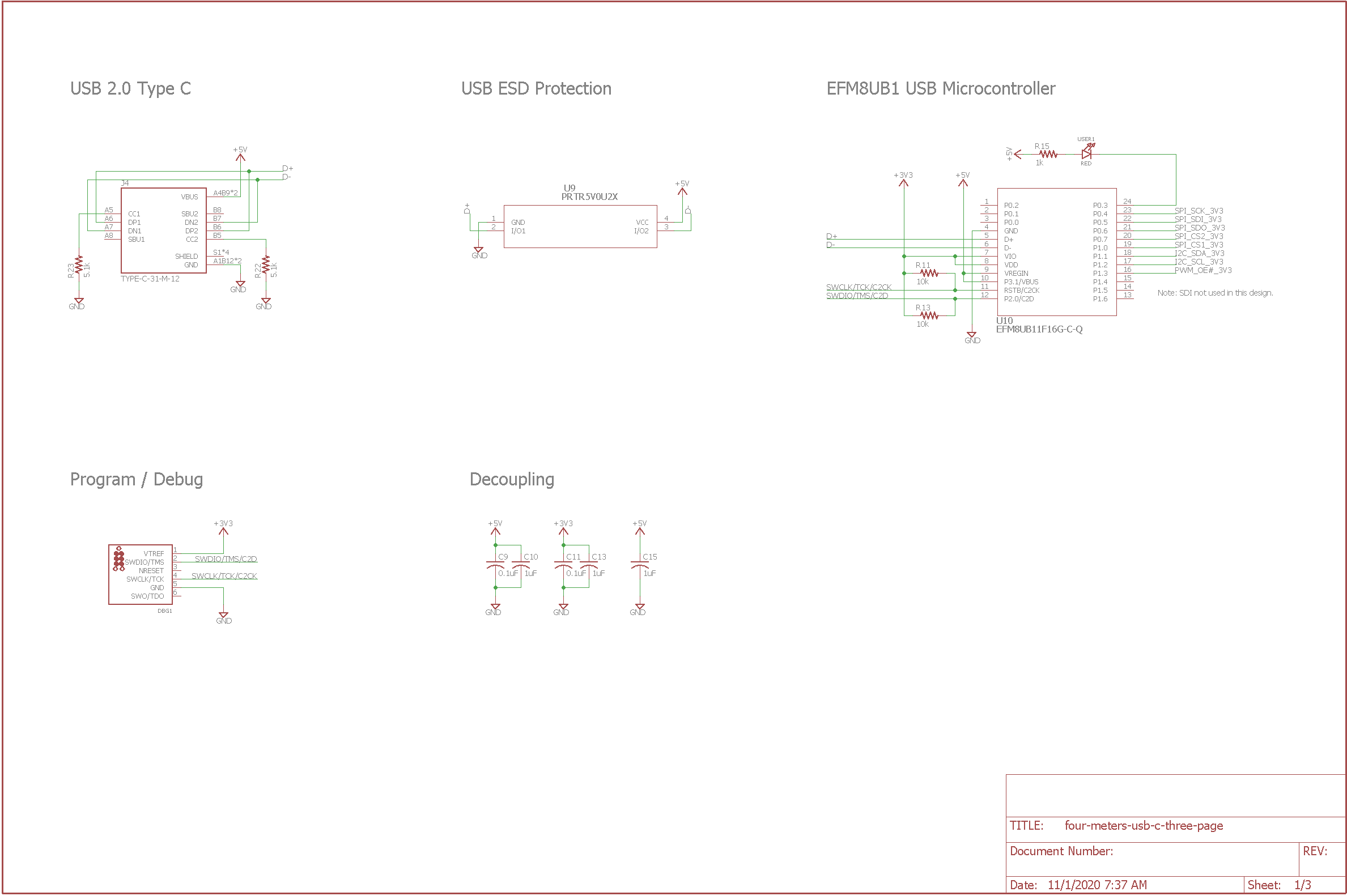
Schematic page 1 – USB 2.0 Type C, program/debug, and microcontroller.
The first schematic sheet is the EFM8UB1 and the parts required to get the microcontroller up and running as a USB peripheral. A USB 2.0 Type C connector connects to ESD protection diodes and the microcontroller.
For a USB device to enumerate properly when connected via a USB Type C to USB Type C cable to a USB Type C host, the CC1 and CC2 pins are required to be connected to ground through 5.1 k resistors. The specification explicitly requires a resistor for each pin. Trying to use a single resistor will not work as the Raspberry Pi Foundation figured out a while ago.
A programming connector, in this case a bunch of pads for a Tag-Connect cable, connects to the EFM8UB1’s two-wire programming interface. My programmer requires a reference voltage for the programming interface so 3.3 volts is also present on this connector along with the usual ground connection. Finally, there’s a 1 uF and a 0.1 uF capacitor in parallel on the 5 volt USB power lines at the EFM8UB1’s voltage regulator input pins and another set in parallel on the EFM8UB1’s regulated 3.3 volt output pins.
Analog Panel Meter Drivers
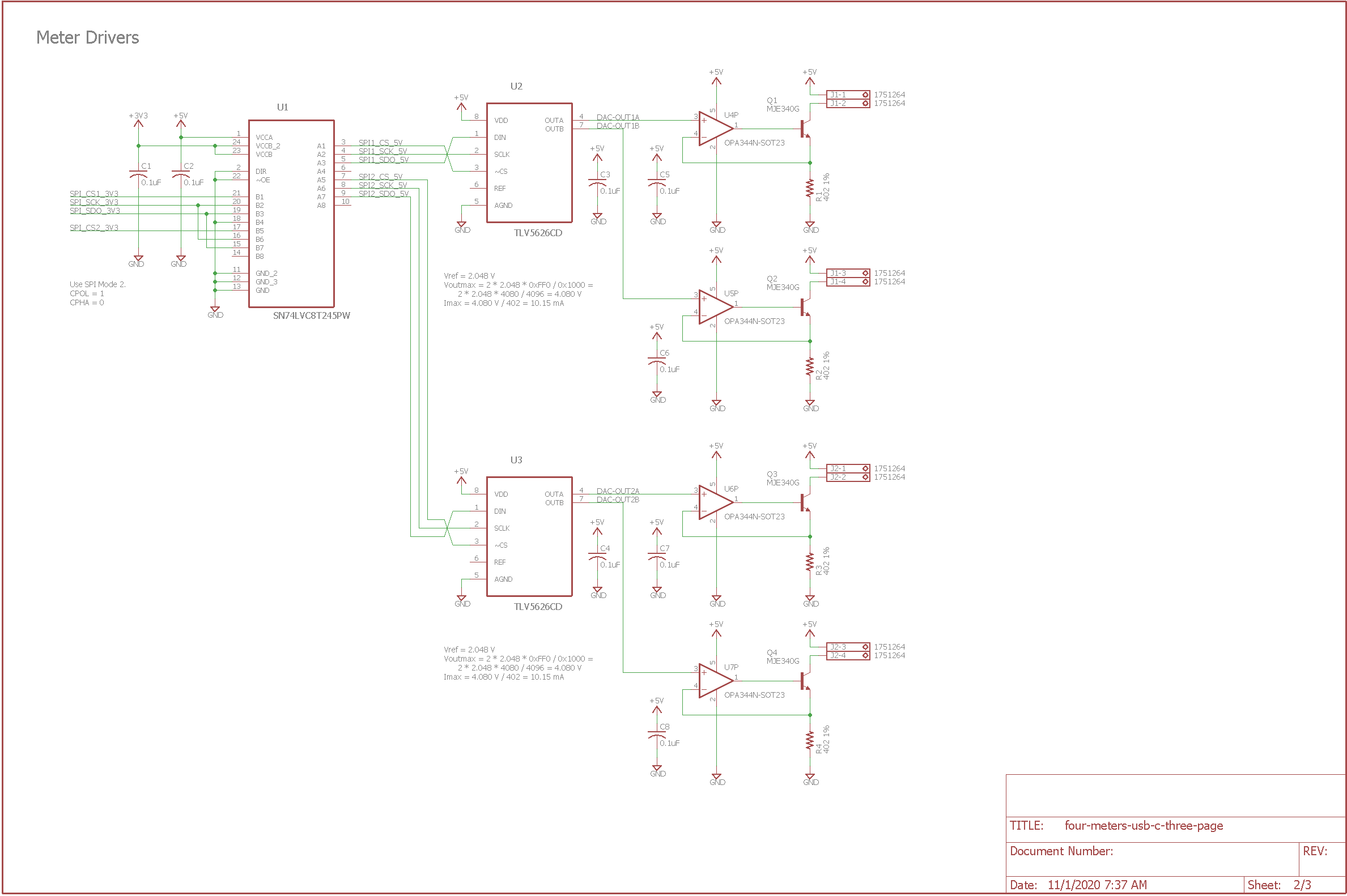
Schematic page 2 – analog panel meter drivers.
The second sheet of the schematic are the analog panel meter drivers. The circuit is a combination of Figure D and Figure F from this paper on driving IN-9 Nixie bar graphs. The 402 ohm resistors set the full-scale current output. Using the internal reference voltage of 2.048 volts with the DAC output set to its maximum of 0xFF, the output voltage will be 4.080 volts. The 402 ohm 1% resistors then set the maximum output current to 4.080 volts / 402 ohms = 10.15 mA. The detailed calculation is in the schematic. The op amps compensate for the base to emitter voltage of the transistors and permit a zero current output when the DAC output is set to 0x00.
The EFM8UB1’s internal 3.3 volt regulator can supply up to 100 mA for the device and system. Since the four meters can consume up to 10 mA each, I chose to run the DACs and op amps from the USB port’s 5 volt power rail instead of the EFM8UB1’s 3.3 volt regulator. This required a 3.3 volt to 5 volt translator on the SPI bus connections between the EFM8UB1 and the DACs. Fortunately, the DACs are write-only so only a single logic level translator IC was needed.
Backlight LED Drivers
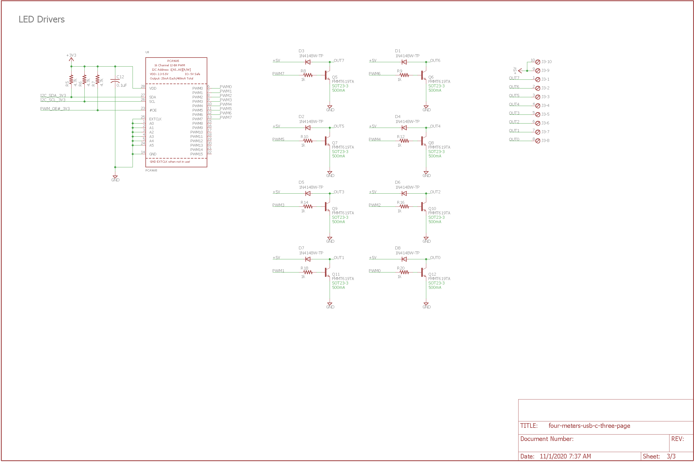
Schematic page 3 – backlight LED drivers.
The backlight LED drivers are a bunch of transistor switches connected to a PCA9685 16-channel, 12-bit PWM controller. When the PWM controller drives an output high, the connected transistor will turn on and sink current from its collector through to its emitter thus turning on the connected LED.
The PWM controller runs from the EFM8UB1’s regulated 3.3 volt supply. The LEDs are powered from the USB interface’s 5 volt supply. The PWM controller connects to the EFM8UB1 using the I2C interface. The I2C interface requires a 4.7k pull up resistor on its SCL and SDA lines to function.
The final connection back to the EFM8UB1 is the OE enable line for the PCA9685. When this line is low, the PCA9685 output is enabled and the LEDs can be illuminated. When high, the PCA9685 output is disabled and the LEDs will be turned off. This line is pulled high via a 4.7k resistor so that the LEDs remain off until the PCA9685 is initialized and the EFM8UB1 pulls the output enable line low.
Board Design
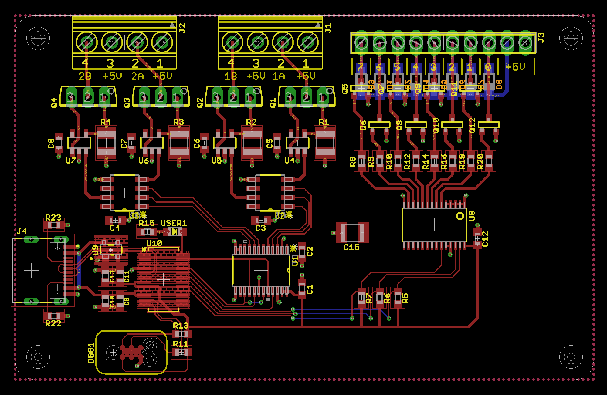
Finished board layout.
The board design is not too complicated. The USB D+/D- data lines are kept short and as parallel to each other as possible. The four required decoupling caps for the EFMUB1 are placed within millimeters of the microcontroller. The bottom of the board contains a filled ground plane and the top of the board contains a filled 5 volt layer. The 3.3 volt power for the B side of the level translator, the PCA9685, and the programming reference voltage is routed.
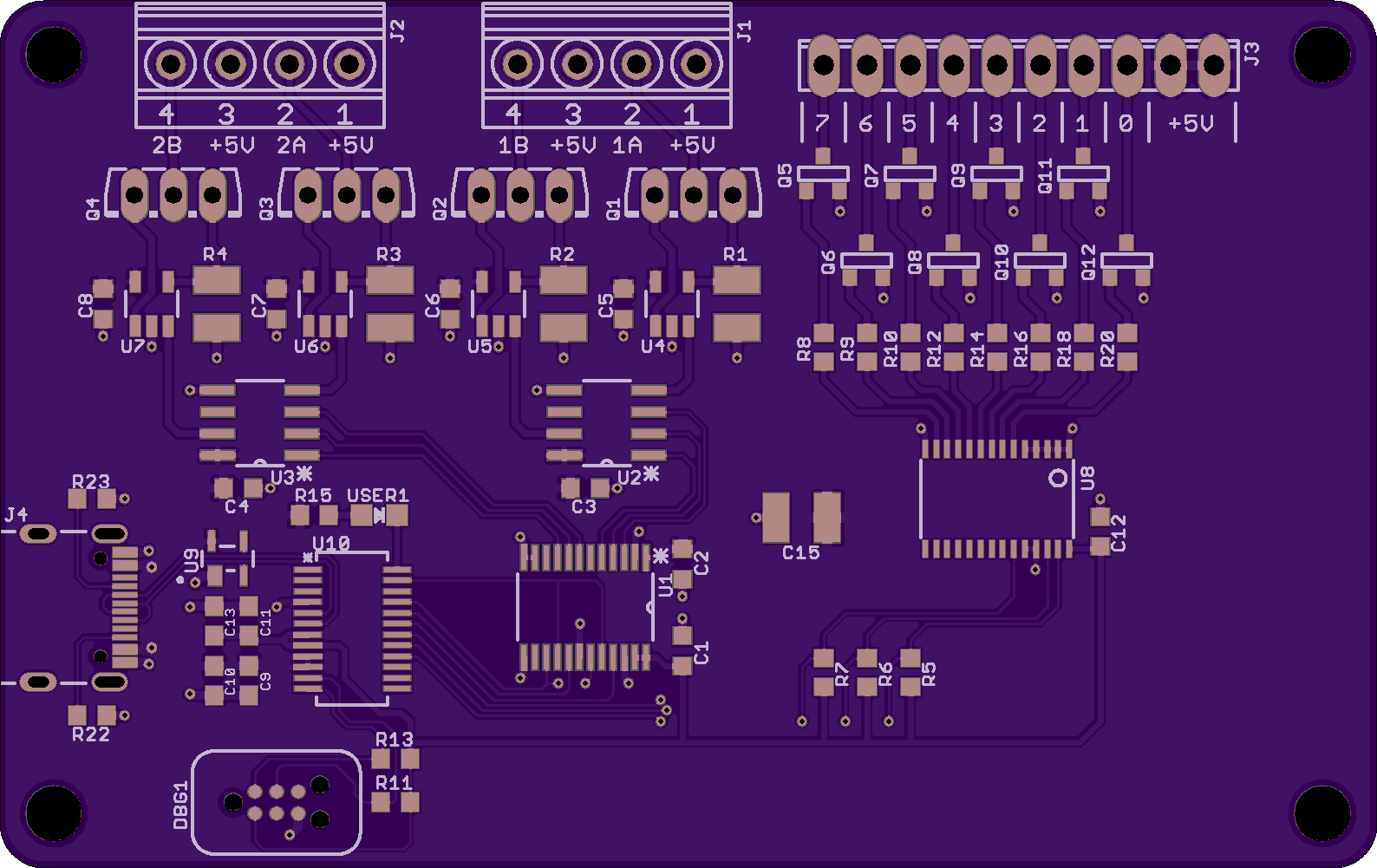
Board top preview.
After designing the board, I uploaded the Gerbers to OSH Park and use their tools to visualize the completed board. The top of the board is shown above. Note that the plated slots do render correctly so they have a reasonable chance of being fabricated correctly.
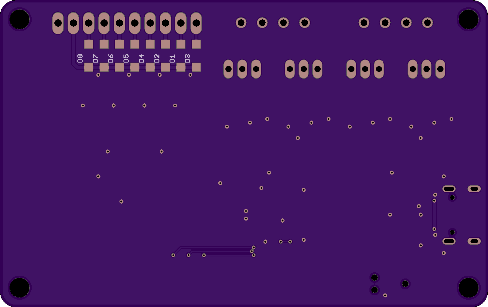
Board bottom preview.
Above is a render of the bottom of the board.

The blank board back from OSH Park.
Above is the fabricated board received back from OSH Park. The milled slots for the USB connector worked!
Assembly
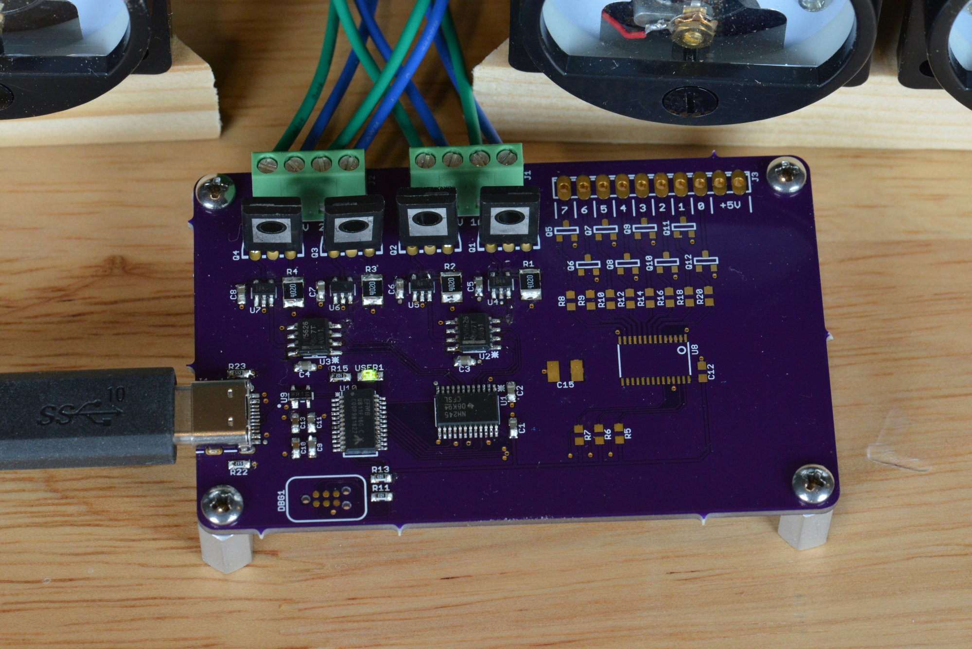
The assembled board.
While waiting for the boards, the four meters arrived from China. Upon examination, I noticed there really wasn’t room to place a small LED inside at the top to illuminate the scale and needle. An LED placed at the bottom would fit but would likely just cast shadows from the mechanism on to the scale. I decided to skip illuminating the meters and only assembled the EFM8UB1 and programmable current source portions of the board. I may in the future create another version of this board that is quite a bit smaller and without the PWM LED controller.
EFM8UB1 Software
For software development, I started with the USB keyboard, SPI, and I2C examples for the EFM8UB1-SLSTK2000A eval board. Once I was familiar with these examples, I created a new project using the hardware configurator that had the USB, SPI, and I2C and their required support peripherals enabled. I then modified the generated code as needed to support a vendor-defined USB device and pasted in the SPI and I2C code from the provided examples. I also added code for a timer.
Vendor-Defined USB Device
The files descriptors.h, config/usbconfig.h, and descriptors.c contain the bulk of the code that needs to be modified to create a vendor-defined USB device. The two header files are used to set the USB vendor ID, USB product ID, number and types of USB endpoints, and enable/disable various USB options like bus-powered vs self-powered, sleep/wake, power saving modes, etc.
The descriptors.c file needs to be modified extensively to create a vendor-defined USB device. I had to add an endpoint OUT descriptor, change the interface protocol to vendor defined, and create a report descriptor describing the OUT reports my device would use to set the analog panel meters.
I created a report descriptor with three OUT reports.
// HID Report Descriptor for Interface 0
SI_SEGMENT_VARIABLE(ReportDescriptor0[53],
        const uint8_t,
        SI_SEG_CODE) =
{

        0x06, 0x00, 0xFF,  // Usage Page (Vendor Defined 0xFF00)
        0x09, 0x01,        // Usage (0x01)
        0xA1, 0x01,        // Collection (Application)

        0x85, 0x01,        //   Report ID (1)
        0x95, 0x04,        //   Report Count (4)
        0x75, 0x08,        //   Report Size (8)
        0x26, 0xFF, 0x00,  //   Logical Maximum (255)
        0x15, 0x00,        //   Logical Minimum (0)
        0x09, 0x01,        //   Usage (0x01)
        0x91, 0x02,        //   Output (Data,Var,Abs,No Wrap,Linear,Preferred State,No Null Position,Non-volatile)

        0x85, 0x02,        //   Report ID (2)
        0x95, 0x02,        //   Report Count (2)
        0x75, 0x08,        //   Report Size (8)
        0x26, 0xFF, 0x00,  //   Logical Maximum (255)
        0x15, 0x00,        //   Logical Minimum (0)
        0x09, 0x01,        //   Usage (0x01)
        0x91, 0x02,        //   Output (Data,Var,Abs,No Wrap,Linear,Preferred State,No Null Position)

        0x85, 0x03,        //   Report ID (3)
        0x95, 0x03,        //   Report Count (3)
        0x75, 0x08,        //   Report Size (8)
        0x26, 0xFF, 0x00,  //   Logical Maximum (255)
        0x15, 0x00,        //   Logical Minimum (0)
        0x09, 0x01,        //   Usage (0x01)
        0x91, 0x02,        //   Output (Data,Var,Abs,No Wrap,Linear,Preferred State,No Null Position)

        0xC0,              // End Collection

        // 53 bytes
};
The first OUT report is four reports of eight bits each, aka four bytes. It’s used to set all the panel meters simultaneously. Byte 0 sets the level on the meter attached to output 1A, byte 1 sets 1B, byte 2 sets 2A, and byte 3 sets 2B. Each level ranges from 0 to 0xFF.
The second OUT report is two reports of eight bits each, aka two bytes. It’s used to set one meter at a time. The first byte contains the meter number to set from 0 to 3. The second byte contains the level to set on the meter from 0 to 0xFF.
The third OUT report is three reports of eight bits each, aka three bytes. It would be used to set the PWM level of the PWM controller’s selected channel if those devices were on the assembled board. The first byte contains the channel to set from 0 to 15 and the second and third bytes contain the 12-bit level to set from 0 to 4095. The level is right justified in the two bytes and sent MSB first.
Technically, the USB reports could be made more descriptive by using the correct fields for bits that are not used, but this is easier to make running changes to as you’re figuring out the code.
USB Callbacks
Once the USB interface code was configured and the report descriptor created, it was time to modify the USBD_XferCompleteCb in callbacks.c. USBD_XferCompleteCb is called whenever a USB IN report or USB OUT report is successfully transferred between the USB host and device. By default, the callbacks are called at interrupt time so care must be taken not to corrupt the operation of any peripherals that may be shared between the main line code and the interrupt code. Here’s my USBD_XferCompleteCb function.
// Technicaly SPI is fast enough I could do the updates at interrupt time
// without issues but I'm not sure I never want to be able to use the
// SPI in the main loop so I'm going to copy the data out of the USB
// rx packet and set a flag that lets the mainline code know it needs
// update the meters.

uint16_t USBD_XferCompleteCb(uint8_t epAddr, USB_Status_TypeDef status,
        uint16_t xferred, uint16_t remaining)
{
    uint8_t led;

    UNREFERENCED_ARGUMENT(status);
    UNREFERENCED_ARGUMENT(xferred);
    UNREFERENCED_ARGUMENT(remaining);

    if (epAddr == EP1OUT) {
        switch (rxBuffer[0]) {
            case 0x01:
                irqMetersUpdateFlags = 0x0f;
                irqMetersLevels[0] = rxBuffer[1];
                irqMetersLevels[1] = rxBuffer[2];
                irqMetersLevels[2] = rxBuffer[3];
                irqMetersLevels[3] = rxBuffer[4];
                break;
            case 0x02:
                if ((rxBuffer[1] >= 0) && (rxBuffer[1] <= 3)) {
                    irqMetersUpdateFlags = 1 << rxBuffer[1];
                    irqMetersLevels[rxBuffer[1]] = rxBuffer[2];
                }
                break;
            case 0x03:
                break;
        }
        USBD_Read (EP1OUT, rxBuffer, 64, true);
    }

    return 0;
}
Rather than attempt to access the SPI or I2C peripherals at interrupt time, I copy the received values to volatile variables then set a volatile flag telling the mainline code new values are available for sending via SPI to the DACs or via I2C to the PWM controller.
In the mainline of code, the flag is checked and, if set, cleared and the new values are sent to the DACs via the SPI:
        SFRPAGE_save = SFRPAGE;
        USB_DisableInts ();
        SFRPAGE = SFRPAGE_save;

        mainMetersUpdateFlags = irqMetersUpdateFlags;
        mainMetersLevels[0] = irqMetersLevels[0];
        mainMetersLevels[1] = irqMetersLevels[1];
        mainMetersLevels[2] = irqMetersLevels[2];
        mainMetersLevels[3] = irqMetersLevels[3];
        irqMetersUpdateFlags = 0;

        SFRPAGE_save = SFRPAGE;
        USB_EnableInts ();
        SFRPAGE = SFRPAGE_save;

        if (mainMetersUpdateFlags & 2) {
            // write DAC B value to DAC B and buffer
            dacData[0] = 0x00 | ((mainMetersLevels[1] >> 4) & 0x0f);
            dacData[1] = 0x00 | ((mainMetersLevels[1] << 4) & 0xf0);
            DacWrite (0, dacData);
        }

        if (mainMetersUpdateFlags & 1) {
            // write DAC A value and move buffer to DAC B simultaneously
            dacData[0] = 0x80 | ((mainMetersLevels[0] >> 4) & 0x0f);
            dacData[1] = 0x00 | ((mainMetersLevels[0] << 4) & 0xf0);
            DacWrite (0, dacData);
        }

        if (mainMetersUpdateFlags & 8) {
            // write DAC B value to DAC B and buffer
            dacData[0] = 0x00 | ((mainMetersLevels[3] >> 4) & 0x0f);
            dacData[1] = 0x00 | ((mainMetersLevels[3] << 4) & 0xf0);
            DacWrite (1, dacData);
        }

        if (mainMetersUpdateFlags & 4) {
            // write DAC A value and move buffer to DAC B simultaneously
            dacData[0] = 0x80 | ((mainMetersLevels[2] >> 4) & 0x0f);
            dacData[1] = 0x00 | ((mainMetersLevels[2] << 4) & 0xf0);
            DacWrite (1, dacData);
        }
Other Code
The main loop also contains some other code. At reset, all the meters are set to zero. Timer 2 is used to create a 100 Hz tick that runs various background tasks in the main loop. One of the background tasks is to blink the LED differently based on whether the EFM8UB1 is enumerated on the USB bus or not. A fast blinking LED means the device is enumerated. A slow blinking LED means the device is not enumerated. When the device is not enumerated (for example plugged into a USB charger instead of a computer), the meters sweep back and forth slightly out of sync and the LED blinks differently.
Linux USB HIDRaw
I tested the USB code using the Linux USB HIDRaw libraries.
UDEV Permissions
The first step is to make the analog panel meter controller available to non-root users by adding a .rules file to /etc/udev/rules.d. I called my file 46-hidraw.rules. Owner and group are root with 644 permissions. To this file, I added following lines:
#EFM8 USB Custom HID Device - EFM8UB1 Four Analog Panel Meters Controller
ATTRS{idProduct}=="000a", ATTRS{idVendor}=="4247", MODE="666", GROUP="plugdev"
The new rules will take effect the next time the USB device is enumerated. Disconnecting and re-connecting the analog panel meters controller is an easy way to force an enumeration.
HIDRaw Code
I based my HIDRaw code on the HIDRaw example at https://github.com/torvalds/linux/blob/master/samples/hidraw/hid-example.c.
The first step is to open the hidraw device:
fd = open(device, O_RDWR|O_NONBLOCK);
I assume there’s only one hidraw device on the system at /dev/hidraw0. A better way would be to use the udev libraries to search for analog panel meter controllers by vendor and product ID then possibly serial number to locate a specific analog panel meters controller.
Once the device is open, you can send OUT reports to the analog panel meters controller easily:
        printf ("Setting all meters to %d...\n", meterLevel);
        buf[0] = 0x01;          // report id
        buf[1] = meterLevel;    // meter 1 level (1A)
        buf[2] = meterLevel;    // meter 2 level (1B)
        buf[3] = meterLevel;    // meter 3 level (2A)
        buf[4] = meterLevel;    // meter 4 level (2B)
        res = write(fd, buf, 5);
This code sends an OUT report with report ID 0x01. The four bytes specified in the OUT report report descriptor then follow. In this case, they’re the levels to send to the four meters.
Testing and Accuracy
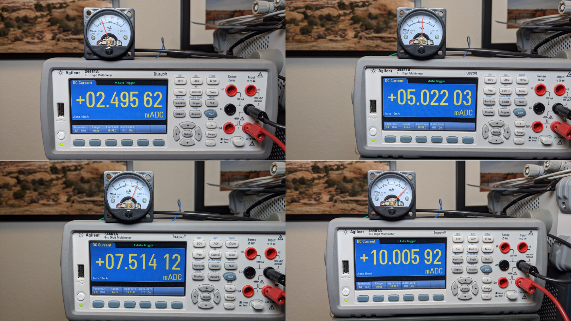
The HOA SO45 10 mA analog panel meters are more cute than accurate.
With both the embedded and Linux software completed, it was time to test the analog panel meter controller and the meters.
The first step was to test the DAC setting versus the output current using my Keysight 34461A bench DMM. When the DAC on output 1A was to set to 0x00, the output current measured 8.5 uA on the 34461A. When the DAC on output 1A was set to 0xFF, the output current measured 10.085 mA on the 34461A. At 0x80, the output current measured 5.061 mA. This is reasonable and actually pretty accurate considering the current range is set via a 402 ohm 1% resistor. If I were more motivated, I’d find an Ethernet cable and write some LXI code to cycle the DAC through all 256 codes while collecting current measurements and graph the linearity of the system.
Update: I found the code I wrote back in 2014 to make current measurements with the LXI/SCPI interface on the 34461A. I wrote a quick C program to set the DAC output to values from 0 to 255 inclusive then used LXI/SCPI to make a current measurement at each DAC output value with the 34461A. Below is a plot of DC current in mA versus DAC codes from 0 to 255. It’s pretty linear!
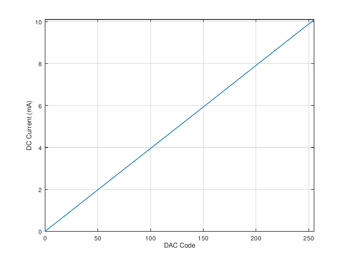
Current versus DAC code.
The next step was to test the accuracy of the meters versus my Keysight 34461 6.5 digit bench DMM. I set the DAC on output 1A to produce currents as close to 2.5 mA, 5 mA, 7.5 mA, and 10 mA as I could on the 34461A. I then photographed one of the HUA SO45 meters in series with the DMM and analog panel meter controller. The results are in the photo collage above. At 2.5 mA, the HUA is showing nearly 3 mA. At 5 mA, the HUA is showing a bit more than 5 mA. At 7.5 mA, the HUA is showing just over 8 mA. At 10 mA, the HUA is, well, off the scale.
Since I will ultimately use the meters to display real-world quantities such as temperature, time, fan speed, air quality, CO2 levels, etc. and I only care about where the meter points on the scale rather than the actual current flowing through the meter. I’ll compensate for the inaccuracies in software.
Bill of Materials
The bill of materials is reproduced below. It includes the parts for the untested and unused PCA9685 PWM controller and its output drivers.
| Qty | Parts | Description | Mfr | Mfr Part # | Dist | Dist Part # |
| 11 | C1, C2, C3, C4, C5, C6, C7, C8, C9, C11, C12 | CAP CER 0.1UF 50V X7R 0603 | KEMET | C0603C104K5RACTU | Digi-Key | 399-5089-1-ND |
| 2 | C10, C13 | CAP CER 1UF 16V X7R 0603 | KEMET | C0603C105K4RACTU | Digi-Key | 399-7847-1-ND |
| 1 | C15 | CAP CER 1UF 25V X7R 1210 | KEMET | C1210C105K3RACTU | Digi-Key | 399-8220-1-ND |
| 8 | D1, D2, D3, D4, D5, D6, D7, D8 | DIODE GEN PURP 100V 150MA SOD123 | Micro Commercial Co | 1N4148W-TP | Digi-Key | 1N4148WTPMSCT-ND |
| 2 | J1, J2 | TERM BLK 4POS SIDE ENT 3.5MM PCB | Phoenix Contact | 1751264 | Digi-Key | 277-5744-ND |
| 1 | J3 | TERM BLK 10P SIDE ENT 2.54MM PCB | On Shore Technology Inc. | OSTVN10A150 | Digi-Key | ED10567-ND |
| 1 | J4 | CONN RCPT USB2.0 TYPEC 5A | GCT | USB4105-GF-A | Digi-Key | 2073-USB4105-GF-ACT-ND |
| 4 | Q1, Q2, Q3, Q4 | TRANS NPN 300V 0.5A TO225AA | ON Semiconductor | MJE340G | Digi-Key | MJE340GOS-ND |
| 8 | Q5, Q6, Q7, Q8, Q9, Q10, Q11, Q12 | TRANS NPN 50V 2A SOT23-3 | Diodes Incorporated | FMMT619TA | Digi-Key | FMMT619CT-ND |
| 4 | R1, R2, R3, R4 | RES SMD 402 OHM 1% 1/2W 1210 | Vishay Dale | CRCW1210402RFKEA | Digi-Key | 541-402AACT-ND |
| 9 | R8, R9, R10, R12, R14, R15, R16, R18, R20 | RES SMD 1K OHM 5% 1/10W 0603 | Panasonic Electronic Components | ERJ-3GEYJ102V | Digi-Key | P1.0KGCT-ND |
| 3 | R5, R6, R7 | RES SMD 4.7K OHM 5% 1/10W 0603 | Panasonic Electronic Components | ERJ-3GEYJ472V | Digi-Key | P4.7KGCT-ND |
| 2 | R11, R13 | RES SMD 10K OHM 5% 1/10W 0603 | Panasonic Electronic Components | ERJ-3GEYJ103V | Digi-Key | P10KGCT-ND |
| 2 | R22, R23 | RES SMD 5.1K OHM 5% 1/10W 0603 | Panasonic Electronic Components | ERJ-3GEYJ512V | Digi-Key | P5.1KGCT-ND |
| 1 | U1 | IC TRNSLTR BIDIRECTIONAL 24TSSOP | Texas Instruments | SN74LVC8T245PW | Digi-Key | 296-34079-5-ND |
| 2 | U2, U3 | IC DAC 8BIT V-OUT 8SOIC | Texas Instruments | TLV5626CD | Digi-Key | 296-2311-5-ND |
| 4 | U4, U5, U6, U7 | IC OPAMP GP 1 CIRCUIT SOT23-5 | Texas Instruments | OPA344NA/3K | Digi-Key | 296-41475-1-ND |
| 1 | U8 | IC LED DRVR LIN DIM 25MA 28TSSOP | NXP USA Inc. | PCA9685PW,118 | Digi-Key | 568-11925-1-ND |
| 1 | U9 | TVS DIODE 5.5V SOT143B | Nexperia USA Inc. | PRTR5V0U2X,215 | Digi-Key | 1727-3884-1-ND |
| 1 | U10 | IC MCU 8BIT 16KB FLASH 24QSOP | Silicon Labs | EFM8UB11F16G-C-QSOP24 | Digi-Key | 336-3411-5-ND |
| 1 | D1 | LED GREEN CLEAR CHIP SMD | Kingbright | APHCM2012CGCK-F01 | Digi-Key | 754-1094-1-ND |
| 4 | — | HUA SO45 10mA Panel Meter | HUA | — | eBay/AliExpress | — |
Design Files
Design files for this project are in my usb-analog-panel-meters repository on GitHub.