
The lighted tree in the video above gets both the power and data for its RGB LED pixels using a single Ethernet cable. Power for the pixels is supplied from an Ethernet switch using the 802.3at PoE+ standard. Data for the pixels comes from software running on a PC that generates Art-Net packets at 40 Hz. Each Art-Net packet contains the RGB levels for all the pixels on the tree. Let’s take a closer look at the technical details and how this tree came into existence.
Motivation
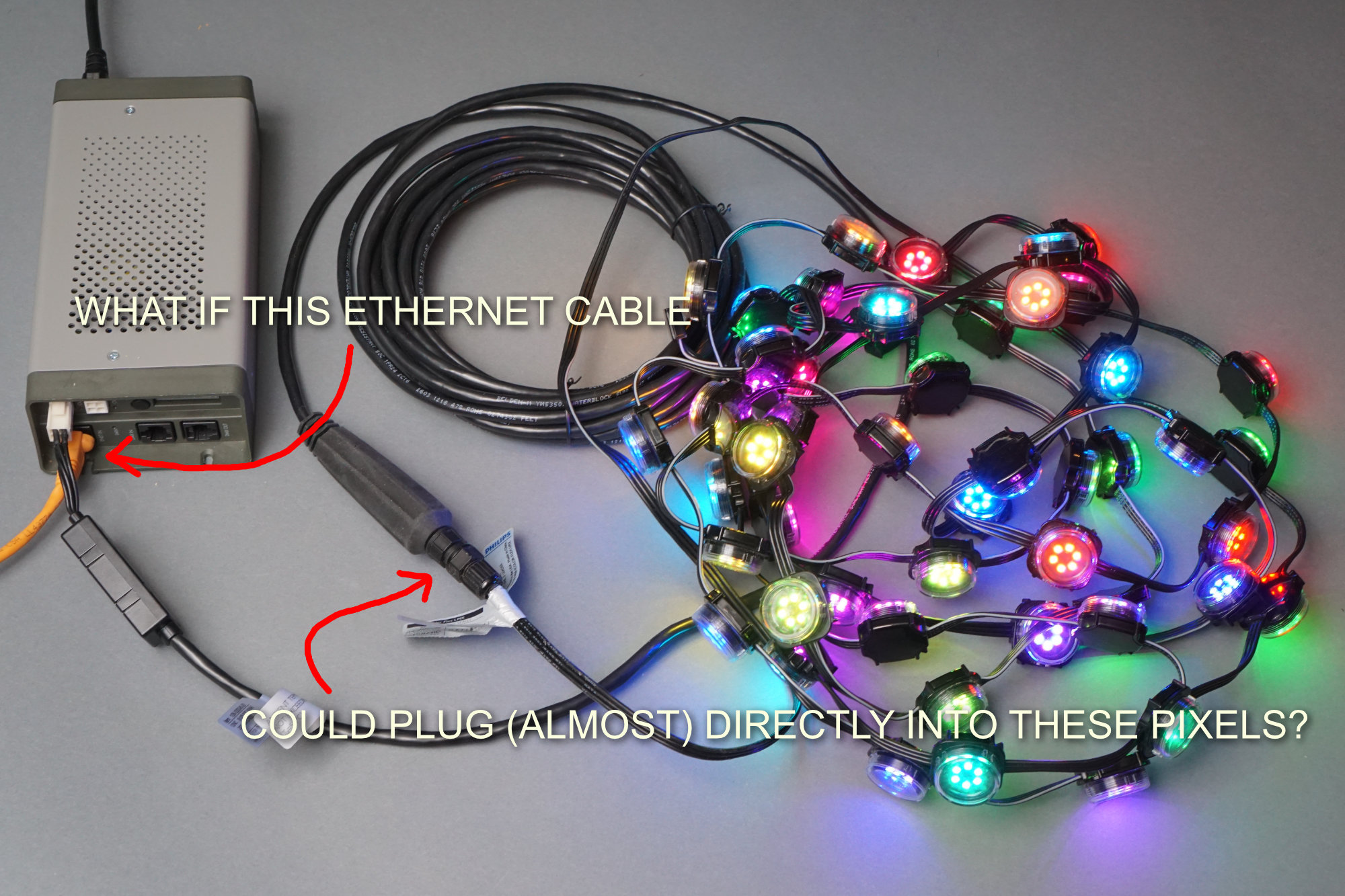
Philips Color Kinetics iColor Flex LMX setup with the AC power data supply, proprietary leader cable, and 50 pixels.
A few weeks ago, I wrote a post where I reversed engineered some Philips Color Kinetics iColor Flex RGB LED string lights. These lights require an AC power data supply that supplies 24 volts to power the pixels and transforms DMX or UDP packets of pixel data into the protocol used by the pixels. In addition to the power supply, the pixels require a proprietary leader cable to connect them to the power supply.
In a typical setup, you have to run AC mains power and Ethernet data to the power supply then run the leader cable to the pixels. To avoid having a large stack of power data supplies in larger setups, Color Kinetics makes a rack mount power supply that can power up to eight strings of lights. This rack mount power supply still requires a leader cable for each string of lights.
I’ve been wanting to build an 802.3af/at/bt Power over Ethernet design for a few years now and have always come up short on ideas and then it hit me, what if the Ethernet cable could connect closer to the pixels in the photo above? With a small box of electronics between the Ethernet cable and the connector on the end of the pixels, the pixels could receive both power and data from the Ethernet switch. No more AC mains wiring and no more proprietary leader cables.
802.3af/at/bt Power over Ethernet
Many Power over Ethernet schemes involve connecting the spare pairs in an Ethernet cable to an always-on 12 VDC or 24 VDC power supply. At the other end of the Ethernet wiring, the spare pairs are connected to a DC/DC converter that generates the voltages required by the device. This is fraught with problems and is not real Power over Ethernet!
802.3af/at/bt Power over Ethernet only supplies power to a device once a device detection and classification process completes. This process is a hardware handshake between the power sourcing equipment (PSE) and the powered device (PD). During the handshake, the PSE communicates its power sourcing capabilities to the PD and the PD communicates its power requirements to the PSE. If the PSE is capable of supplying the amount of power required by the PD, power is connected to the PD.
While the PD is powered, the PSE continuously monitors the current draw of the PD. If the current draw drops too low for too long, the PSE assumes the PD was disconnected and shuts down power to the PD. This process ensures power is only supplied to standards-compliant devices and only while those devices are connected.
In addition to the hardware handshake, Power over Ethernet can use Link Layer Discovery Protocol (LLDP) to communicate a PD’s power requirement to the PSE with greater resolution than permitted by the hardware handshake. For example, a device could complete the handshake indicating it is an 802.3at PoE+ compliant device but use LLDP to tell the connected switch it only requires 20 watts instead of the maximum 25.5 watts. This can potentially reduce the number of Ethernet switches required in large installations if the switches do not need to assume every device will always consume its maximum power.
| Property | 802.3af (802.3at Type 1) “PoE” | 802.3at Type 2 “PoE+” | 802.3bt Type 3 “4PPoE” | 802.3bt Type 4 |
|---|---|---|---|---|
| Power available at PD[note 1] | 12.95 W | 25.50 W | 51 W | 71 W |
| Maximum power delivered by PSE | 15.40 W | 30.0 W | 60 W | 100 W |
| Voltage range (at PSE) | 44.0–57.0 V | 50.0–57.0 V | 50.0–57.0 V | 52.0–57.0 V |
| Voltage range (at PD) | 37.0–57.0 V | 42.5–57.0 V | 42.5–57.0 V | 41.1–57.0 V |
| Maximum current Imax | 350 mA | 600 mA | 600 mA per pair | 960 mA per pair |
The table above is copied from the Wikipedia page on Power over Ethernet. It shows the 4 main types of Power over Ethernet and the amount of power each is capable of delivering to a PD. Also shown are the voltages a PD will see at its Ethernet jack based on the voltage supplied by the PSE, the maximum current draw of the PD, and the maximum resistance in 100 meters of Cat 3 (Type 1) or Cat 5 (Type 2 to 4) Ethernet cabling.
Type 1 and Type 2 PoE can use either the 10/100 Mbps data pairs or the 10/100 Mbps spare pairs for supplying power. It’s up to the switch to decide which set of pairs so the powered device must support using either set. Type 3 and Type 4 PoE use all four pairs for supplying power. All four PoE types work with all speeds of Ethernet, 10/100 Mbps as well as 1/2.5/5/10 Gbps.
For more information on Power over Ethernet, I highly recommend the Power over Ethernet Wikipedia page, section 7.4.1 of the Texas Instruments TPS2378 IEEE 802.3at PoE+ Interface data sheet (PDF), and the Silicon Labs Si3404/06x PoE-PD Controller Design Guide (PDF).
Feasibility and Scaling Back Ambitions
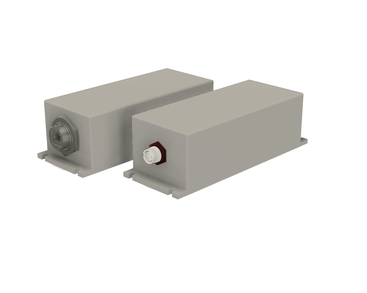
Artist’s depiction of two Ethernet to iColor Flex PoE power data supplies.
Getting back to my design, I pictured a small box with a waterproof Ethernet connector on one end and an Amphenol LTW waterproof connector for the pixels on the other end like the boxes in the artist’s rendering above. Inside the box would be 802.3af/at/bt classification circuitry, a power supply capable of delivering 62 watts at 24 volts, a microcontroller with Ethernet, and an FPGA to generate the Chromasic protocol data for the lights.
Referring to the chart of PoE capabilities in the previous section on standards-compliant Power over Ethernet, supplying 62 watts to the iColor Flex lights would require using 802.3bt Type 4 PoE and having an efficiency exceeding 87%. I felt this was certainly technically feasible but a bit too ambitious for my first PoE design. I also do not have an 802.3bt capable Ethernet switch yet. Time to scale back my ambitions a bit.
The next thought was to scale back to using iColor Flex MX pixels that require 22.5 watts at 7.5 volts. This could be powered using 802.3at PoE which is capable of delivering 25.5 watts to the powered device. This would require being over 88% efficient and I’d have to design a 7.5 volt wide input range buck converter too. I still felt this was a bit too ambitious.
A string of 50 RGB pixels on the left and a strip of 60 RGB pixels on the right.
The next step down in power consumption and complexity were the ubiquitous WS2812 RGB LEDs. Adafruit sells these in one meter strips of 60 RGB LEDs and Light-O-Rama sells these as five meter strings of 50 RGB pixels. Both of these consume 60 mA per bulb at 5 volts which is 0.3 watt per LED. A strip of 60 Neopixels consumes 18 watts maximum. The string of 50 from Light-O-Rama consumes 15 watts maximum.
15 and 18 watts easily falls within the 25.5 watt maximum for 802.3at PoE+. In addition, the WS2812 LEDs have significantly relaxed timing requirements compared to the iColor Flex LEDs. This allows the pixels to be controlled in software and eliminates the requirement for an FPGA to drive the pixels. Finally, the pixels run from 5 VDC. Since 5 VDC isolated switching DC/DC converter modules are common, I will not need to design a custom power supply as part of the project.
Over the course of a few hours, I talked myself down from building an 802.3bt 62 watt PD with an FPGA in a waterproof enclosure to building a much simpler proof-of-concept that uses 802.3at PoE+ for power and controls up to 60 WS2812 pixels in software. WS2812 pixels will be a great starting point for a project that can both power and control a string or strip of lights over Ethernet.
Electrical Isolation
The 802.3af/at/bt PoE standards require electrical isolation between the power interface and all user-accessible conductors including the frame ground. In a large commercial building, there could be 100 meters of Ethernet cable between the switch and the powered device with the result that the grounds at each end of the Ethernet cable have a large voltage difference between them. Without isolation, current would flow over the Ethernet cable which is both a safety issue and an electrical noise issue.
A lot of designs like PoE-enabled network cameras, Wi-Fi access points with internal antennas, and ceiling troffer LED lights have no user accessible conductors and therefore can use a non-isolated design. In this case, the enclosure and the lack of user-accessible conductors acts as the isolation required by the standard.
Other designs like Wi-Fi access points with external antenna connectors or building access controls with connections for locks and card readers require an isolated design. My design is going to have a connector for the WS2812 pixels so technically it requires an isolated design.
For both isolated and non-isolated designs, the 802.3 Ethernet standards require a transformer between the Ethernet jack and the Ethernet PHY. For isolated PoE designs, isolation is also required in the board layout, in the feedback loop in the power supply circuit, and in any status indicators between the PoE classification circuitry and the microcontroller. Isolated designs are therefore more complicated and more expensive than non-isolated designs.
Isolated designs do have an advantage during development and testing though. Programmers, debuggers, logic analyzers, oscilloscopes, and other test equipment can be connected to the isolated portions of the design without risk to the user or equipment. With a non-isolated design (or to debug the power interface side of an isolated design), you might need a battery-powered laptop to connect the debugger to the microcontroller, high-voltage differential probes for an oscilloscope, or a handheld oscilloscope with isolated input channels.
Design Requirements
Taking into account the selected pixels and the need for an isolated PoE design, here’s the basic list of requirements for my design:
- Use standards-compliant 802.3at PoE+ classification circuitry.
- Use less than 25.5 watts total power to stay within the 802.3at PoE+ power envelope.
- Use an isolated power supply design capable of supplying 20 watts at 5 volts. 15 to 18 watts will be available for the WS2812 pixels. Two watts will be available for the support circuitry including the microcontroller.
- Use transformers, optocouplers, and appropriate trace spacing to maintain isolation between the power interface circuitry and the remainder of the device.
- Use an Ethernet-capable microcontroller to reduce parts count and design complexity.
- Use easy to hand-solder SMD packages with no inaccessible pins, leads, or pads. One of these days, I’ll have to learn to solder/reflow DFN/QFN packages with exposed thermal pads, but I’m not there yet.
Selecting the PoE Controller
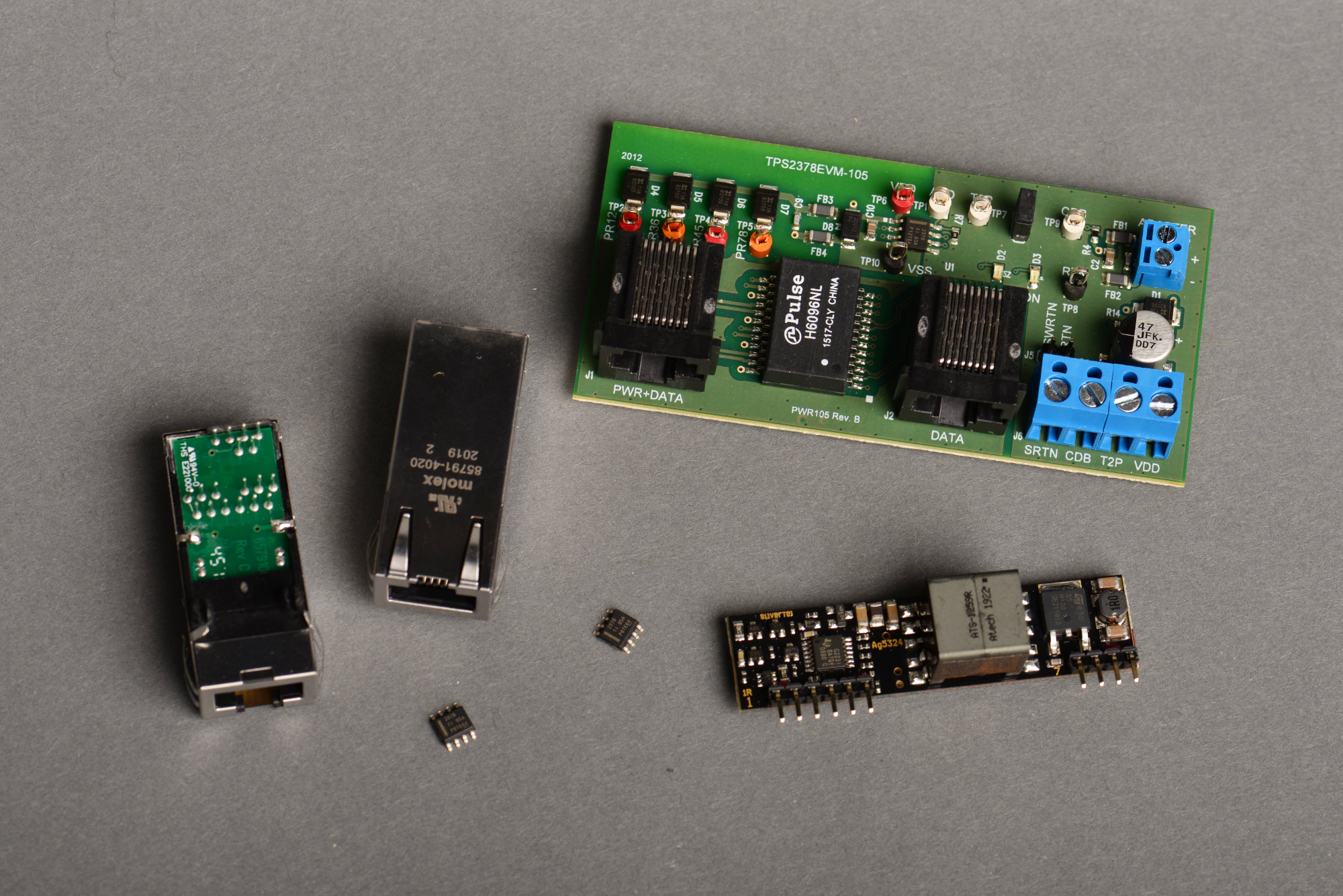
A bunch of different PoE+ PD components including two Molex PD jacks, two TI TPS2378 ICs, a TI TPS2378 evaluation board, and a Silvertel PoE+ PD 24 VDC module.
The 802.3af PoE standard was ratified in 2003 and the 802.3at PoE+ standard was ratified in 2009. The relative age of the standards means there’s tons of great PoE/PoE+ silicon and modules on the market.
Texas Instruments, Analog Devices, Microchip Technology, and Silicon Labs all make PoE PD controller silicon. All these chips handle classification. Many of these chips include integrated transistor switches to control power to the user’s circuitry. Some of these chips even include switch mode power supply controllers to step down the incoming voltage to the user’s required voltage.
Silvertel makes complete PoE modules capable of delivering from 13W to 99W to a PD. These modules handle classification, isolation, and include a DC/DC converter to step the input voltage down to a more usable 12 or 24 volts. Molex even makes Ethernet jacks with integrated magnetics and PoE/PoE+ classification circuitry. These jacks use the Microchip / Microsemi PD70200 controller.
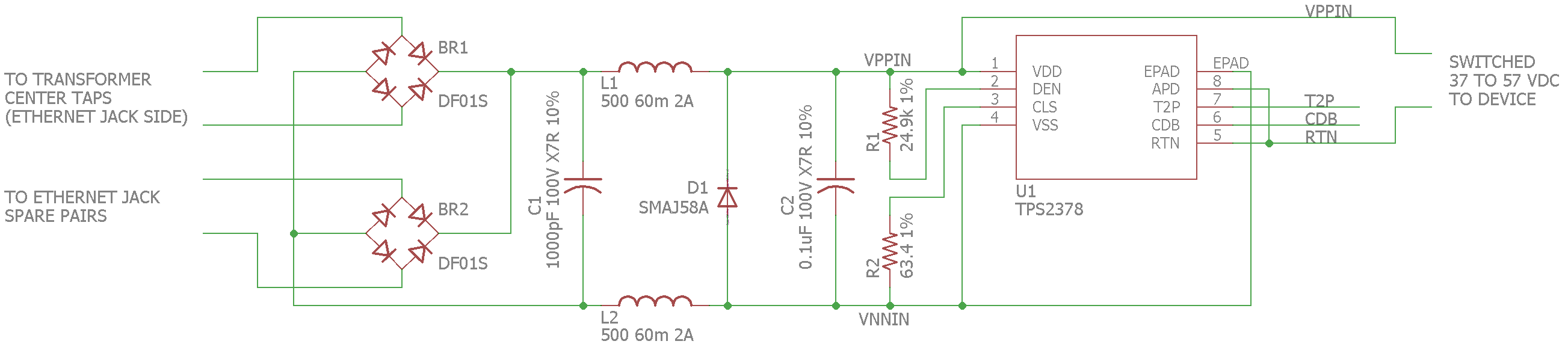
802.3at PoE+ powered device controller and classification circuit.
After reading datasheets for what felt like weeks, I settled on the TI TPS2378 802.3at PoE+ PD controller. It performs PoE+ detection and classification, includes an internal pass MOSFET with inrush current limiting, comes in a relatively easy to solder SOIC-8 package with an exposed thermal pad, and requires minimum external components.
The schematic above shows the basic circuit. Bridge rectifiers BR1 and BR2 rectify the voltage from the Ethernet jack since the input voltage is of unknown polarity. C1, L1, and L2 are an EMI/EMC filter. Zener diode D1 provides transient protection. C2 provides the minimum load capacitance required by the PoE specifications. R1 and R2 set the detection current and classification current respectively.
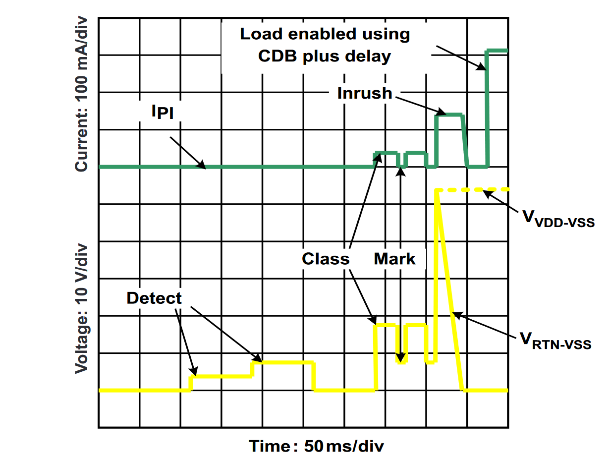
TI TPS2378 startup sequence from the datasheet.
Figure 19 from section 7.4.3 of the TPS2378 datasheet (reproduced above) shows the detection, classification, inrush current limiting, and startup sequence. When the input voltage is between 1.4 and 10.9 volts, the TPS2378 generates a detection signature. Once the PSE sees the detection signature, the PSE supplies a voltage between 10.9 and 22 volts. This is the classification phase and the TPS2378 generates a classification current between 36 and 44 mA to indicate it is a 802.3at PoE+ Type 2 / Class 4 device. For 802.3at this step is performed twice with a mandatory return to the detection current between each classification pulse.
Once classification is complete, the PSE supplies full power to the PD and the TPS2378 turns on the internal pass MOSFET but in an inrush current limiting mode. This limits the input current to about 140 mA and allows the bulk capacitors in the downstream power supply circuit to charge. Once the current through the pass MOSFET drops below 125 mA, inrush current limiting is turned off, the converter disable pin is de-asserted, and the user’s circuitry can run.
If 802.3at/PoE+ classification was successful, the T2P pin will be asserted and the user’s circuitry can run at full power. If 802.3at/PoE+ classification was not successful, the T2P pin will be de-asserted and the user’s circuitry must stay within the 802.3af PoE power envelope.
Selecting the Power Supplies
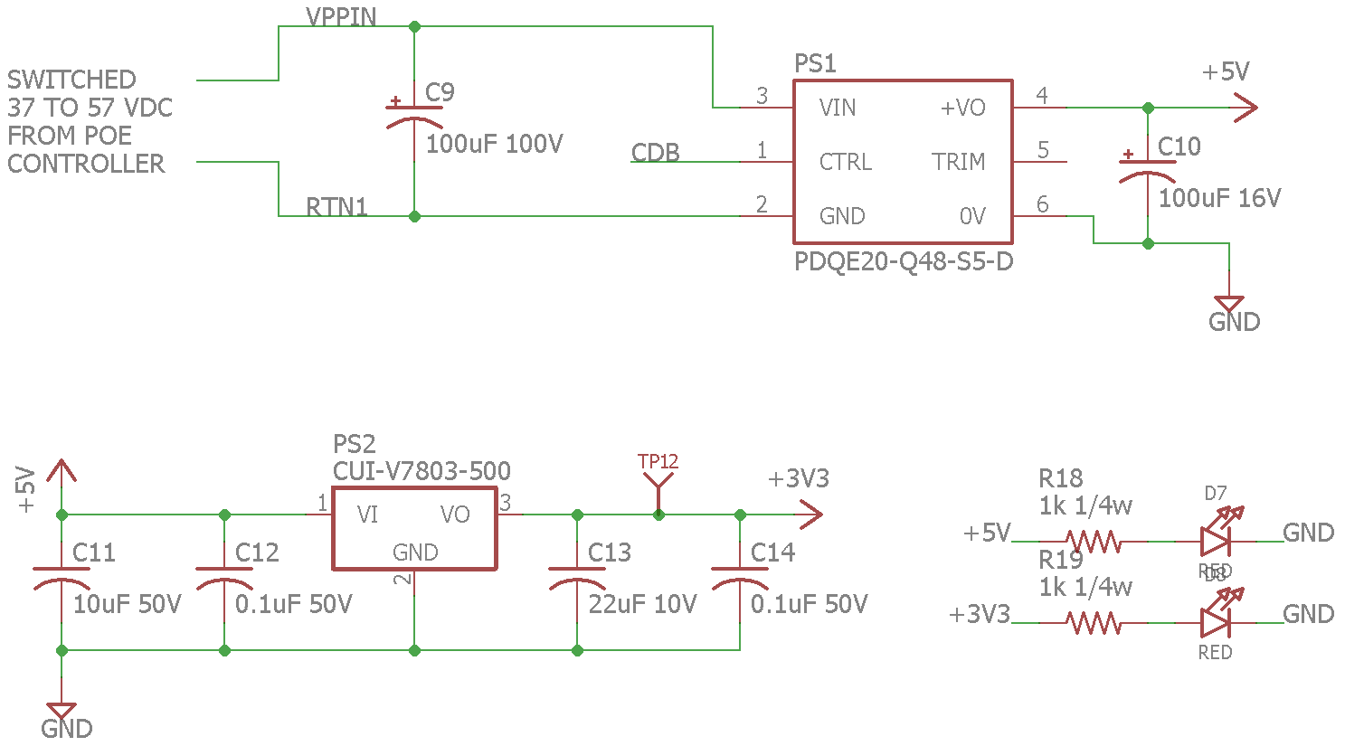
Isolated wide-input range to 5 VDC switching power supply module (top) and 3.3 VDC non-isolated switching power supply module (bottom).
The next step was to select an isolated DC/DC converter that has an input range of 37 to 57 VDC, a 5 VDC output, and a 20 watt power rating. The CUI PDQE20-Q48-S5-D meets these specifications. It has a nominal input voltage of 48 volts but works with a range from 18 to 75 volts. It is rated for 20 watts, is isolated, and has an efficiency of 90%. It comes in a 1″ by 1″ form factor module. The converter requires a 100 uF input capacitor and a 100 uF output capacitor for stable operation. It also has an active-low disable input that can be connected directly to the TPS2378’s CDB pin to keep the converter disabled until the bulk input capacitor is charged.
The microcontroller requires 3.3 VDC at about 250 mA. to operate. This is supplied by a CUI V7803-500 non-isolated switching regulator. It has an input range from 4.75 to 28 VDC and is connected to the output of the 5 VDC isolated converter. It requires a few capacitors to operate as well. I included a few LEDs to indicate the 5 VDC and 3.3 VDC power supplies are operational.
Selecting the Ethernet Microcontroller
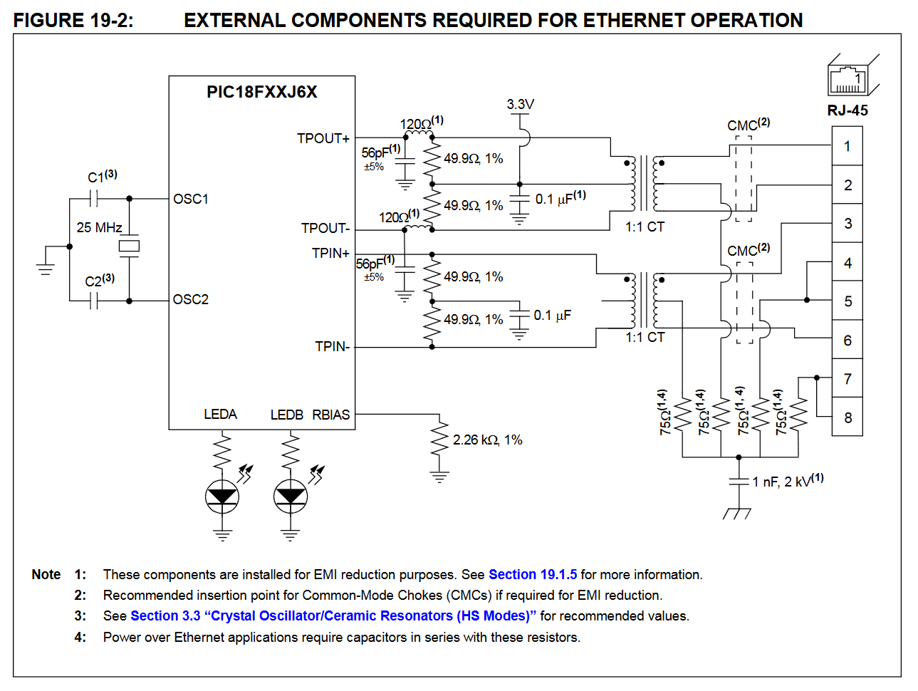
PIC18F67J60 minimal Ethernet circuit. Pay particular attention to Note 4 for Power over Ethernet applications.
The next step was to select a microcontroller to receive Art-Net UDP packets of pixel data and output the pixel data to the WS2812 LEDs. Most Ethernet microcontrollers only include Ethernet MAC functionality and require an external Ethernet PHY. The Microchip PIC18F67J60 microcontroller includes both an internal Ethernet MAC and PHY. This reduces the parts count and board area needed by the design.
The basic schematic from the data sheet is shown in the schematic above. I added some ESD protection circuitry as shown in the Microchip Ethernet of Everything reference design (PDF). The PIC18F67J60 is limited to 10 Mbps Ethernet but sixty 24-bit WS2812 pixels updated at 40 Hz only require 57,600 bits per second of data to operate.
Other Circuitry of Note
Here’s a brief examination of some of the other circuitry in the design.
Optically Isolated AT Classification Indicator
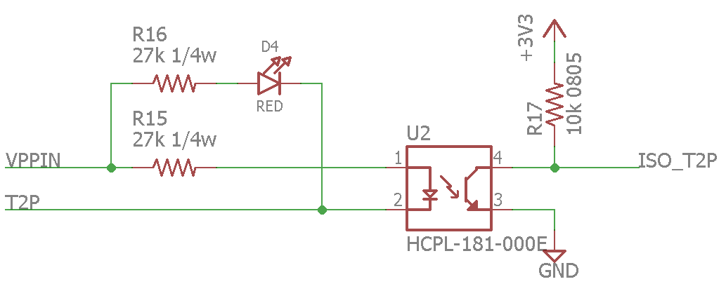
T2P flag isolation circuitry.
The TPS2378 asserts T2P low if 802.3at/PoE+ classification is successful. An optoisolator is used to isolate this signal and make it available to the microcontroller. When ISO_T2P is asserted low indicating the PD can draw up to 25.5 watts of power, the microcontroller can enable the WS2812 pixels.
3.3 VDC to 5 VDC Level Translator for WS2812 LEDs
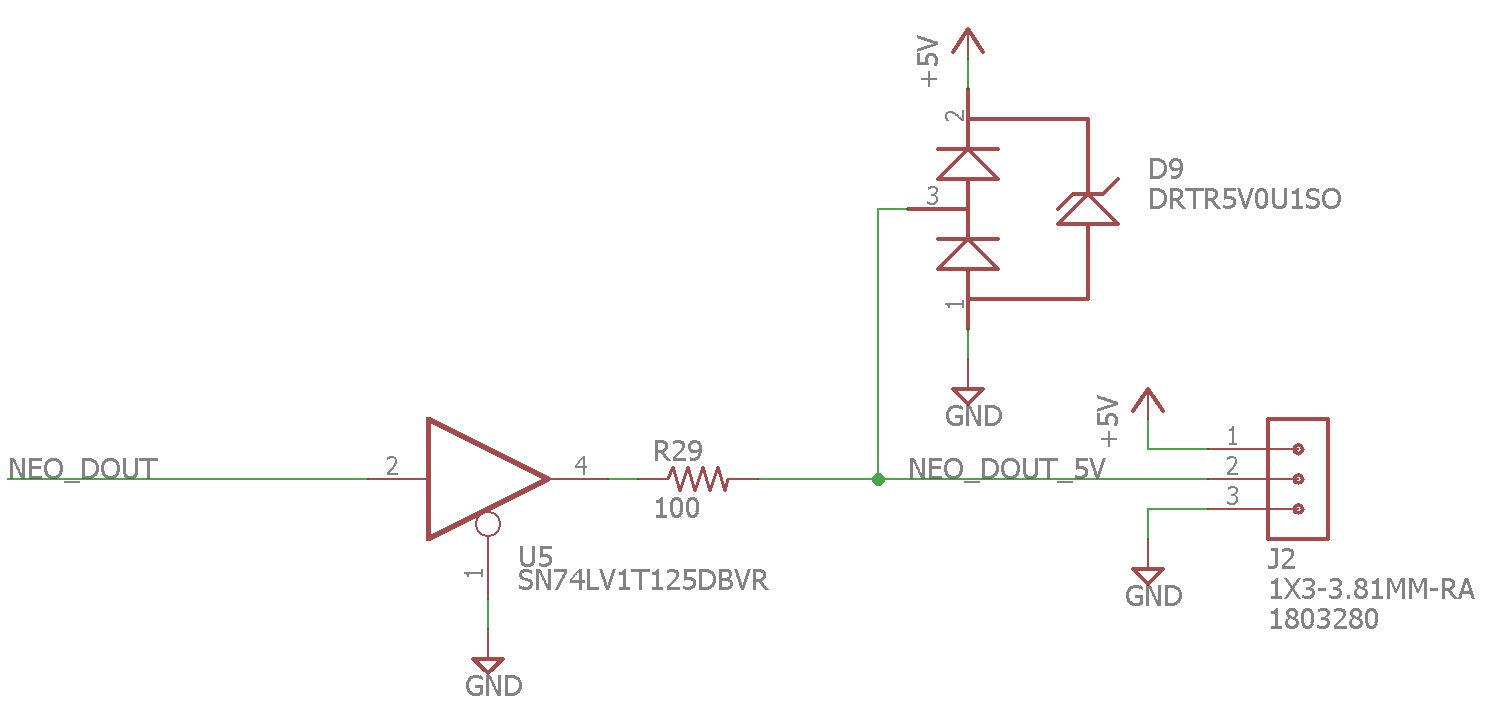
The 3.3 VDC to 5 VDC level translator and transient protection circuitry used to drive the WS2812 LEDs.
The microcontroller has 3.3 VDC outputs but the WS2812 LEDs have inputs referenced to 5 VDC. These generally work ok from 3.3 VDC but I added a Texas Instruments Little Logic single gate buffer to translate the 3.3 VDC output from the microcontroller up to 5 VDC. The resistor and diode array protect the microcontroller and buffer from transients on the WS2812 data line.
SiTime MEMS Oscillator
I’m using a SiTime MEMS oscillator to generate the 25 MHz clock for the microcontroller. This oscillator comes in a small but still easy-to-solder SOT23-5 package. Digi-Key programs them to the purchaser’s needed frequency on demand or you can buy a stock of blank parts and use the SiTime programmer to program them as needed.
Globally Unique MAC Address
Purchasing a block of MAC addresses for maker projects is not feasible. Instead I’m using a Microchip EUI-48 serial EEPROM that contains a pre-provisioned, globally-unique, and write-protected MAC address. The alternative for devices that will not be used outside your local network is to use a locally administered address from one of the locally administered address pools.
Finished Schematic
Here is the finished schematic. It’s two pages. Page 1:
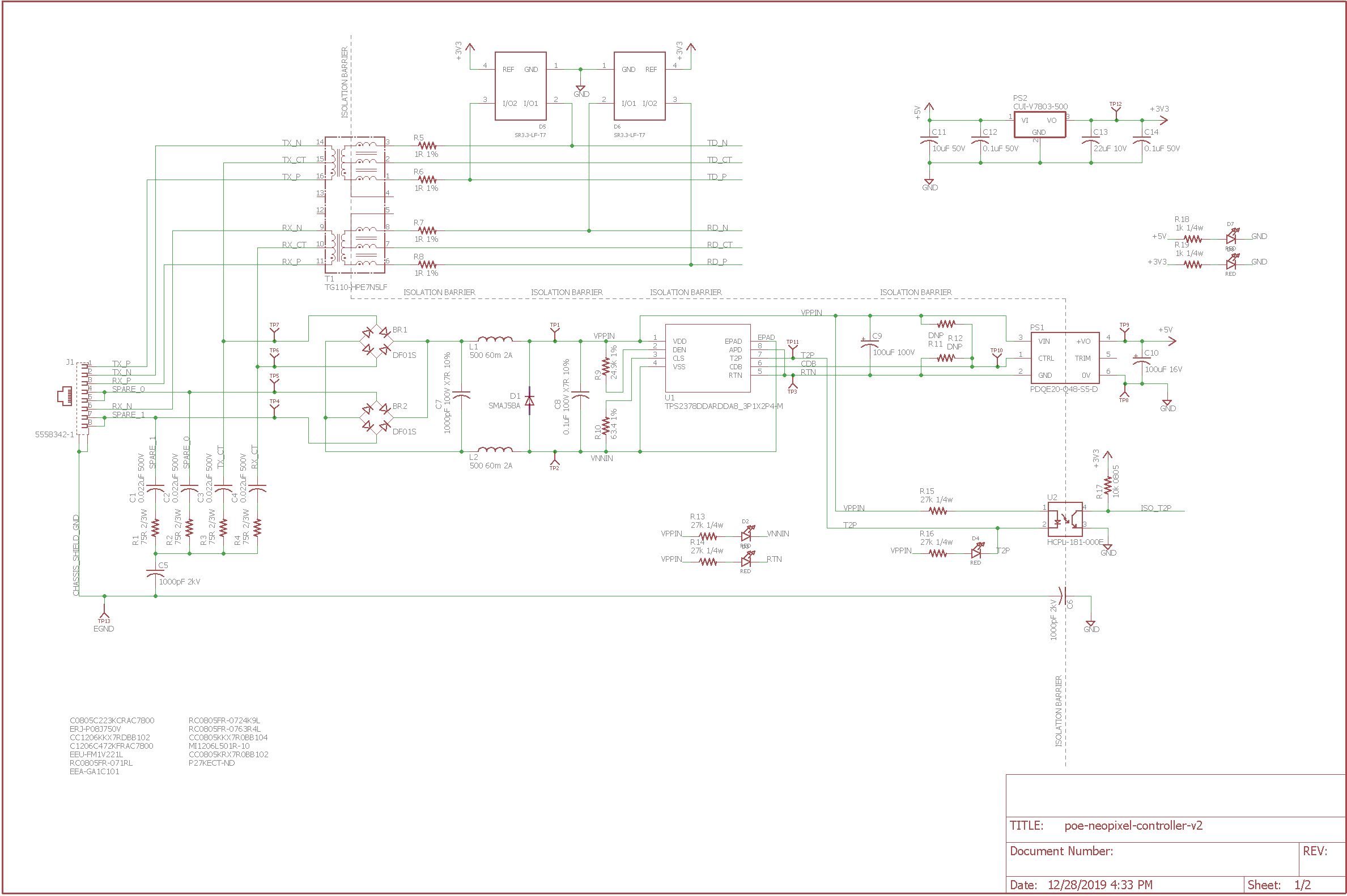
Finished schematic, page one.
Page 2:
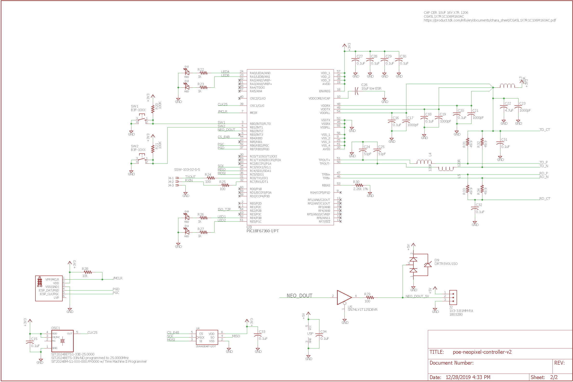
Finished schematic, page two.
Finished Board
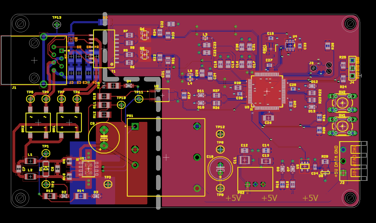
The finished board.
The image above shows the finished board. The thick dashed line shows the 56 mil space required to isolate the power interface circuitry on the left of the line from the user circuitry on the right of the line. The only components crossing the line are a filter capacitor rated for 2000 volts, the Ethernet magnetics, the T2P optocoupler, and the isolated DC/DC converter. All these parts provide DC isolation between the two halves of the board.
The next step was to upload the boards to OSH Park, check the renders, and order the boards.

OSH Park render of the top of the board.
The image above is an OSH Park render of the top of the board.
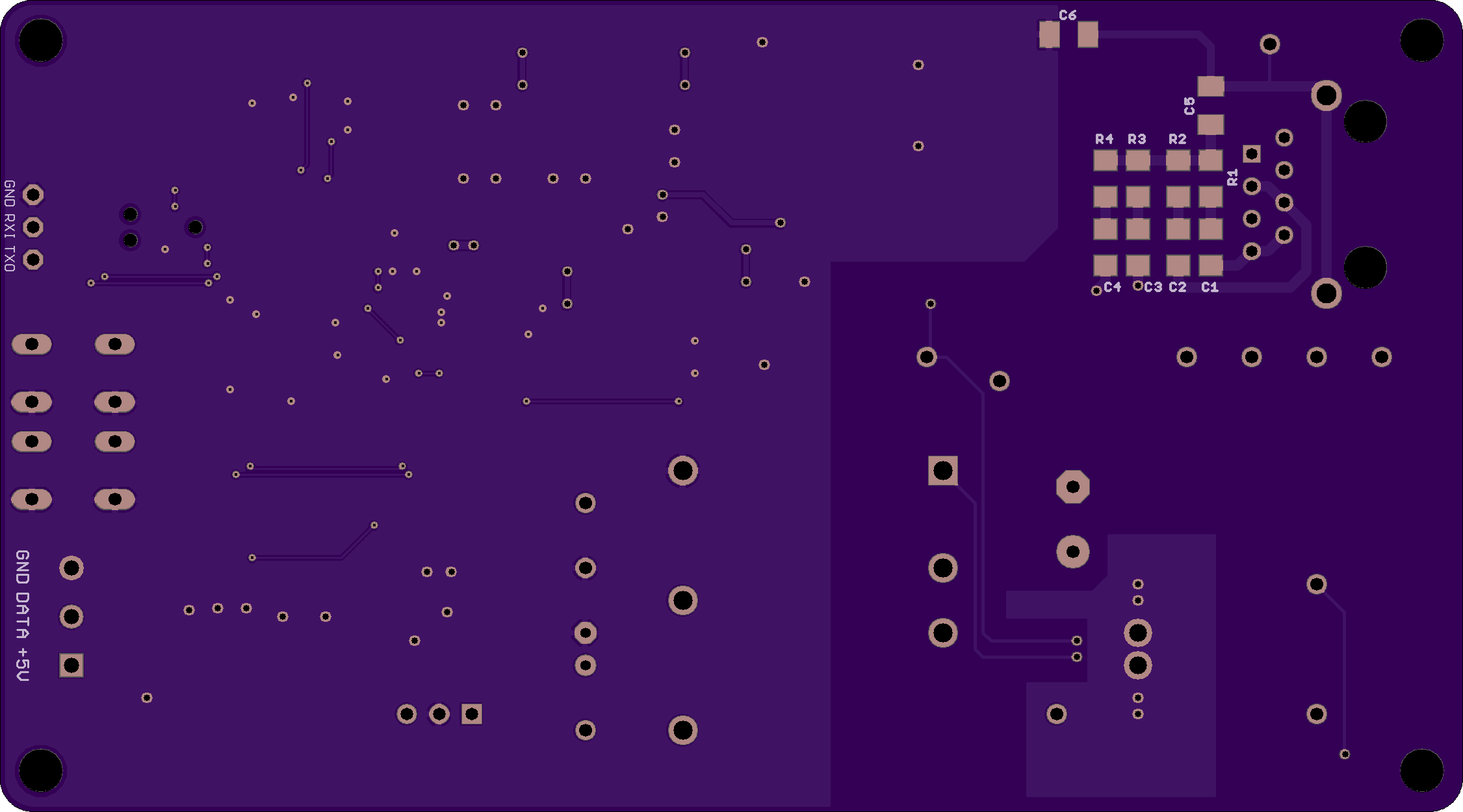
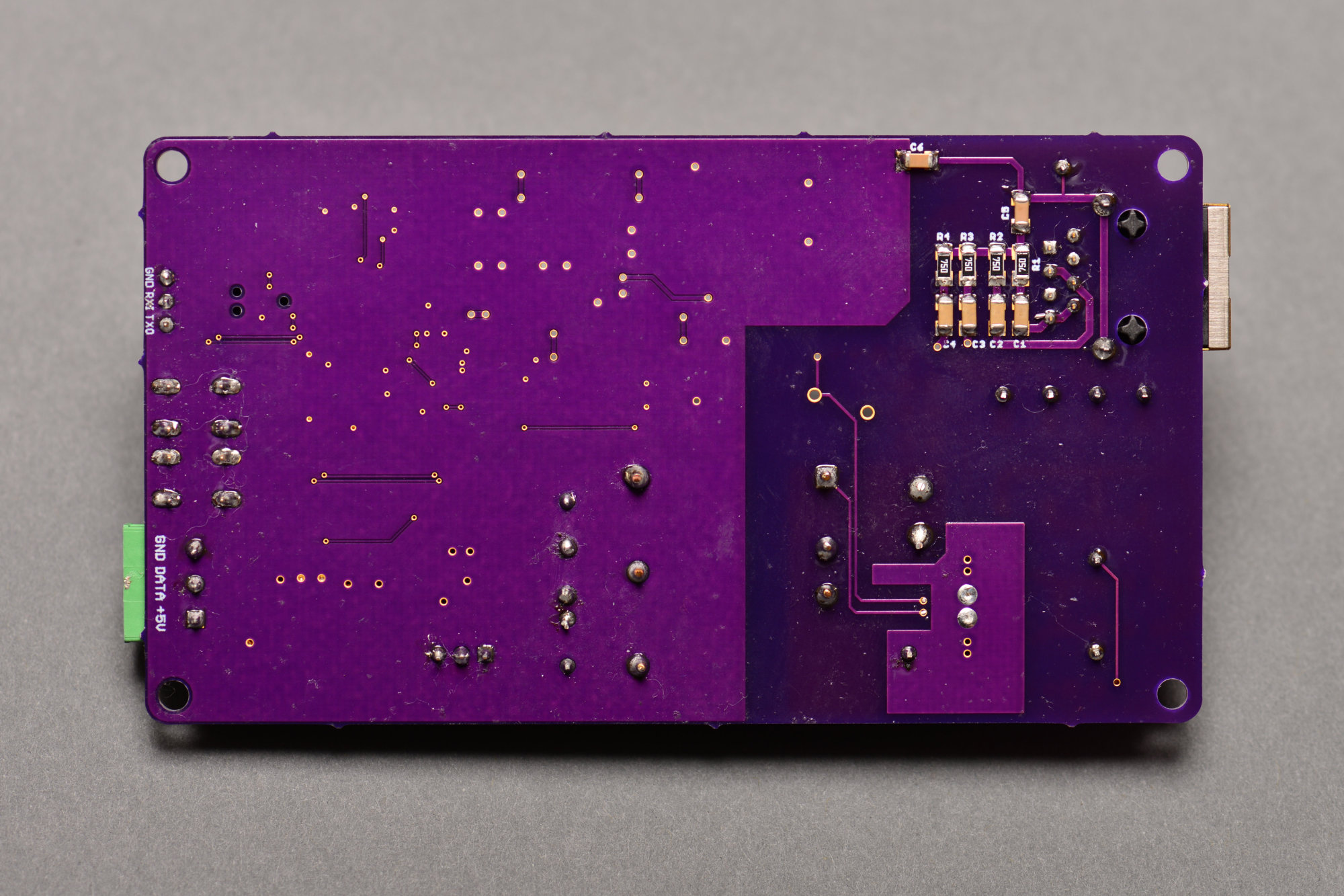
OSH Park render of the bottom of the board.
The image above is an OSH Park render of the bottom of the board.
Future Board Revisions
While these boards were being manufactured, a helpful Twitter user pointed out some revisions I could make to improve the EMI/EMC performance and some other minor changes to the board. Here’s the list of changes for future board versions:
- Change PIC18 ground traces to vias to 9 mil width.
- Change all other ground traces to vias to 20 mil width.
- Change the 3.3 V bridges between 3.3 V fills to 20 mil width.
- Change PIC18 pin 10 (VDDCORE) and 9 (GND) traces to 9 mil width.
- Move PIC18 pin 9 (GND) via to far side of capacitor. Make the trace 20 mil wide.
- Change TD_CT / filtered 3.3 V traces to 8 mil width between caps and PIC18.
- Changed 5V trace to a pour / fill.
- Increase separation of VPPIN to RTN to 25 mil per section 7.3.9 of TPS2378 data sheet.
- More vias on thermal pad.
- Use schottky diodes instead of bridge rectifiers for greater efficiency.
- Investigate routing 3.3 V power on top layer and adding a ground fill / pour on the top layer stitched to the bottom layer.
- Use jack with integrated magnetics or integrated magnetics and PD circuitry.
- Improve isolation / spacing between power interface circuitry and frame ground.
Software Development

The Olimex PIC-WEB board I used for software development while waiting for my boards.
While the boards were being manufactured, I started software development using an Olimex PIC WEB development board. The Ethernet hardware and software on this board is functionally identical to the Ethernet hardware and software on my board so it was a good platform to use for software development until my boards were available.
Microchip Code Configurator
I created a new PIC18F67J60 project in the MPLAB X IDE then used the Microchip Code Configurator (MCC) to generate the basic timer, EUSART, and TCP/IP Ethernet code for the project.
In the system tab, I enabled TMR1 interrupts, assigned the EUSART1 TX1 and RX1 pins, and configured an external 25 MHz clock on the primary OSC pins. In the libraries tab, I added the TCP/IP Lite library and enabled the UDP, DHCP, IPV4, ICMP, and ARP protocols. In the MAC tab, I selected ETHxxJ6x since I’m using the Ethernet MAC built into the device. I also configured a locally administered MAC address until I had an opportunity to enable the EUI-48 serial EEPROM. I added the TMR1 and EUSART1 peripherals then enabled the TMR1 interrupt to occur every 40 ms and the callback function to be called once per second. The EUSART was configured for 9600 bps and STDIO was redirected to USART. I clicked the generate tab to generate the initial code base.
Once the code was generated, I opened up main.c, removed the comments to enable interrupts, and added a call to Network_Manage () inside the while loop inside the main function. I built the project and downloaded it to the PIC-WEB board. It started running and eventually grabbed an IP address from my DHCP server. At this point I could ping the board but that’s about it.
Adding Art-Net UDP Receive
Next I added code to receive Art-Net packets over the network to the project. I created a udp_rx_artnet.h file with the following code:
#ifndef _UDP_RX_ARTNET_H
#define _UDP_RX_ARTNET_H

void UdpRxArtNetInit (void);
void UdpRxArtNetRecv (int16_t length);

#endif    //_UDP_DEMO_H
Then I created a udp_rx_artnet.c file with the following code:
#include <stdint.h>
#include "udp_rx_artnet.h"
#include "ws2812b.h"
#include "mcc_generated_files/TCPIPLibrary/udpv4.h"
#include "mcc_generated_files/TCPIPLibrary/tcpip_config.h"
#include "mcc_generated_files/pin_manager.h"


void UdpRxArtNetInit (void)
{
    // nothing to do here
}


void UdpRxArtNetRecv (int16_t length)
{
    uint8_t i;
    uint8_t leds;
    uint8_t r, g, b;

    if (length >= 18) {
        for (i = 0; i < 18; i++) {
            UDP_Read8 ();
        }

        length = length - 18;
        if (length > NUM_CHANS) {
            length = NUM_CHANS;
        }
        leds = length / 3;
        length = 3 * leds;

        for (i = 0; i < length; i+=3) {
            r = UDP_Read8 ();
            g = UDP_Read8 ();
            b = UDP_Read8 ();
            ledData[i+0] = gamma8[g];
            ledData[i+1] = gamma8[r];
            ledData[i+2] = gamma8[b];

        }

        for (; i < 150; i++) {
            ledData[i] = 0;
        }

        WS2812b_Write ();
        printf ("+");
        LATEbits.LATE4 = ~LATEbits.LATE4;
    }
}
It’s not the world’s most robust Art-Net receive code but it’ll work for proof of concept purposes. Next I added the UdpRxArtNetRecv function to the UDP callback table in MCC_Generated_Files/TCPIPLibrary/udpv4_port_handler_table.c:
const udp_handler_t UDP_CallBackTable[] = \
{
    {68, DHCP_Handler},
    {0x1936, UdpRxArtNetRecv},
};
Then inside main.c I added a call to UdpRxArtNetInit () to initialize the Art-Net receiver. I rebuilt the project and downloaded the code. (The first version of the code called printf’s to display the first few bytes of received RGB data rather than calling WS2812b_Write as shown in the listing above.) I then used my PC to generate Art-Net packets with 60 LEDs (180 channels) of data and send those to the PIC-WEB board. The printf’s showed the sent levels and it was time to move on to controlling the pixels.
Controlling the Pixels
In the past, I’ve used an FPGA to generate perfect WS2812 LED pixel timing. I did not use an FPGA on this project and instead used software to bit bang the protocol to the LEDs. Fortunately, the LEDs are quite tolerant to deviations from the timing specified in the data sheet and I had no issues controlling them.
The ws2812b.h header file:
#ifndef WS2812B_H
#define    WS2812B_H

#ifdef    __cplusplus
extern "C" {
#endif

#define NUM_LEDS 60
#define NUM_CHANS (3*NUM_LEDS)

#define WS2812b_LAT LATBbits.LB2
#define WS2812b_TRIS TRISBbits.TRISB2

void WS2812b_Init (void);
void WS2812b_Write (void);

extern uint8_t ledData[NUM_CHANS];
extern const uint8_t gamma8[256];

#ifdef    __cplusplus
}
#endif

#endif    /* WS2812B_H */
The ws2812b.c source file:
#include <stdint.h>
#include "mcc_generated_files/mcc.h"
#include "ws2812b.h"


const uint8_t gamma8[] = {
    0,  0,  0,  0,  0,  0,  0,  0,  0,  0,  0,  0,  0,  0,  0,  0,
    0,  0,  0,  0,  0,  0,  0,  0,  0,  0,  0,  0,  1,  1,  1,  1,
    1,  1,  1,  1,  1,  1,  1,  1,  1,  2,  2,  2,  2,  2,  2,  2,
    2,  3,  3,  3,  3,  3,  3,  3,  4,  4,  4,  4,  4,  5,  5,  5,
    5,  6,  6,  6,  6,  7,  7,  7,  7,  8,  8,  8,  9,  9,  9, 10,
   10, 10, 11, 11, 11, 12, 12, 13, 13, 13, 14, 14, 15, 15, 16, 16,
   17, 17, 18, 18, 19, 19, 20, 20, 21, 21, 22, 22, 23, 24, 24, 25,
   25, 26, 27, 27, 28, 29, 29, 30, 31, 32, 32, 33, 34, 35, 35, 36,
   37, 38, 39, 39, 40, 41, 42, 43, 44, 45, 46, 47, 48, 49, 50, 50,
   51, 52, 54, 55, 56, 57, 58, 59, 60, 61, 62, 63, 64, 66, 67, 68,
   69, 70, 72, 73, 74, 75, 77, 78, 79, 81, 82, 83, 85, 86, 87, 89,
   90, 92, 93, 95, 96, 98, 99,101,102,104,105,107,109,110,112,114,
  115,117,119,120,122,124,126,127,129,131,133,135,137,138,140,142,
  144,146,148,150,152,154,156,158,160,162,164,167,169,171,173,175,
  177,180,182,184,186,189,191,193,196,198,200,203,205,208,210,213,
  215,218,220,223,225,228,231,233,236,239,241,244,247,249,252,255 };

uint8_t ledData[NUM_CHANS];


void WS2812b_Init (void)
{
    WS2812b_LAT = 0;
    WS2812b_TRIS = 0;
}


void WS2812b_Write (void)
{
    uint8_t i, j, a;

    INTERRUPT_GlobalInterruptDisable();
    INTERRUPT_PeripheralInterruptDisable();

    for (i = 0; i < NUM_CHANS; i++) {
        a = ledData[i];

        // 7
        if (a & 0x80) {
            WS2812b_LAT = 1;
            NOP();
            NOP();
            NOP();
            NOP();
        } else {
            WS2812b_LAT = 1;
            NOP();
        }
        WS2812b_LAT = 0;

        // 6
        if (a & 0x40) {
            WS2812b_LAT = 1;
            NOP();
            NOP();
            NOP();
            NOP();
        } else {
            WS2812b_LAT = 1;
            NOP();
        }
        WS2812b_LAT = 0;

        // 5
        if (a & 0x20) {
            WS2812b_LAT = 1;
            NOP();
            NOP();
            NOP();
            NOP();
        } else {
            WS2812b_LAT = 1;
            NOP();
        }
        WS2812b_LAT = 0;

        // 4
        if (a & 0x10) {
            WS2812b_LAT = 1;
            NOP();
            NOP();
            NOP();
            NOP();
        } else {
            WS2812b_LAT = 1;
            NOP();
        }
        WS2812b_LAT = 0;

        // 3
        if (a & 0x08) {
            WS2812b_LAT = 1;
            NOP();
            NOP();
            NOP();
            NOP();
        } else {
            WS2812b_LAT = 1;
            NOP();
        }
        WS2812b_LAT = 0;

        // 2
        if (a & 0x04) {
            WS2812b_LAT = 1;
            NOP();
            NOP();
            NOP();
            NOP();
        } else {
            WS2812b_LAT = 1;
            NOP();
        }
        WS2812b_LAT = 0;

        // 1
        if (a & 0x02) {
            WS2812b_LAT = 1;
            NOP();
            NOP();
            NOP();
            NOP();
        } else {
            WS2812b_LAT = 1;
            NOP();
        }
        WS2812b_LAT = 0;

        // 0
        if (a & 0x01) {
            WS2812b_LAT = 1;
            NOP();
            NOP();
            NOP();
            NOP();
        } else {
            WS2812b_LAT = 1;
            NOP();
        }
        WS2812b_LAT = 0;
    }

    INTERRUPT_GlobalInterruptEnable();
    INTERRUPT_PeripheralInterruptEnable();
}
I placed the call to WS2812b_Write inside the Art-Net UDP receive function and a call to WS2812b_Init inside my main function. The lights did not work quite right on the first try. This code required an oscilloscope and a few tries to get the timing good enough to reliably control the LEDs. Eventually though, I could reliably control the LED colors and brightness from Art-Net UDP packets sent from either my PC or my iPad.
Serial EEPROM and MAC Address
The PIC-WEB board does not have an EUI-48 serial EEPROM so I had to use a locally administered MAC address for the initial software development. Once I got my boards back, I wrote some SPI code to read the MAC address from the serial EEPROM and use this address instead of the MAC address configured in the MCC generated header file.
spi1.h:
#ifndef SPI1_H
#define    SPI1_H

#ifdef    __cplusplus
extern "C" {
#endif

void spi1_Init (void);
uint8_t spi1_ExchangeByte (uint8_t in);

#ifdef    __cplusplus
}
#endif

#endif    /* SPI1_H */
spi1.c:
#include <xc.h>
#include <stdint.h>
#include <stdio.h>
#include "spi1.h"

void spi1_Init (void)
{
    SSP1CON1bits.SSPEN1 = 0;

    TRISBbits.TRISB4 = 0; // e48 csb - output
    LATBbits.LATB4   = 1; // e48 csb - set to high / not asserted
    TRISCbits.TRISC3 = 0; // sck     - output
    TRISCbits.TRISC4 = 1; // miso    - input
    TRISCbits.TRISC5 = 0; // mosi    - output

    SSP1STATbits.CKE = 1;
    SSP1STATbits.SMP = 1;
    SSP1CON1 = 0x02;
    SSP1CON2 = 0x00;
    SSP1CON1bits.SSPEN = 1;
}

uint8_t spi1_ExchangeByte (uint8_t data )
{
    SSP1BUF = data;
    while(!PIR1bits.SSP1IF);
    PIR1bits.SSP1IF = 0;
    return SSP1BUF;
}
Finally the code to read the MAC address from the serial EEPROM.
mac_eeprom.h:
#ifndef MAC_EEPROM_H
#define    MAC_EEPROM_H

#ifdef    __cplusplus
extern "C" {
#endif

#define MAC_ADDR_48                 0xFA
#define MAC_ADDR_64                 0xF8

/***************** 25AA02E48 Instruction Set Summary *********************/
#define MAC_EE_READ     0x03
#define MAC_EE_WRITE    0x02
#define MAC_EE_WRDI     0x04
#define MAC_EE_WREN     0x06
#define MAC_EE_RDSR     0x05
#define MAC_EE_WRSR     0x01

void e48_read_mac(uint8_t *mac);

#ifdef    __cplusplus
}
#endif

#endif    /* MAC_EEPROM_H */
mac_eeprom.c:
#include <xc.h>
#include <stdint.h>
#include <stdio.h>
#include "spi1.h"
#include "mac_eeprom.h"

// e48_Csb on RB4
// SCK on SCK1/RC3
// MISO on SDI1/RC4
// MOSI on SDO1/RC5

void e48_read_mac(uint8_t *mac)
{
    uint8_t i;

    // set cs low
    LATBbits.LATB4   = 0;

    spi1_ExchangeByte (MAC_EE_READ);
    spi1_ExchangeByte (MAC_ADDR_48);

    for (i = 0; i < 6; i++) {
        mac[i] = spi1_ExchangeByte (0x00);
    }

    // set high low
    LATBbits.LATB4   = 1;

    // printf("macAddr:%.2X:%.2X:%.2X:%.2X:%.2X:%.2X \r\n", mac[0],mac[1],mac[2],mac[3],mac[4],mac[5]);
}
That’s a brief summary of the code I have written for this project to date. Eventually, I will need to add LLDP to specify the power requirements of my board with a bit more granularity. A follow on project may require HTTP requests and NTP as well.
Bring Up and Testing
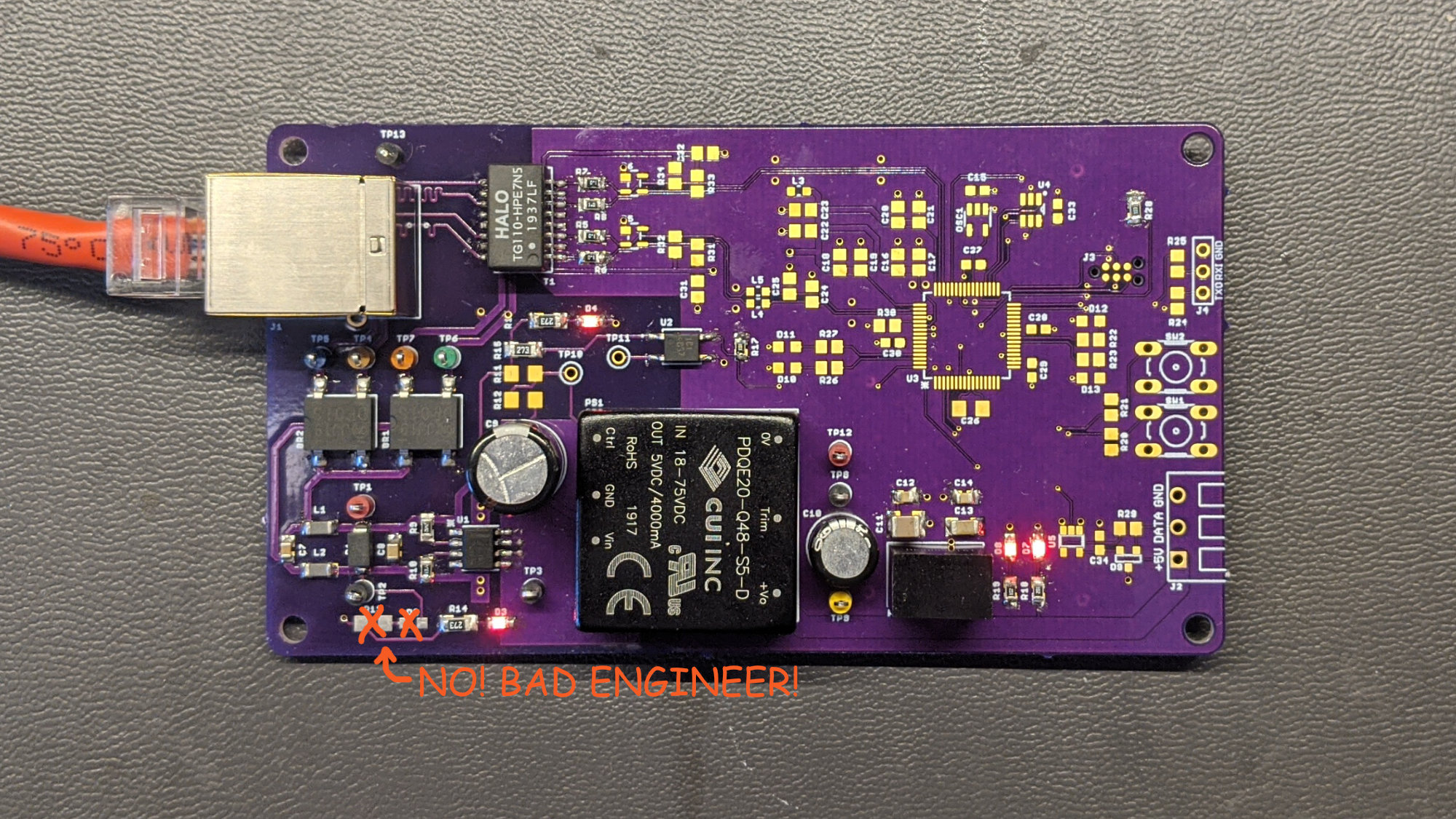
Bringing up the PoE+ PD circuitry and power supplies.
Once the boards arrived, I mounted the components required for PoE+ classification and the power supplies to the board as shown in the photo above. Initially the PoE classification failed every time. The switch would try twice about every three seconds. Some LEDs on the board would light briefly but classification would fail and the power supplies would not be turned on.
Eventually I traced the problem to a resistor and an LED I put across the output of the bridge rectifiers to try to indicate when the switch was supplying power to the board. This does not work. The current consumed by the LED in parallel with the detection and classification currents is not within the specs required for the detection and classification currents.
I removed the resistor and LED then detection and classification completed successfully. The 802.3at / PoE+ T2P LED lit then the 5 VDC and 3.3 VDC power supply LEDs lit. I used a multimeter to measure the 5 VDC and 3.3 VDC outputs. They were in spec so I proceeded to mount the microcontroller and the rest of the components.

My switch indicating the board is receiving power and has a valid IP address. This was before I was using the EUI-48 serial EEPROM to configure a MAC address.
Once the rest of the components were mounted, I downloaded the software I developed using the Olimex PIC-WEB board to my board. Everything more or less worked perfectly! My network switch indicated the power advertised by the board, the power consumed by the board, and the IP address assigned to the board by the DHCP server.
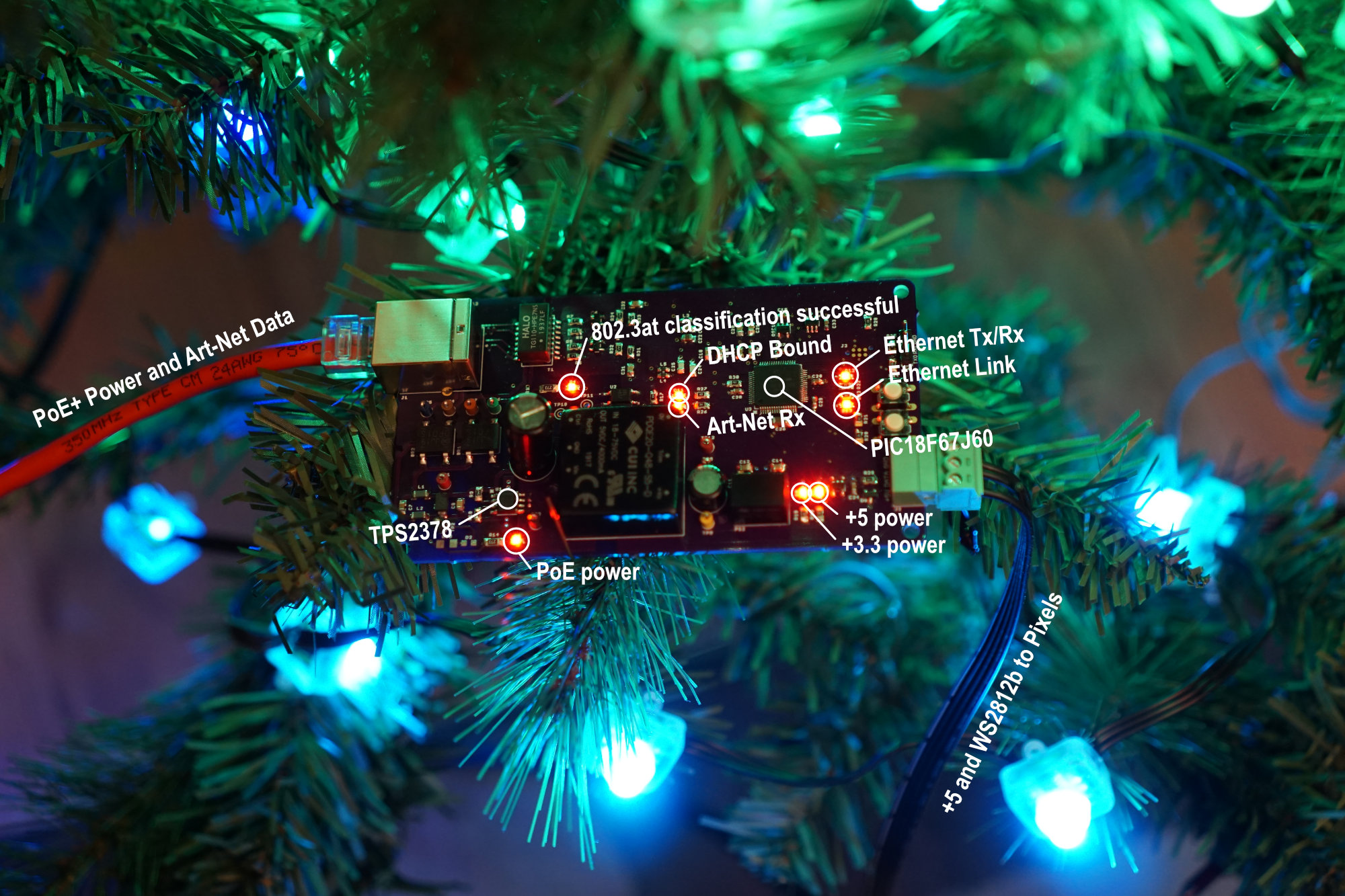
There were some small tweaks to the software that came later like adding code to get a real MAC address from the serial EEPROM and adding code to turn LEDs on and off to indicate the status of the DHCP client and when an Art-Net packet was received.
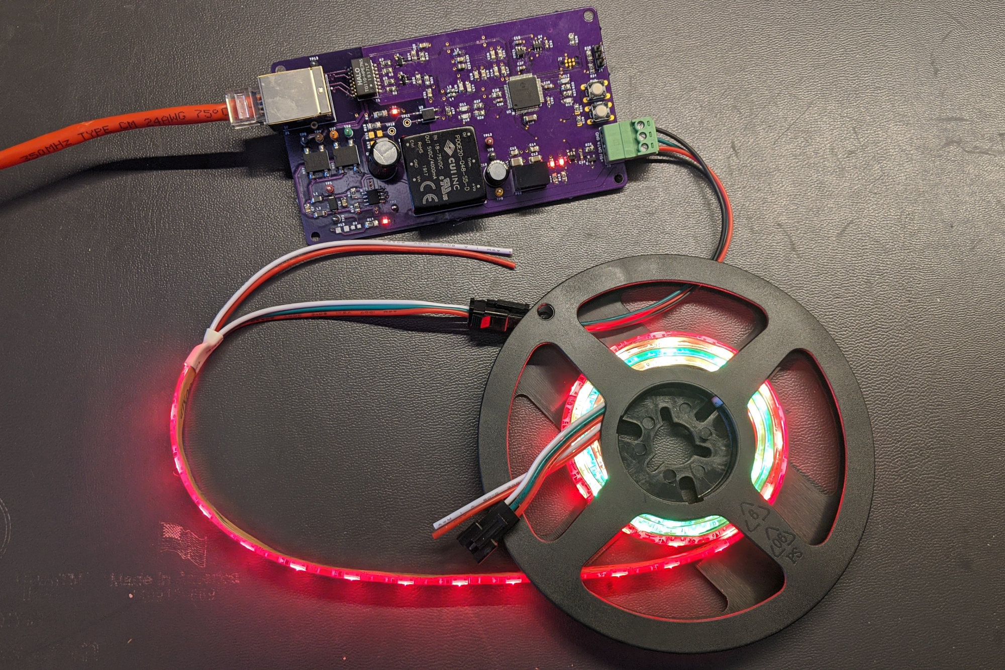
Completed board with a one meter strip of 60 WS2812 LEDs connected.
The photograph above shows the finished board driving a strip of 60 WS2812 LEDs. The power for the LEDs is delivered from an 802.3at / PoE+ capable network switch. The data for the LEDs comes from Art-Net packets generated by my PC.
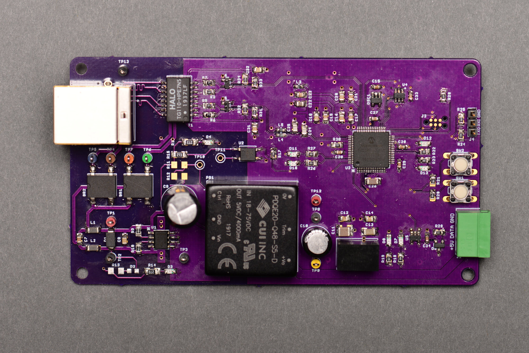
Photograph of the top of the completed board.
Above is a close up photo of the top of the finished board.
Photograph of the bottom of the completed board.
Above is a close up photo of the bottom of the finished board.
Decorating the Tree
A circuit board in a (fake) pine tree.
I initially used the one meter strip of sixty WS2812 pixels rather than the string of 50 pixels because the strip fit entirely on my desk and it was very easy to look and see if the pixels were displaying the patterns from my PC properly or not. Once the code was running properly, it was time to go bigger!
I grabbed the five meter string of 50 pixels and a cheap $20 fake tree from Michael’s and proceeded to string the lights on the tree. I stuffed the board in the tree then shot the quick video at the top of this post. I’m pretty sure the tree is not an ESD-safe location for the circuit board.

The decorated tree.
Above is a thumbnail from the video showing the decorated tree in my home office.
Future Power over Ethernet Projects
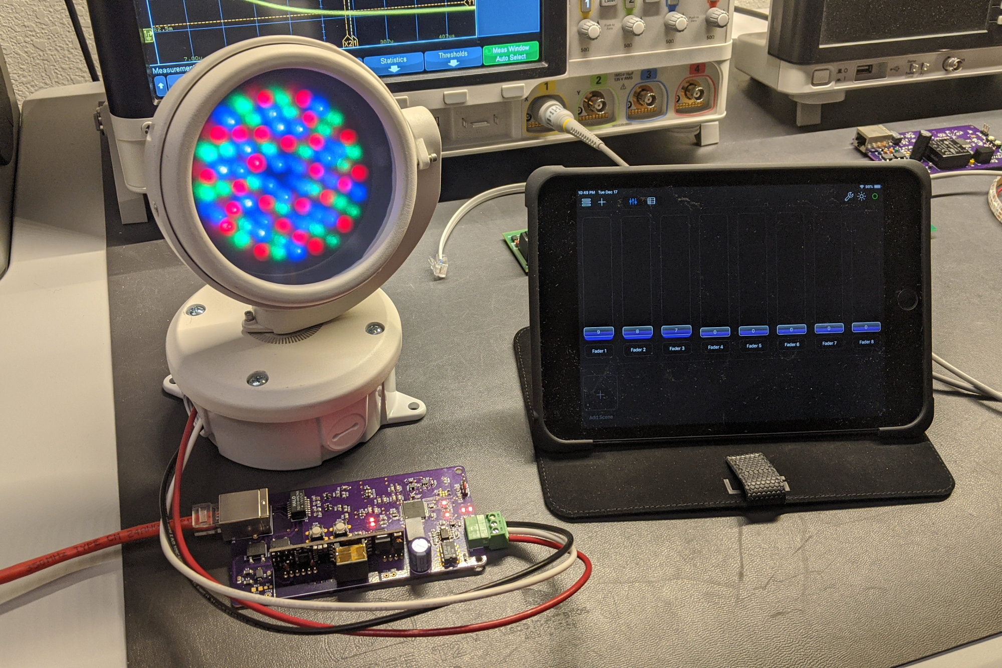
Philip Color Kinetics ColorBurst 4 10 watt RGB LED flood light controlled and powered over the network.
I have two more Power over Ethernet projects in progress. The first one is almost complete. It uses a Silvertel 24 volt isolated PoE+ module to power a Philips Color Kinetics ColorBurst 4 10-watt RGB LED flood light. Control data for the light comes from Synthe-Fx’s Luminair 3 software running on an iPad.
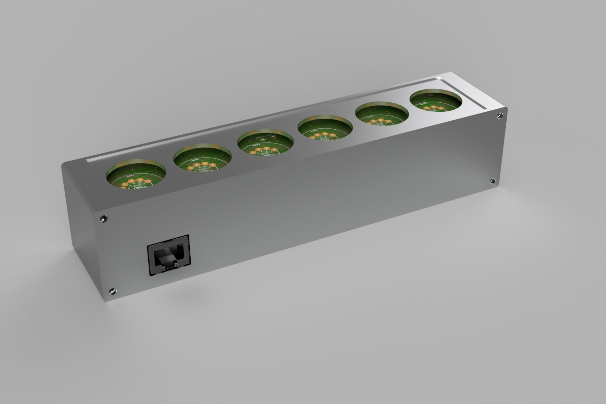
Rear view of the PoE-powered VFD tube clock enclosure.
The second project is an IV-12 VFD tube display that gets both power and time or other data for display over the network. This second project uses one of the Molex Ethernet jacks with integrated magnetics and 802.3at PoE+ classification circuitry. This project is in progress. I’ve ordered the aluminum panels for the enclosure shown above but am waiting on my VFD tubes to arrive before ordering the circuit boards for the project.
Design Files
Design files for this project are in the PixPoE repository in my github account. If anything’s missing or you have a question about something, you can find me on Twitter @bikerglen.