
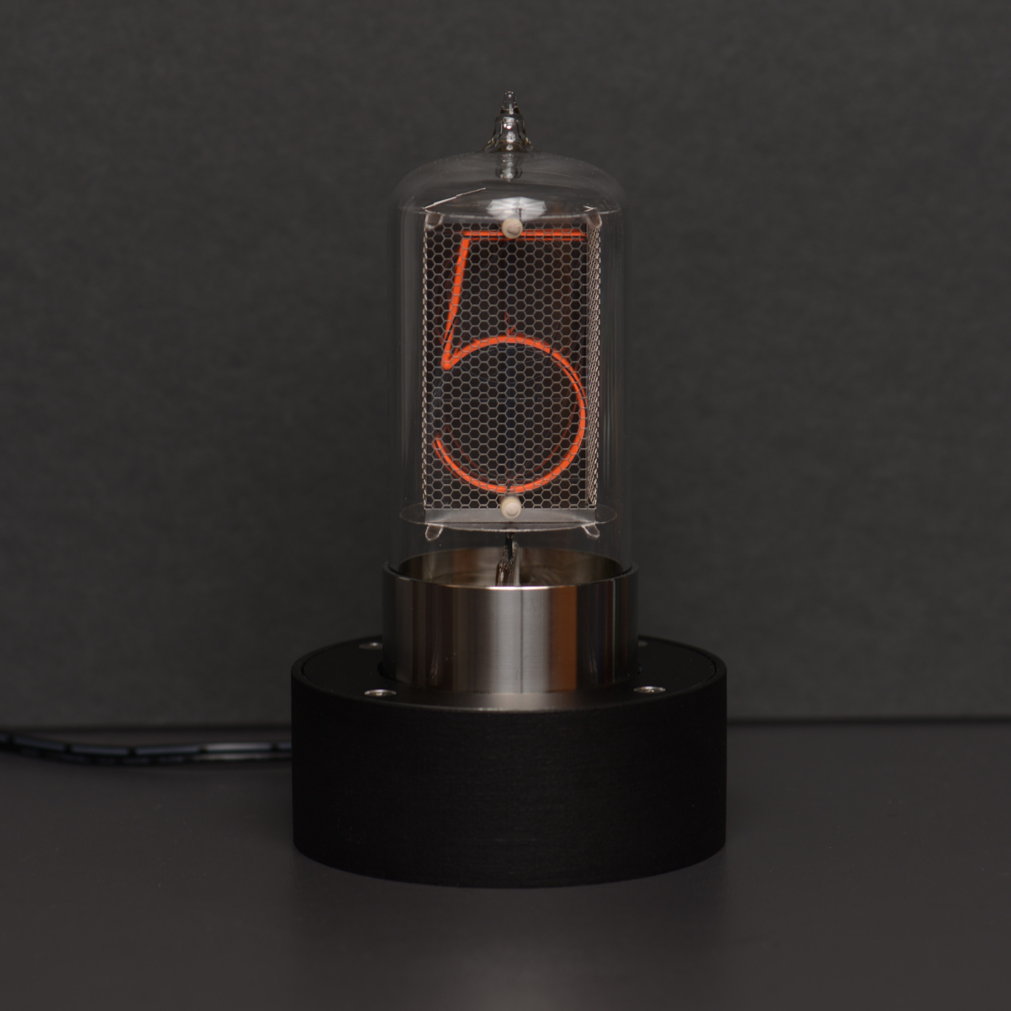
The finished project.
In the first post in this series, we designed a socket and driver board for a Dalibor Farny R|Z568M Nixie tube. In the the second post in this series, we designed a power supply and controller board for the Nixie tube. In the third and final post in this series, we’re going to design an enclosure to hold both boards and the Nixie tube.
Enclosure Design
The primary goals for the design of the enclosure were to match the aesthetic of the tube and to give the enclosure a very low profile so as not to distract from the warmth and beauty of the glowing tube. The first issue was sizing the enclosure to hold the circuit boards described in the previous posts.
The horizontal dimensions needed to accommodate a pair of 60.96 mm x 55.88 mm circuit boards. I decided on a cylindrical enclosure since the tube is cylindrical too. Using the Pythagorean theorem, the board diagonal was 82.689 mm. In addition, the enclosure walls would be 2 mm thick and I wanted a few millimeters of clearance. I settled on an outside diameter of 90 mm which would leave me with an interior diameter of 86 mm which was plenty of room.
The vertical dimensions were much more complicated. From top to bottom they needed to accommodate:
- A 2mm thick lid.
- A 5mm spacer. The lid and the spacer would cause the tube to sit recessed by 7 mm into the enclosure. This would ensure the base was fully seated below the top of the enclosure and protect curious fingers from the tube’s high voltage pins.
- The 1.6 mm thick socket and driver circuit board.
- An 11 mm spacer between the two boards.
- The 1.6 mm thick power supply and controller circuit board.
- The tallest component on the power supply and controller circuit board which was the 10.2 mm tall Cui switching regulator.
- The 2mm thick base of the enclosure.
This adds up to a minimum height of 33.4 mm for the enclosure. 90 mm x 33.4 mm isn’t exactly golden ratio type stuff but it’s still going to be capable of being a fairly low profile enclosure.
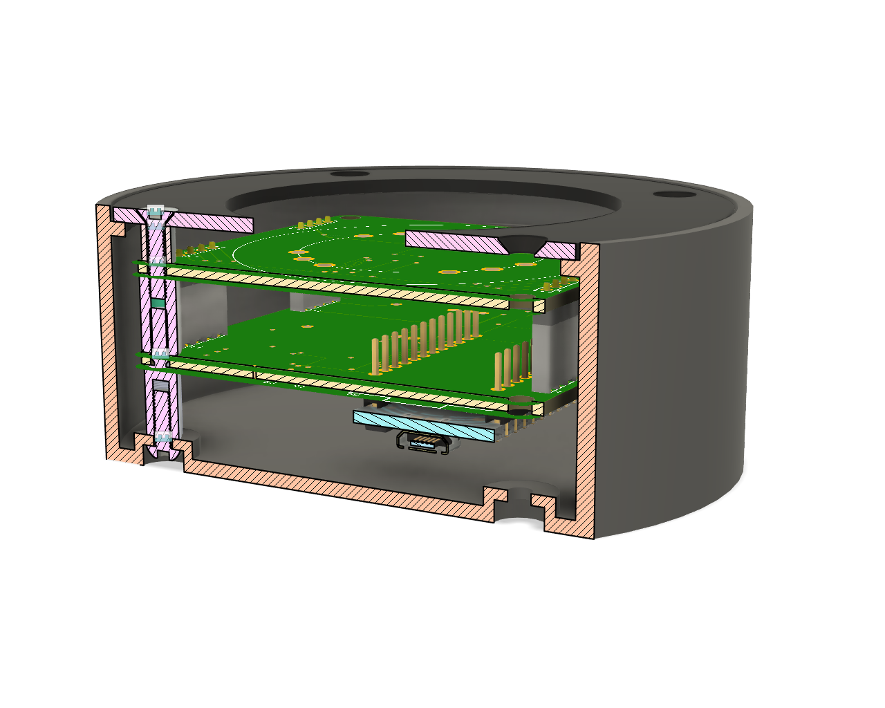
Cutaway view of the enclosure interior showing all the mechanical hardware and circuit boards.
I started sketching some ideas in Fusion 360 and ended up with the enclosure shown above. It ended up being 36 mm tall. This cutaway view shows the screws, spacers, standoffs, circuit boards, lid, and enclosure. The recesses for the bottom screw heads lift the 10 mm spacers by 2.5 mm thus leaving plenty of room for the 10.2 mm tall switching regulator to clear the floor of the enclosure.

Dimensioned drawing showing the vertical stackup of all the components inside the enclosure.
The dimensioned drawing above shows the dimension of each component contributing to the height of the enclosure. Units are in millimeters. There’s a slight gap not shown in the drawing bringing the total height to 36 mm.
The next component to design was a lid. The lid is 2 mm thick and sits on a 2 mm thick by 2 mm wide shelf around the circumference of the interior of the enclosure. It has countersunk holes so that flat head screws will sit flush with the top of the lid. I decided to 3D print the enclosure and CNC the lid out of anodized aluminum.
Enclosure Manufacturing
The enclosure was 3D printed using HP’s Multi Jet Fusion process then dyed black. Below are a few photographs showing all the details. I already secured the power cable bushing to the enclosure before taking the photos so it’s in all the shots. Here’s the interior.
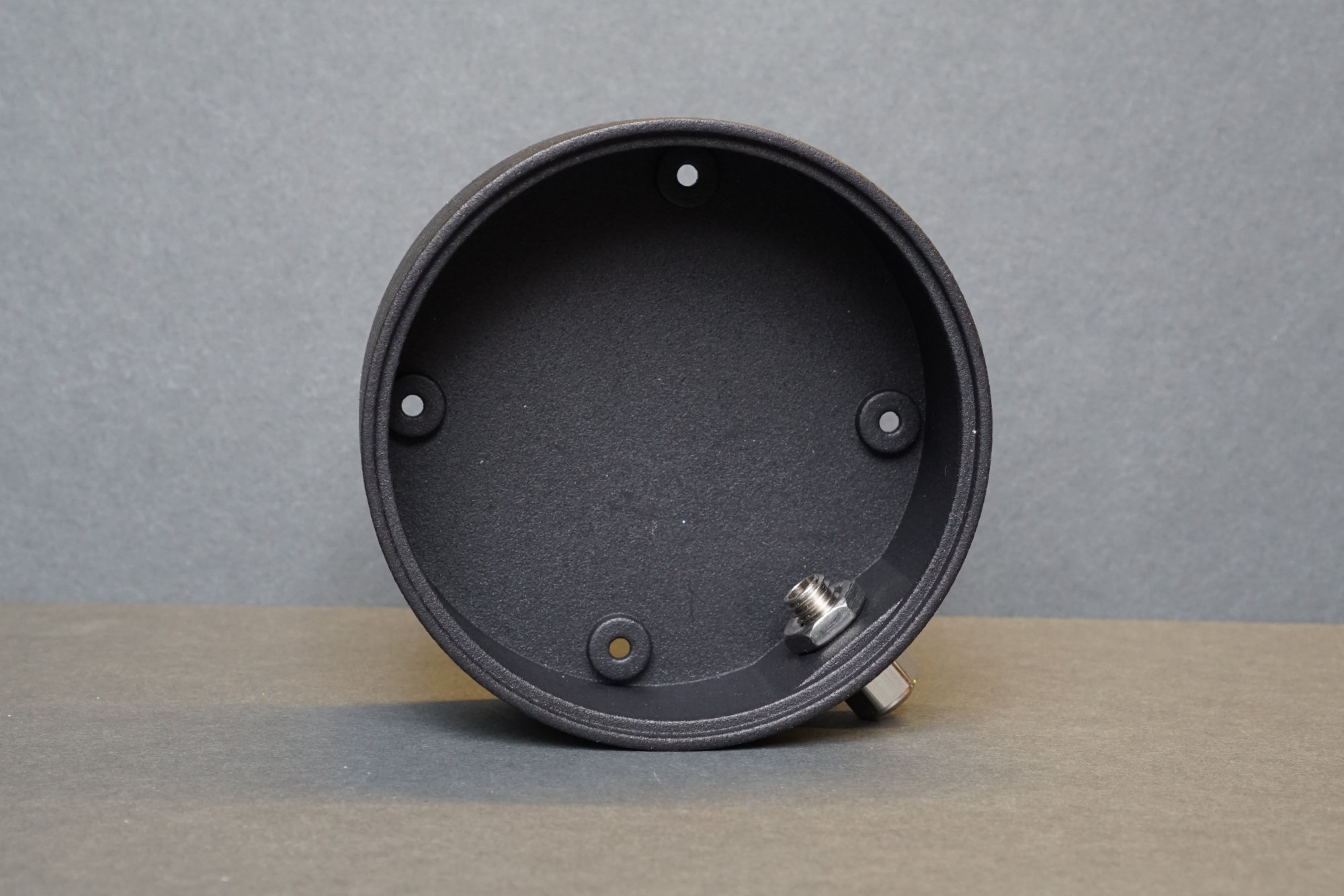
Inside view of enclosure.
Here’s the rear. I flattened a small section of the enclosure to hold the power cable bushing.

Rear view of enclosure.
Here’s the bottom. The recesses in the bottom allow the enclosure to sit flat after the screws are inserted.
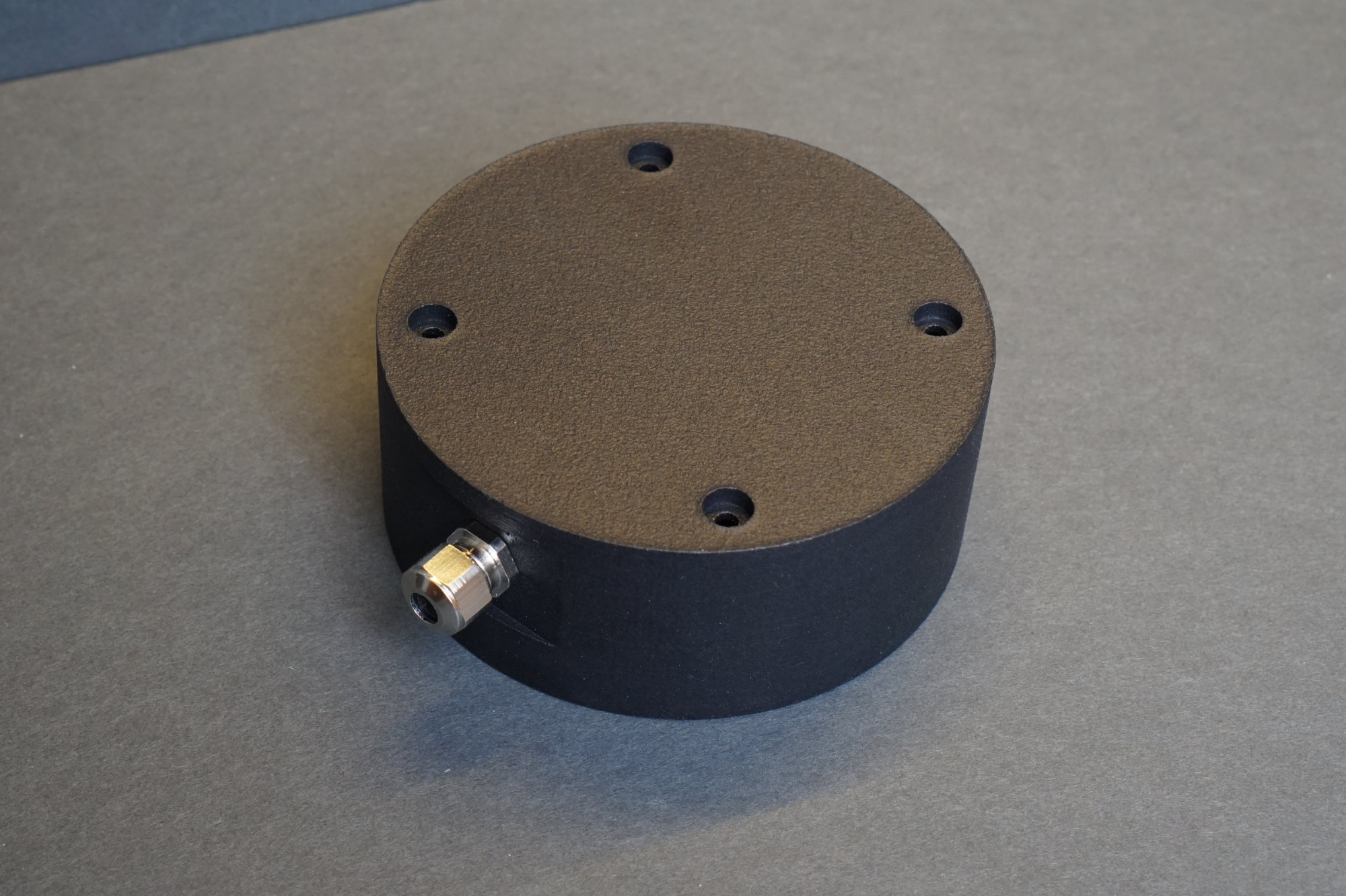
Bottom view of enclosure.
Lid Manufacturing

The CNC’d lid with countersunk screw holes.
I decided to have the lid CNC’d from a 2 mm thick sheet of black anodized aluminum. I’ve had success 3D printing flat objects like this lid but I like the look of the black anodization so I went with CNC machining instead of 3D printing. The aluminum is anodized before being cut so the edges and the screw recesses expose the raw aluminum underneath the anodized surface.
Screws, Spacers, and Stand Offs
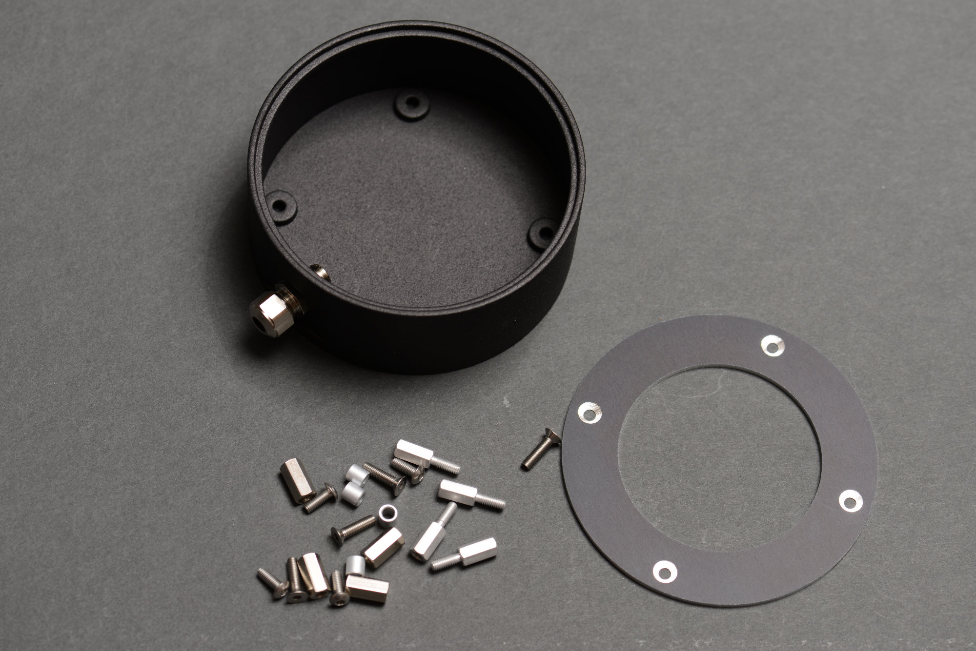
All the mechanical pieces.
Quite a bit of hardware is needed to assemble this project. The standoffs and spacers came from Digi-Key and the screws came from McMaster-Carr. The exact parts used were:
| Quantity | Supplier | Supplier Part # | Description |
|---|---|---|---|
| 1 | McMaster-Carr | 90710A120 | 18-8 Stainless Steel Thin Hex Nut, M8 x 1.25 mm Thread |
| 4 | McMaster-Carr | 92125A132 | 18-8 Stainless Steel Hex Drive Flat Head Screw, M3 x 0.5 mm Thread, 12 mm Long |
| 4 | McMaster-Carr | 92095A181 | Button Head Hex Drive Screw, Passivated 18-8 Stainless Steel, M3 x 0.50 mm Thread, 8mm Long |
| 4 | Digi-Key | R30-6200514 | ROUND SPACER M3 ALUMINUM 5MM |
| 4 | Digi-Key | 970110324 | BRASS SPACER STUD METRIC THREAD |
| 4 | Digi-Key | 24337 | HEX STANDOFF M3 ALUMINUM 10MM |
| 1 | Digi-Key | 1100.08.050 | CABLE GLAND 3.5-5MM M8 BRASS |
Assembly
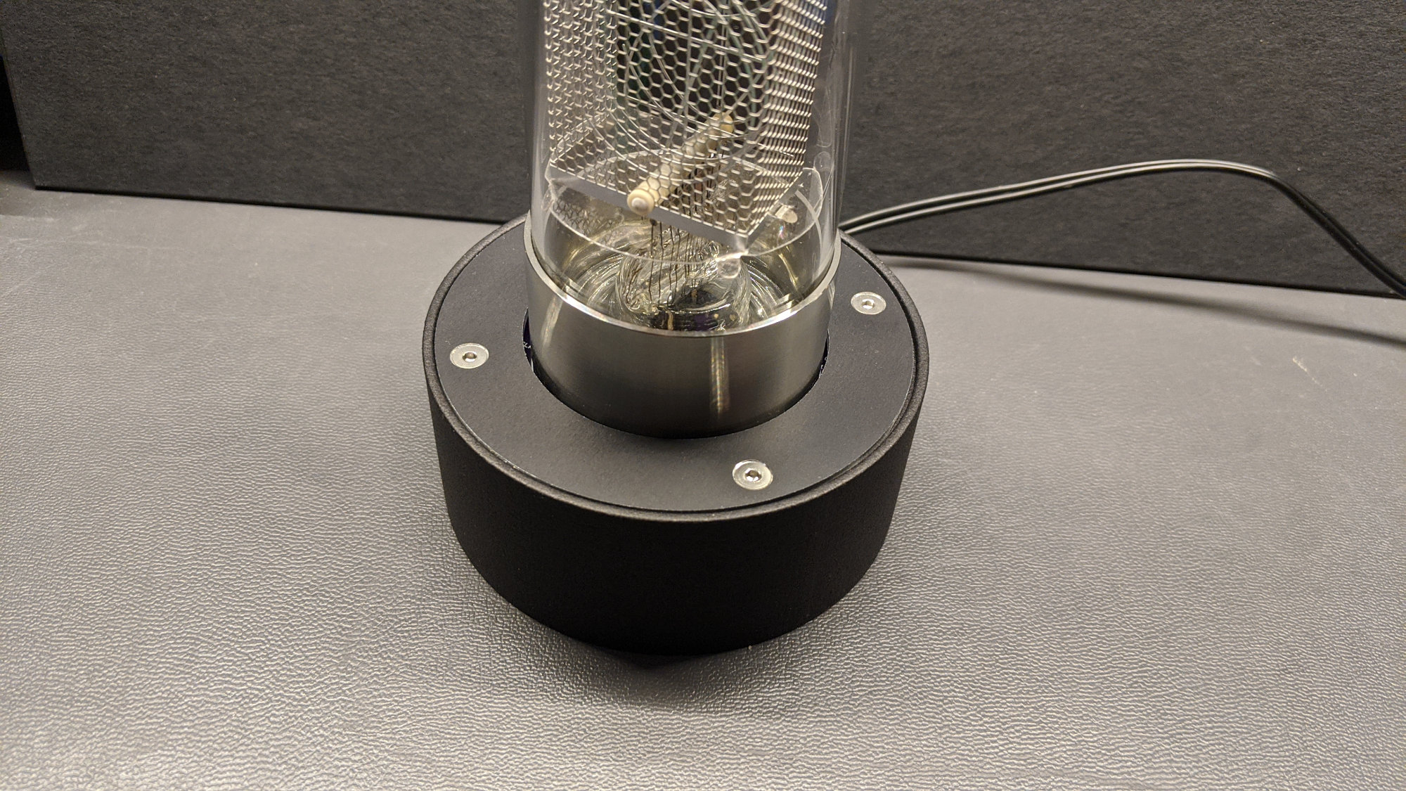
Here’s a close up of the enclosure to show how everything came together.
To assemble the enclosure, I started by threading the flat head screws through the aluminum lid, the 5 mm spacers, and the socket and driver board. The tube was already mounted to the socket and driver board. Once through I secured each screw with an 11 mm F-F threaded standoff. Next was to mount the power and controller to the bottom of the socket and driver board and secure the board using the 10 mm M-F threaded standoffs.
The next step was to mount the bushing to the enclosure, thread the power cord through the bushing, and connect the power cord to the power and controller board. Once that’s done lower the assembled unit into the enclosure while carefully pulling any slack in the power cord out the back of the bushing and enclosure. I routed the power cable down and underneath the board then back up to the bushing.
Once the power cord was through, I screwed the button head hex screws into the 10 mm M-F standoffs through the bottom of the enclosure.
Conclusion
The finished project.
That’s the finished enclosure for my Dalibor Farny R|Z568M Nixie tube. At this point I have a single digit display that counts through the digits zero to nine. In the future, I may modify the software to get the time from Particle’s servers or the temperature from the National Weather Service’s servers and display that on the tube. Hopefully, this post has been helpful if you’re looking to build your own Nixie tube controller or enclosure.