
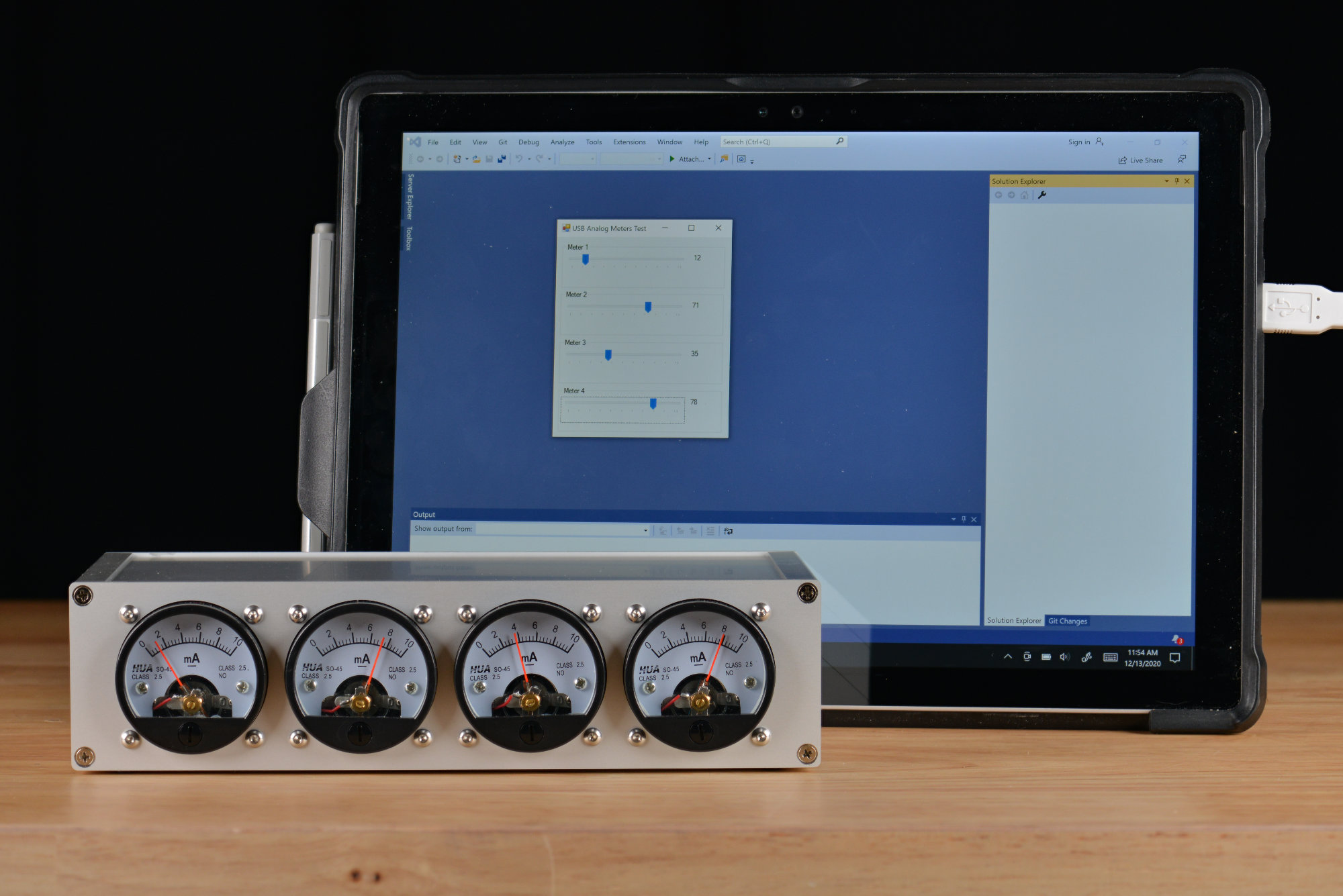
The USB analog panel meters controlled by a Windows 10 C# .NET app developed in Visual Studio 2019.
In the first part of this project, I acquired four round HUA SO-45 10 mA analog panel meters and built a board to control them over USB as a vendor-defined USB HID device. The next steps in this project are to build an enclosure for the meters and to develop a C# .NET graphical user interface to control them. Let’s take a look at designing the enclosure then we’ll take a look at building a simple Windows GUI to control them.
Building an Enclosure for the Meters
Connector Selection
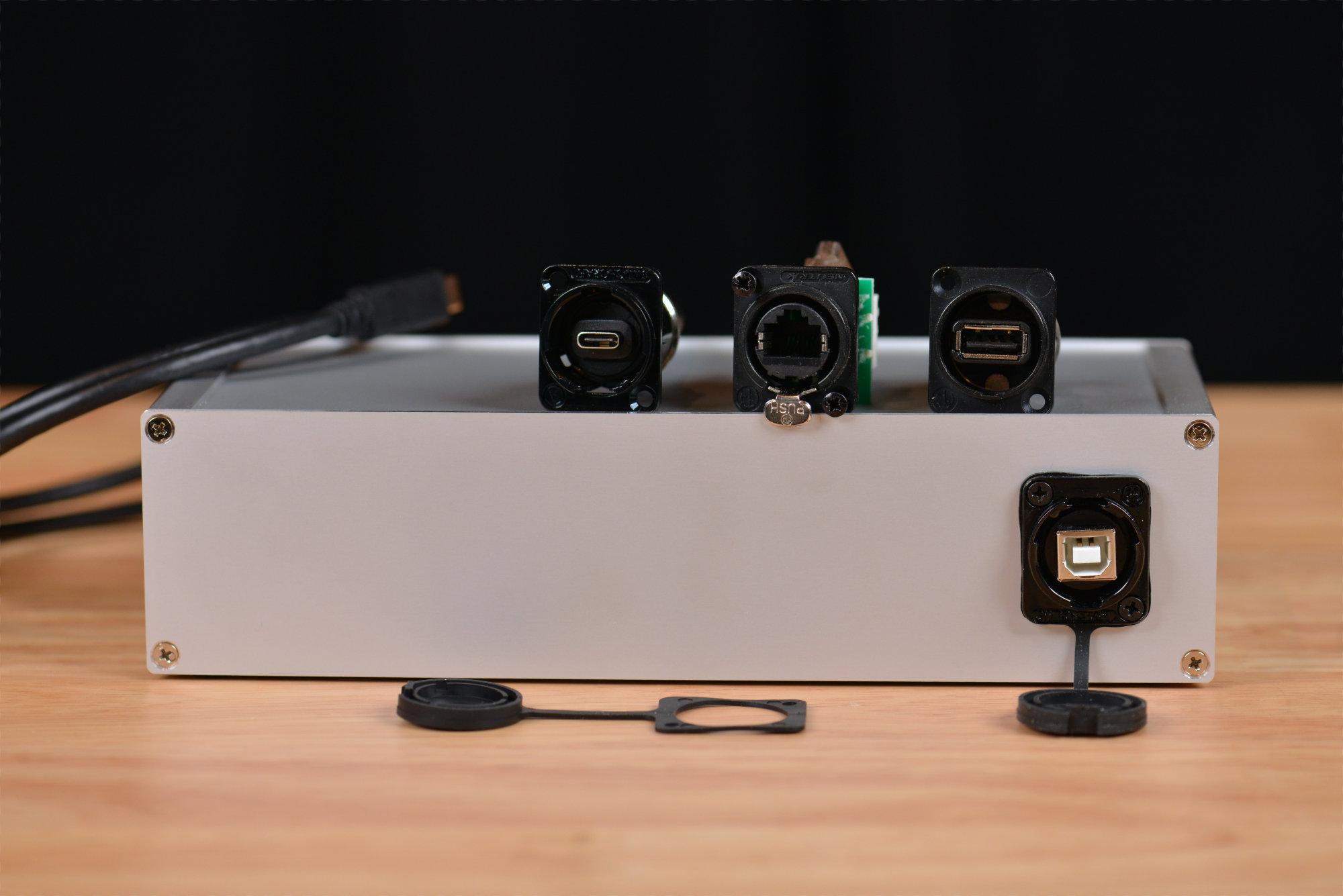
USB C, Ethernet, USB A, and USB B connectors in the XLR form factor from Neutrik and Switchcraft.
The first step in building the enclosure was to select a connector for the rear panel. I wanted a panel-mount USB Type B or USB Type C connector with a strong preference for the latter. I also wanted the connector to share the same cutout with an RJ-45 connector in case I wanted to convert this to an Ethernet/PoE project in the future. Even though I’d need a new controller board for the meters, this would save the expense of cutting a new rear panel for the enclosure.
I did some searching for circular panel mount USB and Ethernet connectors. These all tended to be mil-spec with a corresponding mil-spec price tag, and, furthermore, the USB and Ethernet versions used different sized cutouts.
Fortunately, both Neutrik and Switchcraft make a wide variety of connectors that all fit into the standard cutout used by XLR audio connectors. These were more affordable than the circular connectors and the USB and Ethernet versions could be swapped without the need for a new rear panel.
The photo above shows a USB 3.0 Type C connector from Switchcraft, an RJ-45 8P8C Ethernet and USB 2.0 Type A connector from Neutrik, and a USB 2.0 Type B connector from Switchcraft. Both manufacturers make these for just about all popular data and multimedia connectors. Between the two companies, the only missing common connector type is a 5.1 mm x 2.1 mm DC jack.
The Switchcraft USB 3.0 Type C connector comes with a permanently attached three foot pigtail ending with a USB 3.0 Type C plug. This could plug directly into the USB Type C connector on the control board. Unfortunately, there was just no way to spool up that much excess wire inside my enclosure so I went with the USB 2.0 Type B connector.
Enclosure Design
The CNC enclosure was cut at Front Panel Express. I used their free design software to cut the design the panels then uploaded the design files to their website for manufacturing.
Enclosure Wizard
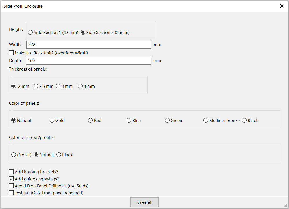
The parameters used to create the basic enclosure.
On the toolbar is a button that brings up a wizard for specifying the dimensions and options for the enclosure. I specified the needed size for my enclosure then clicked “Create!”. The enclosure wizard then generated the blank panels for the top, bottom, front, and rear of my enclosure. It also added a screw kit and the extruded aluminum side profiles for the enclosure to their shopping cart software.
Front
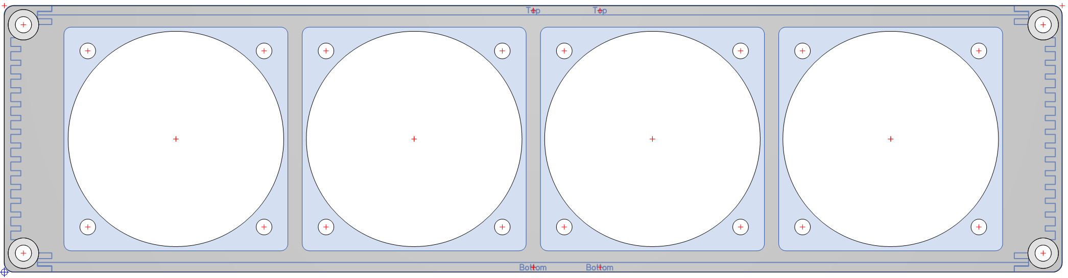
The front of the enclosure design.
The front of the enclosure has cutouts for four of the meters and their mounting screws. The meters are spaced 50 mm on center.
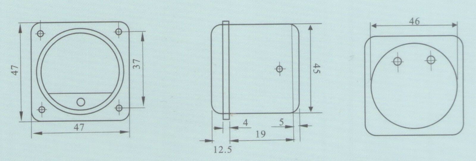
Meter dimensions from the eBay store where I purchased the meters.
The meter dimensions were taken from an image on the eBay store where I purchased the meters. The meter is specified as 45 mm in diameter. I made the central hole for the meter 45.25 mm. This seemed to work well. For the mounting holes for the meters, I used 3.3 mm diameter holes. This diameter will give a loose fit for the M3 screws used to secure the meters to the front panel.
Rear
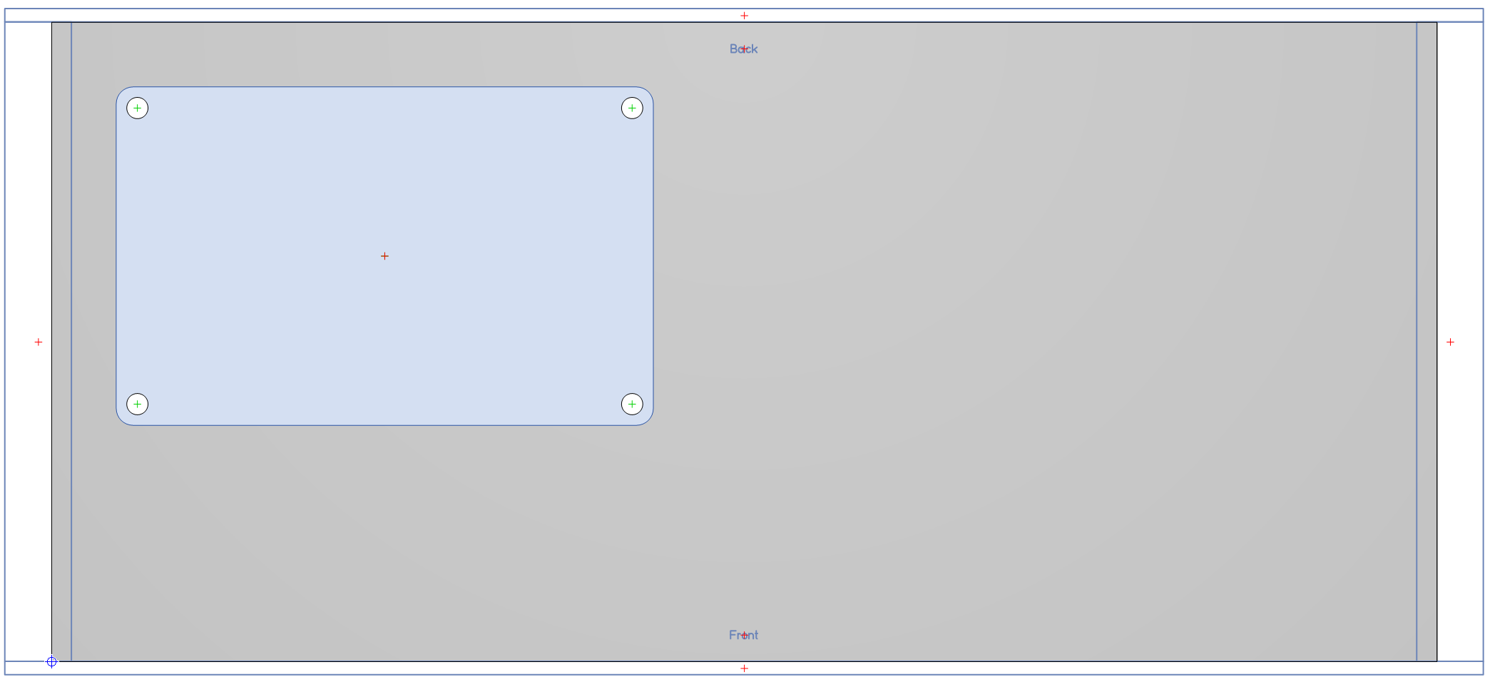
The rear of the enclosure design.
The rear was much simpler. I grabbed the recommended cutout dimensions from the manufacturer’s data sheet and created the corresponding cutout on the rear panel.
Top

The top of the enclosure design.
For the top panel, I reduced the panel thickness from 2.0 mm to 1.5 mm. With the thinner panel, the machining on the left and right edges was no longer needed to make the panel fit in the slots for it on the side profile extrusions.
Bottom
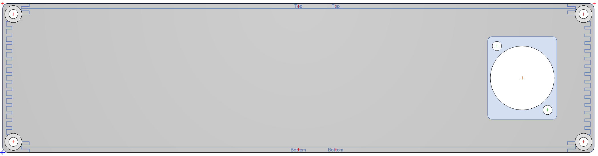
The bottom of the enclosure design.
For the bottom panel, I reduced the panel thickness from 2.0 mm to 1.5 mm to avoid the edge machining too. I transferred the dimensions of the circuit board from Eagle to the panel design software then placed four holes to hold the circuit board. The view in the software is of the bottom of the enclosure so everything is mirrored about the vertical axis.
Pricing
The total cost for the enclosure was $145.89. The cost was the primary reason I wanted to be able to reuse the enclosure should I convert this to an Ethernet project in the future.
Finished Enclosure
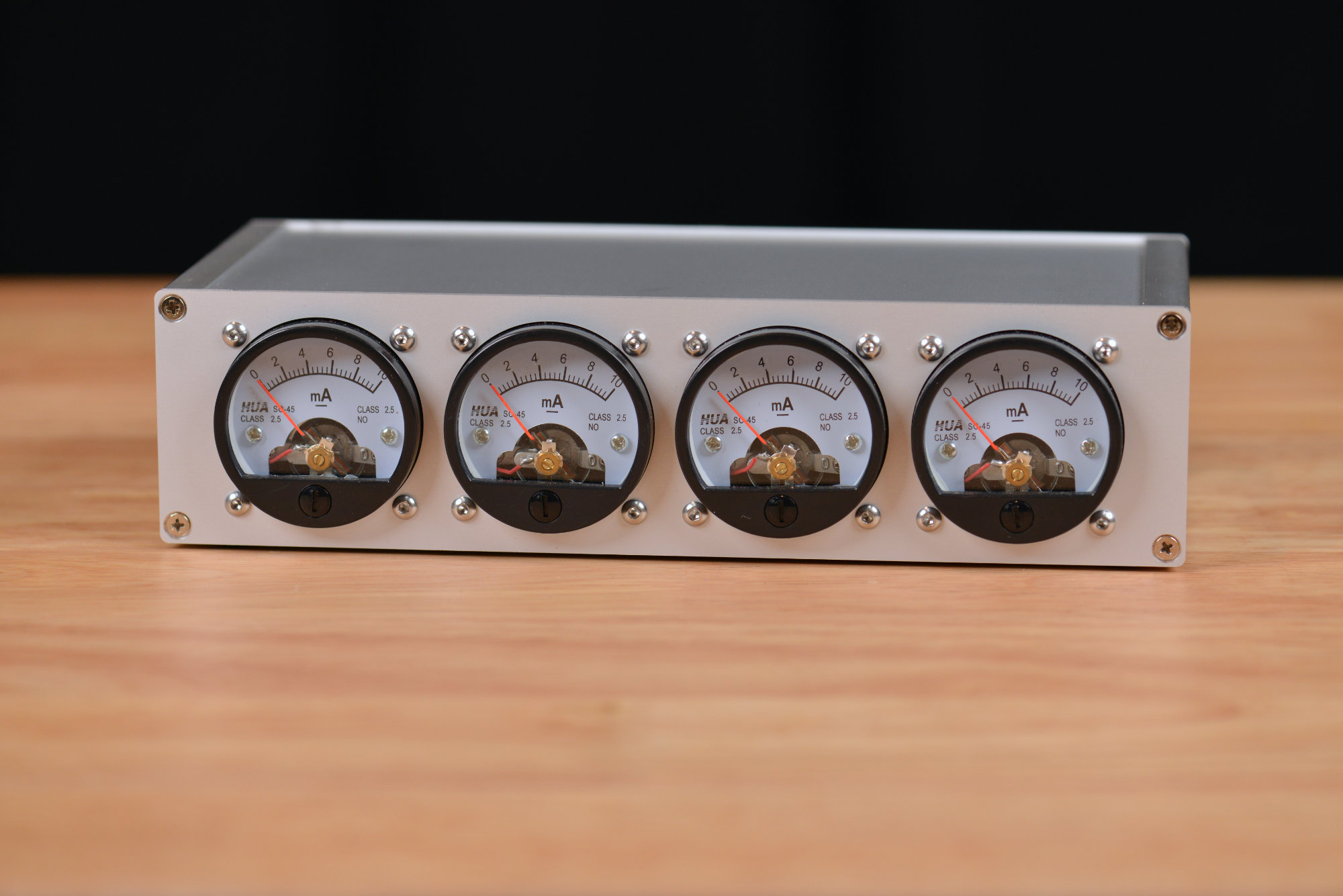
The front of the completed enclosure.
The finished panels arrived and I installed the meters then assembled the enclosure. The front of the enclosure is shown in the photo above.

The rear of the completed enclosure.
The rear of the enclosure is shown in the photo above.
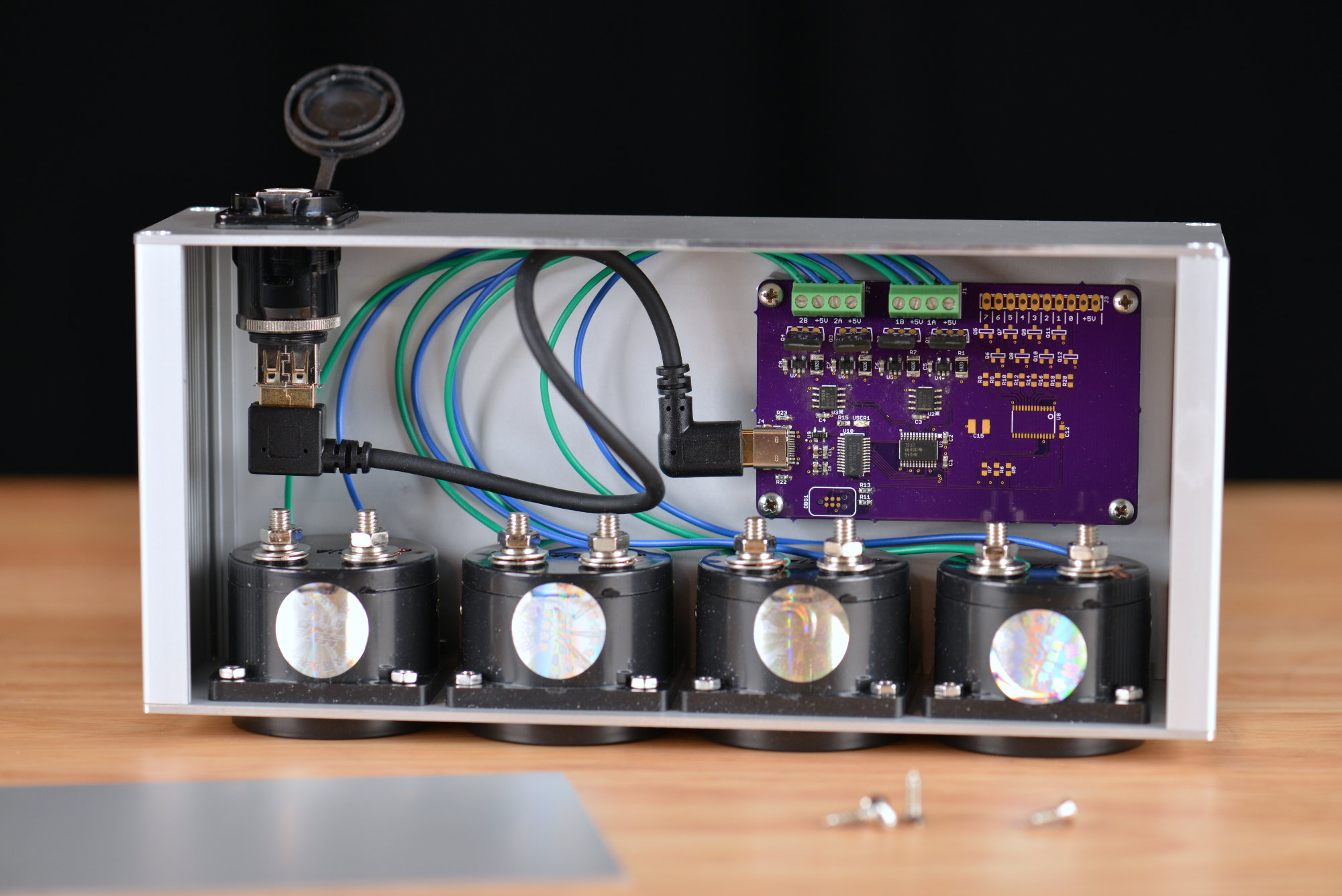
The interior of the completed enclosure showing how everything fit together.
The inside of the enclosure is shown in the photo above. I used a short USB A to USB C right angle cable to connect the rear panel connector to the circuit board. There’s probably room for the three feet of cable on the USB C version of the rear panel connector but this seems to be the cleaner solution in my opinion.
Building a Windows 10 C# .NET App to Control the Meters
After finishing the enclosure, I decided to try controlling them under Windows 10. I have some C# .NET experience so I started searching for a C# .NET USB HID library. I eventually found Mike O’Brien’s HidLibrary on Github and quickly dug into the examples.
The examples in the examples directory were all C# console apps and did not demonstrate how to control USB devices across multiple threads. The TestHarness inside the src/TestHarness directory though was a .NET forms app and did demonstrate how to use the HidLibrary across multiple threads.
Designing the GUI
The details of designing your first C# .NET forms app is beyond the scope of this blog post. However, Microsoft has a great series of tutorials on their website. I recommend starting with the Picture Viewer tutorial then working through the rest of the tutorials as needed. We’ll be designing a Windows C# .NET forms app just like in the first tutorial.
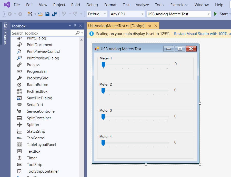
The simple GUI for controlling the meters.
For the user interface, I decided I wanted a trackbar and a label for each of the four meters on the hardware. Dragging the slider on the trackbar would change the value on the label and the level on its meter on the hardware.
I created a new Windows C# .NET forms project then used the forms designer to design a simple form with four trackbars and four labels as shown in the above screen capture. You can run the project at this point, move the sliders around, and see what the application will look like but otherwise it doesn’t do much–yet. We’ll connect the trackbars’ ValueChanged events to code later.
Adding the USB HidLibrary DLL to the Project
The next steps are to build the HidLibrary DLL then add a reference to the DLL to the project.
Build the HidLibrary DLL
The necessary USB HidLibrary DLL is not included in the HidLibrary source download from Github. To build the DLL, navigate to HidLibrary-master\src and open the HidLibrary.sln in Visual Studio. You’ll get a few warnings about only opening solutions and projects from trusted sources.
Once the solution is open, find the HidLibrary project in the HidLibrary solution using the solution explorer pane. Right click on the HidLibrary project then select Build. Once the build is compete, the HidLibrary solution and project can be closed.
Add a Reference to the HidLibrary DLL to Our Project
Now back to our project. On the Solution Explorer, find the analog panel meters project then the “References” section. Right click on this then select “Add Reference.” In the dialog that appears, click “Browse” in the left pane then click “Browse…” in the lower right hand corner.
Use the file browser dialog to navigate to the location of the downloaded copy of the HidLibrary then find HidLibrary-master\src\HidLibrary\bin\Debug\netstandard2\HidLibrary.dll that you just built. Once selected, click OK to add the library to the references.
Finding the Meters
Before we can interact with the meters, we need to find the meters! Following the TestHarness example included in the HidLibrary source code, we’ll attach some code to the Form.Load event handler to search the USB bus for our meters and open a connection to them. The Form.Load event occurs after all aspects of the form have been initialized but before the form is displayed.
To connect some code to the event, click on the main window in the forms designer. Be sure it’s the main window that is selected and not one of the trackbars or labels. In the properties pane, click the events lightning bolt and look for the “Load” event. Add the text “FormLoad” to this event then double click on it. This will create a new, empty block of code called FormLoad inside the class for the form.
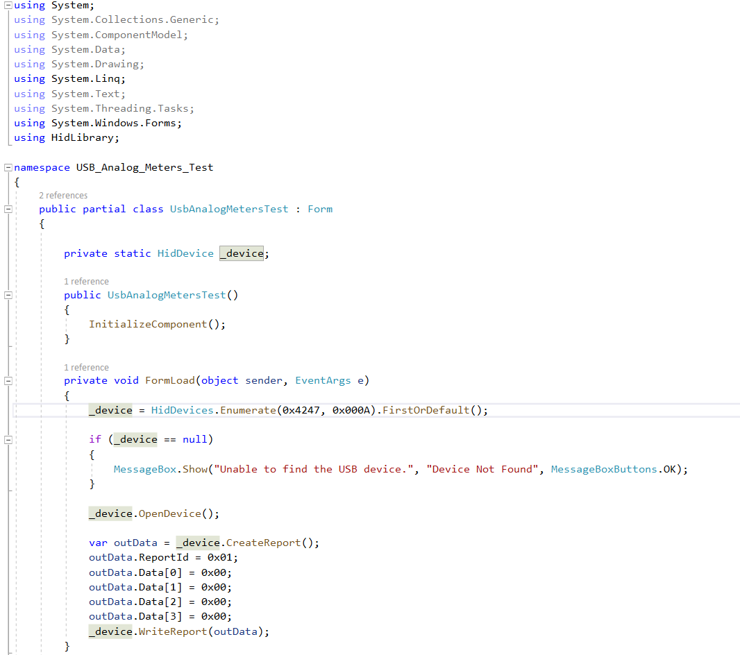
The first additions to the forms code to find and use the USB panel meters.
To use the HidLIbrary and open the USB analog panel meters, we need to make three modifications to the code. These modifications are shown in the image above.
- Add “using HidLibrary;” under the rest of the using statements.
- Declare the private static variable _device of type HidDevice inside the class for the form.
- Add the code shown above to the FormLoad function.
The using statement tells Visual Studio that we’ll be referring to the HidLibrary inside this file. The HidDevice variable is used to reference the USB device we’ve found in other places in the code. The FormLoad code looks for the first USB device with the matching vendor ID and product ID and attempts to open that device. If the device is not found, a dialog is displayed to that effect. If the device is found, it is opened and a USB OUT report is sent to the device to set all the meters to zero.
Controlling the Meters
In this step, we’ll attach code to the ValueChanged event for each of the four trackbars. The code will update the value on the label next to the trackbar then send a USB OUT report to change the value displayed on the meter.
Go back to the forms designer and click on the top most trackbar to select it. Click on the events lightning bolt in the property pane and find the ValueChanged event. Double click on the text field and a function with a default name will be attached to the event and the editor will open with a blank empty function of the same name inside the class for the form. Add the code shown below to the function.
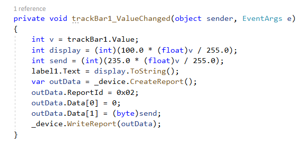
The code for one of the trackbar’s ValueChanged event.
This code does the following:
- It gets the value of the trackbar. This value is from 0 to 255.
- It converts the value from 0 to 255 to a percentage from 0 to 100.
- It converts the value from 0 to 255 to a calibrated from 0 to 235 that will cause the meter to register from 0 to 10 mA.
- It updates the label to the right of the trackbar with the percentage.
- It sends the calibrated value from 0 to 235 to the USB analog panel meters using a USB OUT report.
After creating the ValueChanged event handler for the first trackbar. Repeat this for the remaining trackbars.
This project only sends USB OUT reports to the meters. Other projects may need to listen to USB IN reports from their hardware. This is slightly more complicated because the thread listening for USB IN reports will not be the same thread that is running the forms user interface. This requires using C#’s invoke mechanism to call code and pass data across threads. If your application needs to do this, the TestHarness example provided in the HidLibrary source code contains the relevant code.
Design Files
The enclosure design files and Visual Studio solution for this project can be found in the Github repository for the USB Analog Panel Meters project.
Postface
If I had to do this project again, I probably would opt for a set of screw terminals rather than a USB Type C connector on the main board. This would allow me to use a cable cut to size rather than having to rely on the selection of short cables I could find on Amazon or eBay. It would also eliminate an extra connector inside the enclosure.