
I first saw a Scramblepad on the door of an office building I worked at while in high school in the late ’80s. I always wanted to own one or to make my own based on seven-segment LED displays but had trouble finding a suitable, transparent touchpad I could use for the buttons. I eventually gave up on building my own.
Luckily I found a few Scramblepads up for sale recently and decided to buy one to see if I could do anything useful with it. With a bit of work, I reverse engineered the communication protocol and can now use my Scramblepad with my own simplified homebrew door controller. Read on to learn more about the hardware, the communications protocol, and building a homebrew Scramblepad compatible door controller.
Why a Scramblepad / Why not a Scramblepad
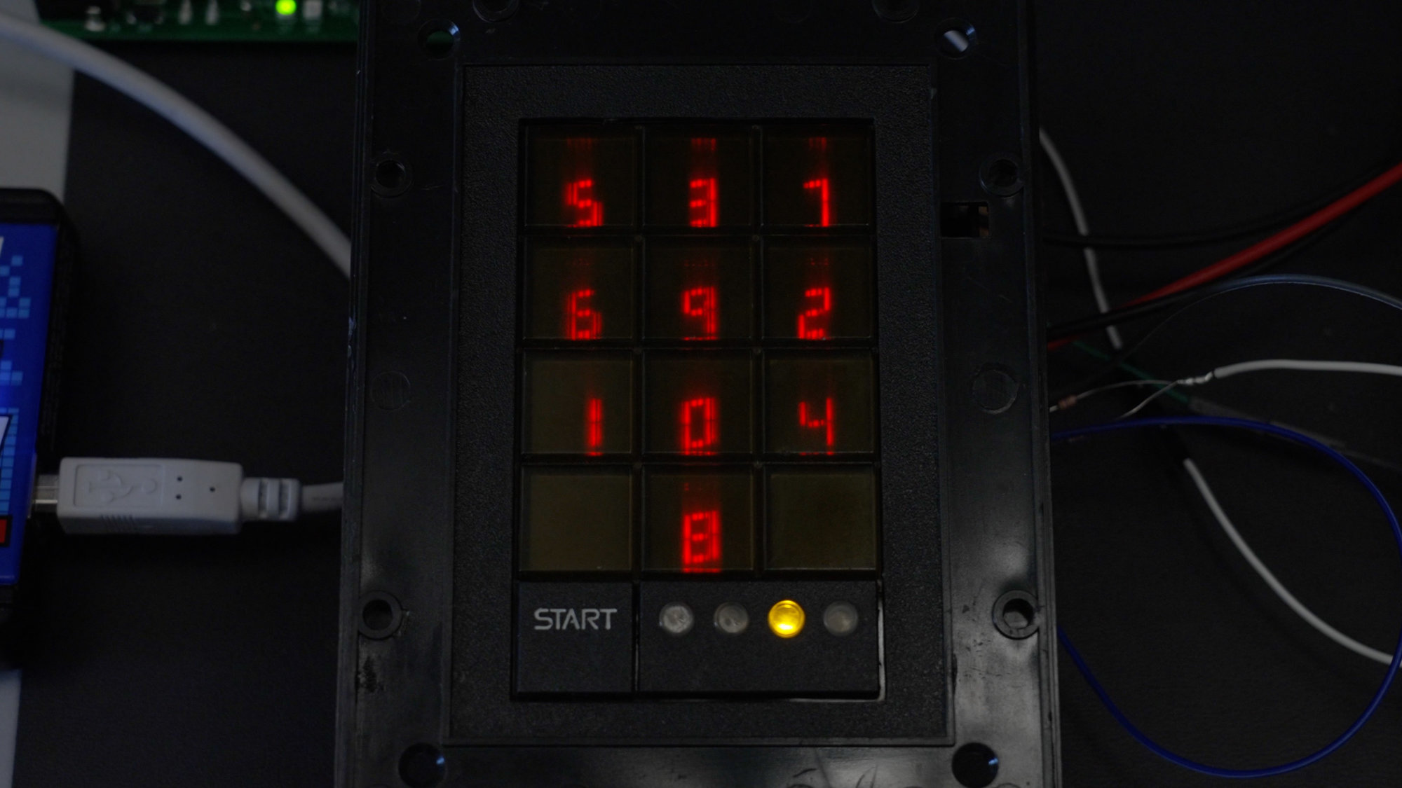
The front face of the Scramblepad with randomized digits shown on the RED LED seven-segment displays.
The original Scramblepad patent was filed in 1982. An office building I worked at while in high school had one on the door for after hours / weekend access. Even though they’re very old by technology standards, they’re still somewhat fascinating today. I’ve heard anecdotal reports that a few office buildings in downtown Denver still have them.
The primary purpose of a Scramblepad is to prevent shoulder surfing the PIN needed to gain entry to a building. The Scramblepad has two strategies to prevent shoulder surfing:
- The location of the LED digits on the keypad are scrambled on every activation. This prevents a person standing at a distance from watching where a user’s fingers land on the keypad and learning the code.
- The viewing angles of the LED digits are heavily restricted. A user has to be directly on-axis horizontally to see the digits. The viewing angle is restricted vertically as well but not quite as severely. This prevents shoulder surfing by a person standing behind the Scramblepad’s user from learning the code.
The use of Scramblepads has fallen out of favor for a variety of reasons. They’re not ADA compliant. They need to be mounted at a specific height to let most users view the randomized digits through the viewing angle restrictions. This prevents users in wheelchairs from seeing the digits and using the keypad unless a second lower Scramblepad is installed alongside the higher Scramblepad. They’re also completely inaccessible to vision-impaired and blind users.
Even with proximity card readers, Scramblepads no longer provide adequate security. The protocol between the reader and the door controller is archaic and unencrypted. They’re also not vandal proof. Finally, they’re expensive. In the case where just a PIN is needed to enter a building, lab, or supply closet, it’s much less expensive to put a mechanical code lock on the door and call it done.
A Closer Look at the Scramblepad Hardware
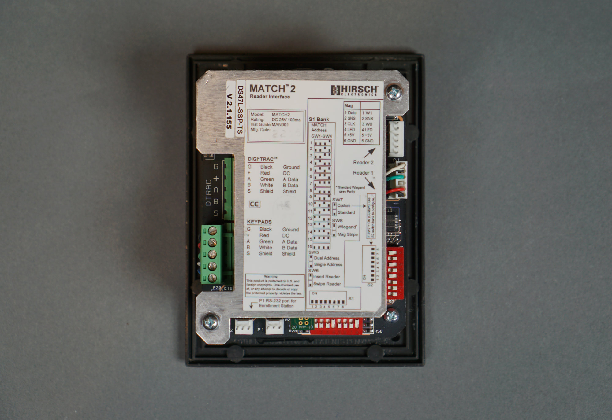
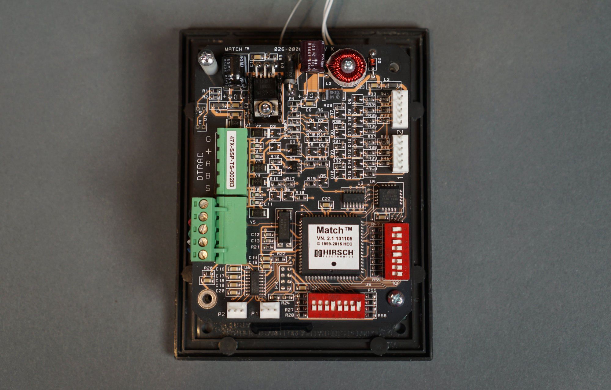
Rear view of the Scramblepad showing the connectors and dip switches.
Let’s take a closer look at the Scramblepad hardware. On the back of the Scramblepad are a bunch of connectors and dip switches. The door controller connects to the DTRAC connector mid way down on the left. The other connectors connect the various boards inside the Scrambledpad together and allow for a door exit card reader to be connected to the Scramblepad for card + pin to enter then card-only to exit situations.
At the bottom is an eight-position DIP switch. The primary purpose of this switch is to set the address of the Scramblepad. The address set on the switch must mach the port the Scramblepad is connected to on the door controller. I have not investigated the eight-position DIP on the right.
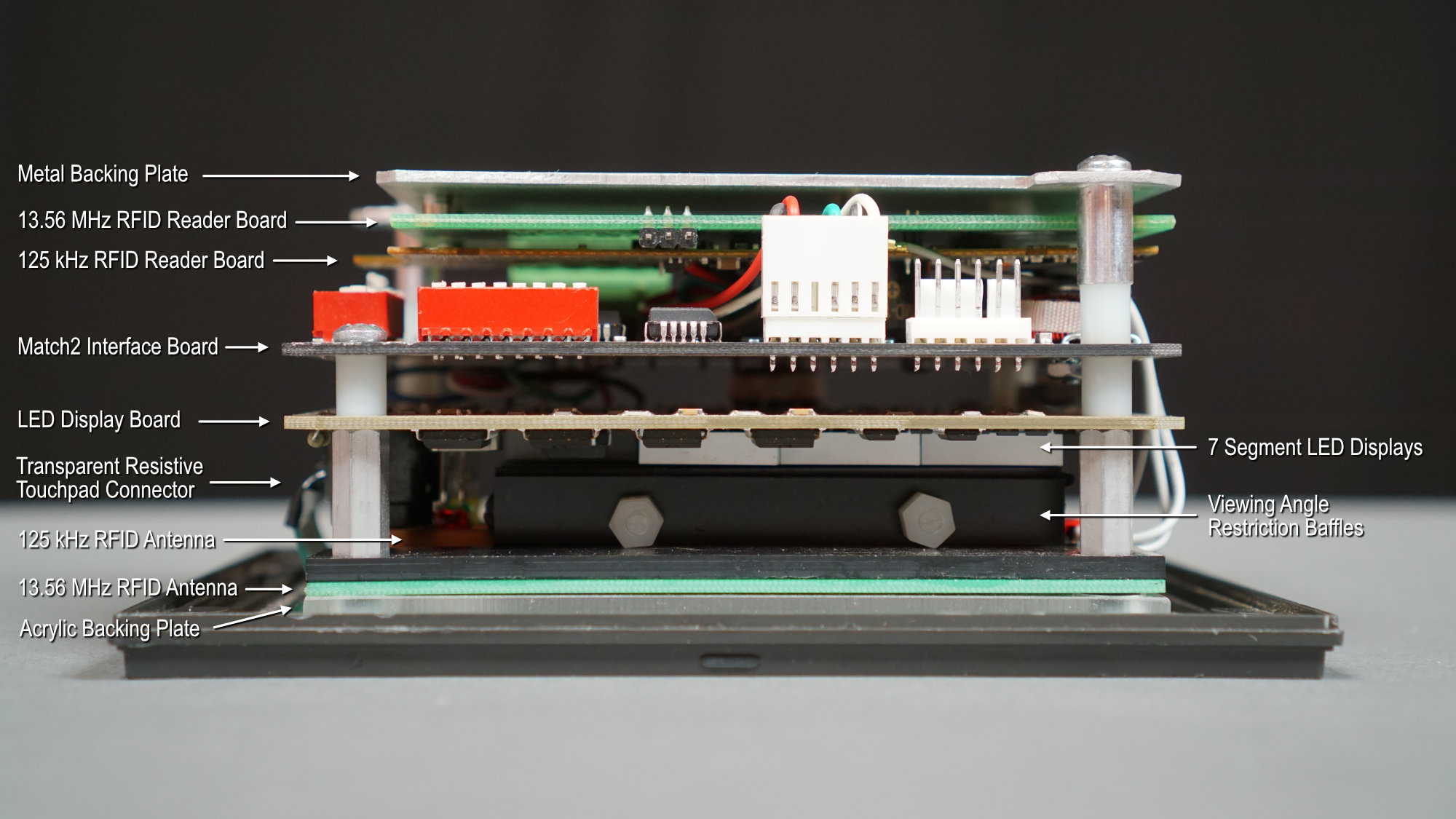
Annotated side view of a Scramblepad.
The Scramblepad is complicated. The photo above shows the layers of mechanical and electrical hardware inside the Scramblepad. From bottom to top, this hardware consists of:
- A plastic bezel with a snap-on plastic trim piece.
- A transparent rubber membrane forming the buttons.
- A transparent 3×4 touchpad button matrix.
- A transparent acrylic back plate for the button assmebly.
- A 13.56 MHz RFID PCB antenna.
- A 125 kHz RFID coil antenna.
- A series of metal baffles to restrict the digit viewing angles.
- Ten seven-segment LED displays.
- An LED display board.
- A Match2 interface board.
- A 125 kHz RFID reader board.
- A 13.56 MHz RFID reader board.
- A metal back plate.
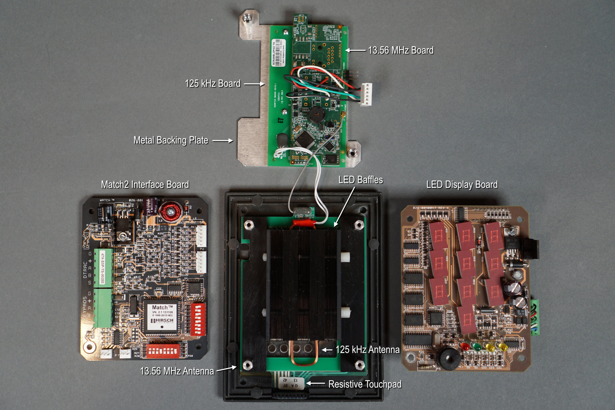
Exploded view of the Scramblepad.
The Scramblepad comes apart easily by removing four screws. The photo above shows the Scramblepad after removing these four screws and separating the boards from each other.
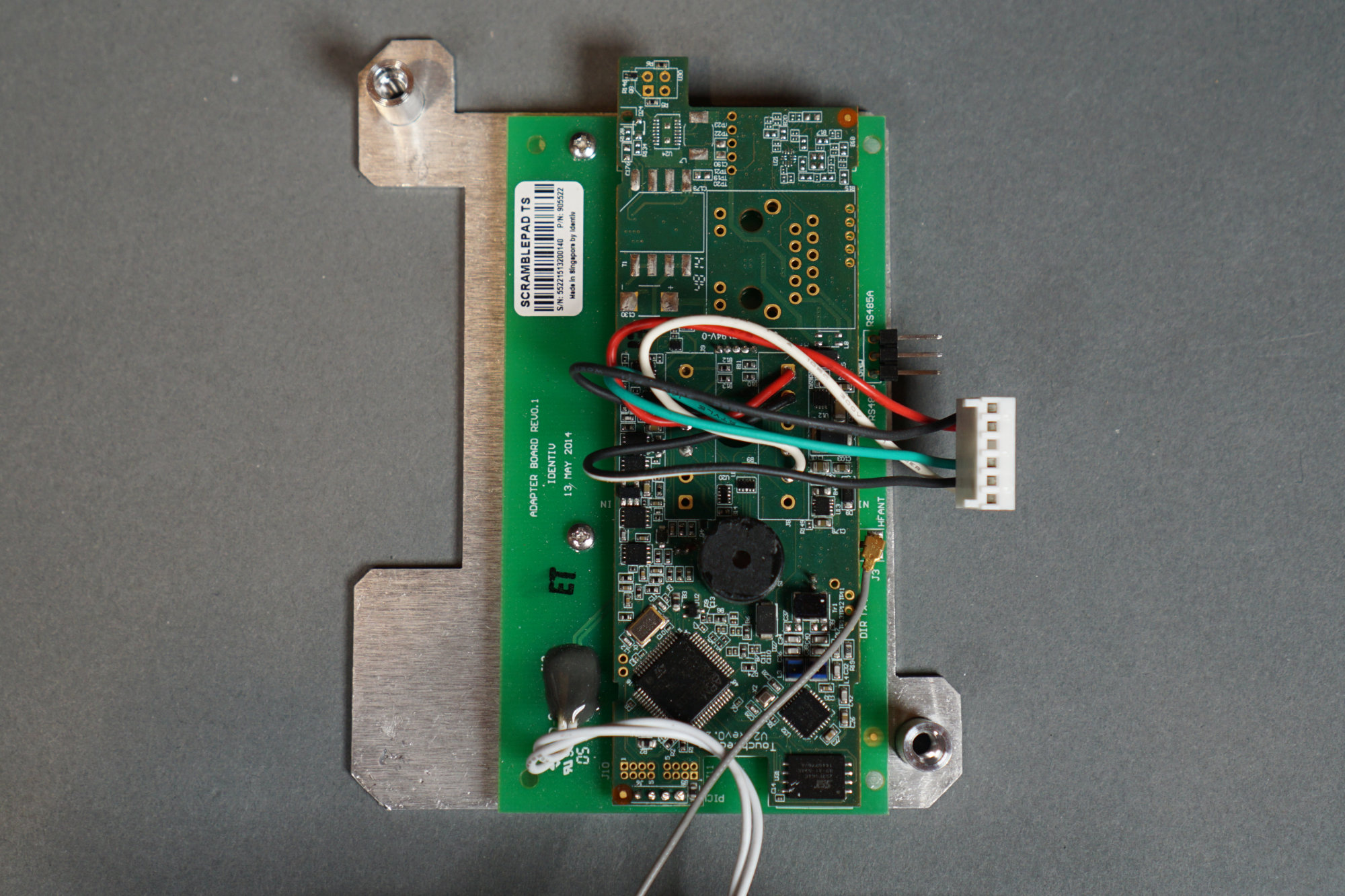
Match2 board.
The photo above is a closer look at the Match2 interface board with the connectors and dip switches. This board combines the card reader and keypad data into a single data stream for the door controller. It also has a five volt power supply for the card readers.
RFID board.
The photo above shows the two RFID boards. They have their own beeper. The 125 kHz coil antenna is connected via the pair of white wires. The 13.56 MHz PCB antenna is connected via the thin gray coax and U.FL connector.
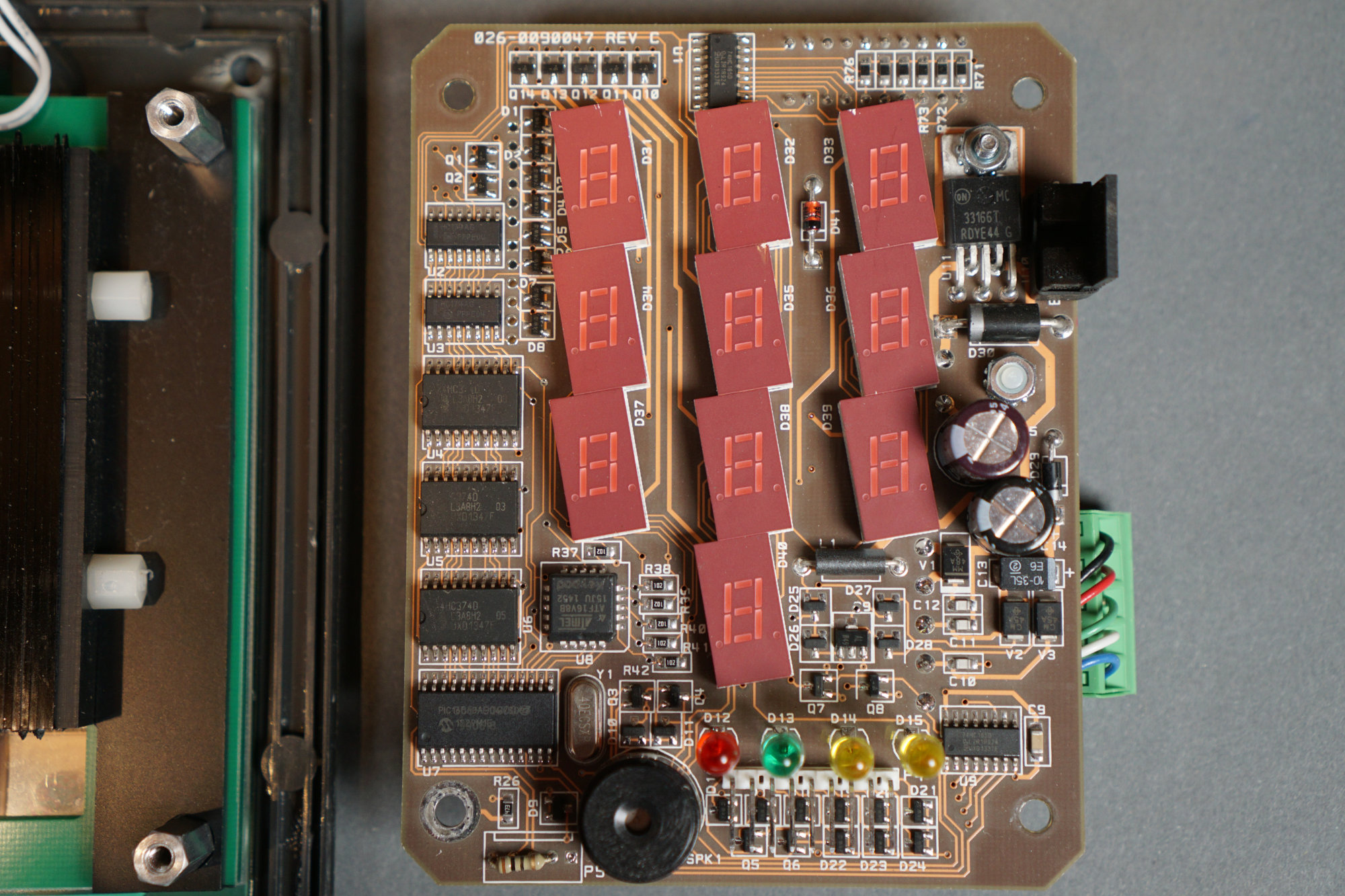
LED display board.
Now for the good stuff. The photo above shows the LED display board. It uses a small one-time-programmable PIC and Atmel CPLD to control everything. The LED displays are mounted off-axis. I suspect the displays are mounted off-axis to provide better visibility through the viewing angle restriction baffles but I have no way of confirming.

Front panel assembly with rubber membrane, resistive touchpad, RFID antennas, and view angle restriction baffles.
Here’s an angled view of the front panel assembly. It provides a better view of the touchpad, acrylic back plate, RFID antennas, and the viewing angle restriction baffles. If you remove the four threaded standoffs, the front panel assembly comes apart too. This is used to replace the outer rubber membrane when its service life is over.
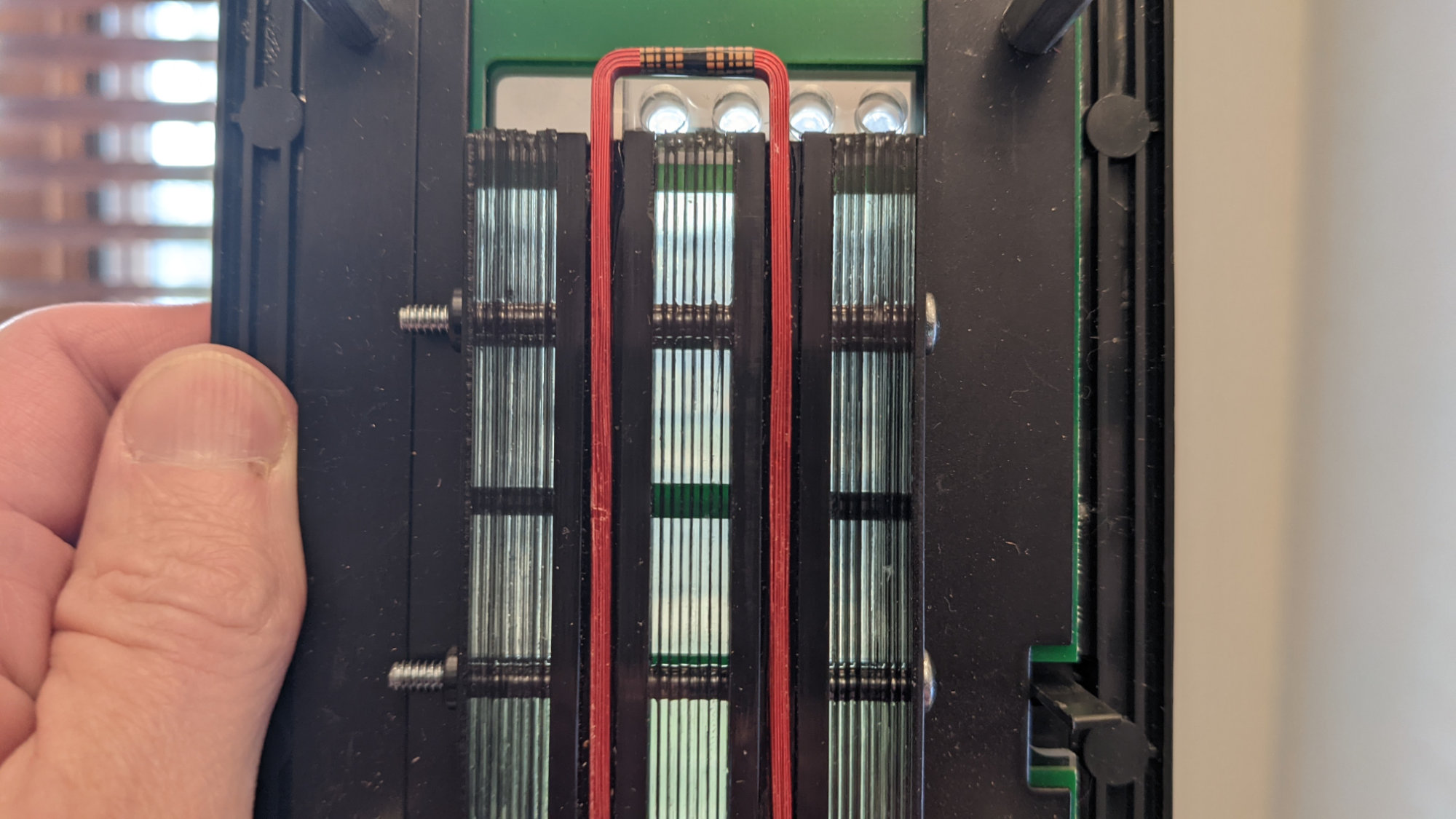
The viewing angle restriction baffles backlit by an open window.
If you hold the front panel assembly up to a light source like an open window, you can see that the baffles are made of thin metal strips and spacers.

The Scramblepad is also available in a high-visibility incandescent version without the viewing angle restriction baffles.
Finally, there’s an incandescent version of the Scramblepad too! This version of the Scramblepad is recommended for outdoor applications in bright sunlight. Instead of seven segment LED displays, this version has flat seven-segment incandescent displays. It also lacks the viewing angle restriction baffles and has a waterproof conformal coating to protect the board from the elements.
The Protocol
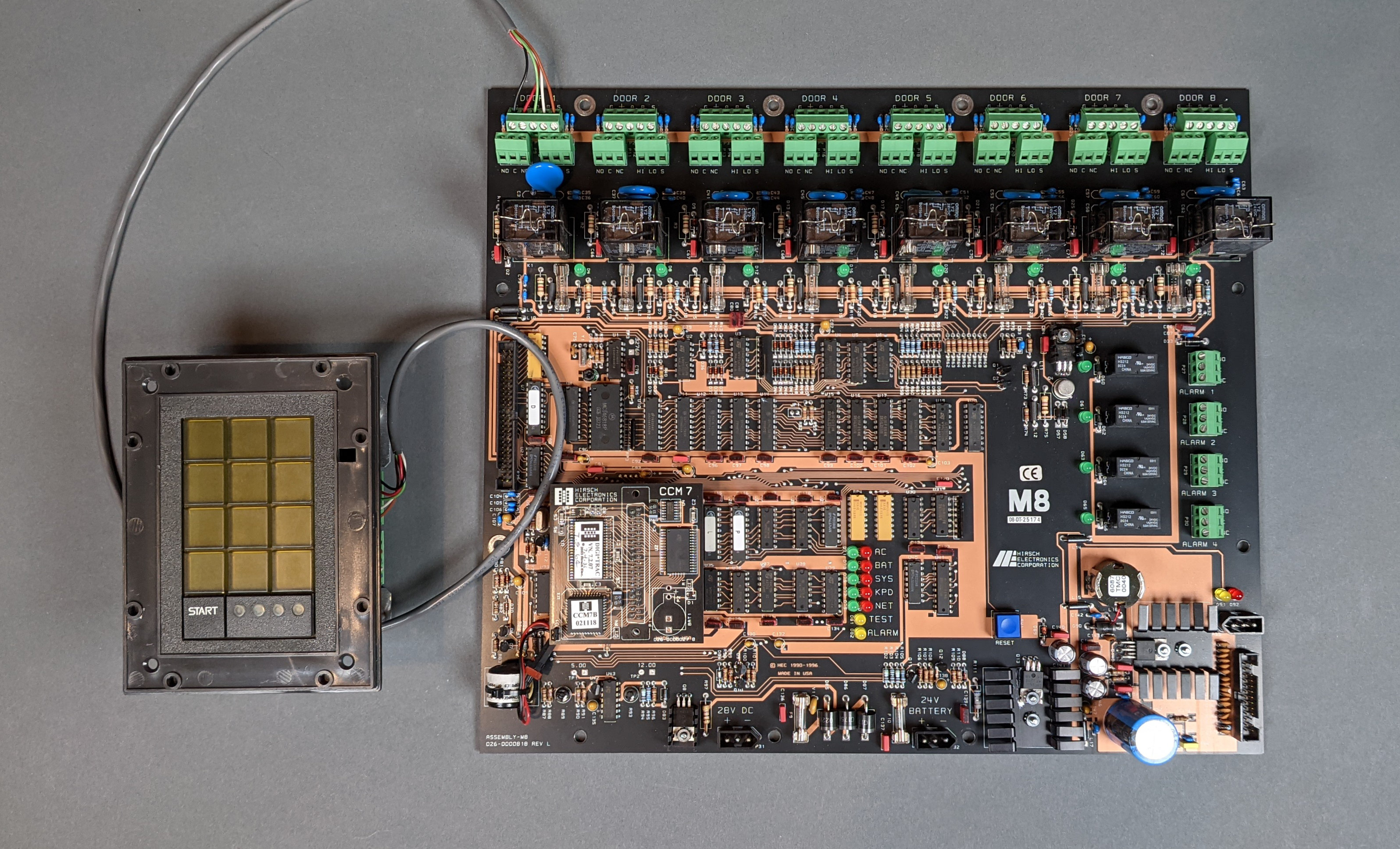
Here’s a Scramblepad and an eight door controller. How they talk to each other was a mystery.
The controller and the Scramblepad talk to each other using a proprietary protocol. This protocol has nothing in common with other protocols commonly used in the access control industry like Wiegand, Open Supervised Device Protocol (OSDP), or even RS-485.
Generally speaking, the controller polls the Scramblepad for data. If the Scramblepad has data from a card read or code entry, it will reply with the data. The controller then replies with an acknowledgement sequence and any further instructions for the Scramblepad. The Scramblepad never initiates communication on its own.
I sussed out most of the protocol by examining the traffic between the keypad board and the Match 2 board within a Scramblepad using a DMM and an oscilloscope. This got me 95% of the protocol and commands. I had to look at the communications between the eight door controller shown above and a Scramblepad to figure out the commands to enable the RFID reader and to start the PIN entry process after a valid RFID card was presented to the reader.
Electrical Signalling
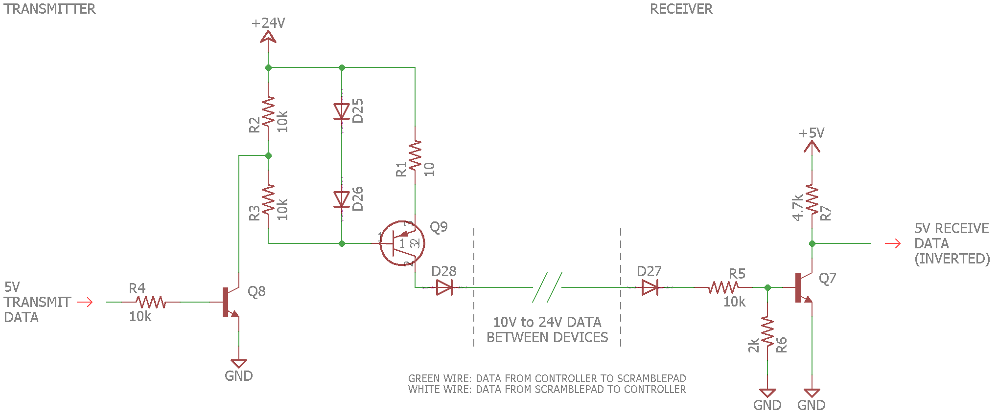
Rough schematic of the transmit and receive circuitry used between the controller and connected Scramblepad(s). There is one instance of this circuitry going from the controller to the Scramblepad and a second instance of this circuitry going from the Scramblepad back to the controller.
The controller and the Scramblepad talk to each other using single-ended signaling capable of multi-drop operation. The A terminals, typically connected using green wires, carry data from the controller to the Scramblepad(s). The B terminals, typically connected using white wires, carry data from the Scramblepad(s) back to the controller.
The signalling on each wire is based on the flow of current. When the line is idle, no current flows between the controller and Scramblepad(s). When the line is transmitting a bit, current flows between the controller and Scramblepad(s).
The transmitter uses a high-side transistor switch to turn on the current. At the receiver, the current causes a low-side transistor switch to turn on and pull the receiver’s microprocessor’s data input pin low. When no current is flowing, the receiver’s transistor switch is off and a pull-up resistor keeps the receiver’s microprocessor’s data input pin high. This causes the 5V data signal at the receiver to be inverted with respect to the data signal at the transmitter.
A bunch of diodes in the transmit and receive circuits limit the current to flowing only in the direction from the transmitter to the receiver. These diodes allow multiple transmitters to reside on a single bus. For example, multiple Scramblepads could connect to a single door’s terminals on the controller board.
The transmitter’s voltage is switched directly from the power supply. The voltages seen on the bus range from about 10 volts with a 12 volt power supply to about 20 volts with a 24 volt power supply.
Framing and Timing
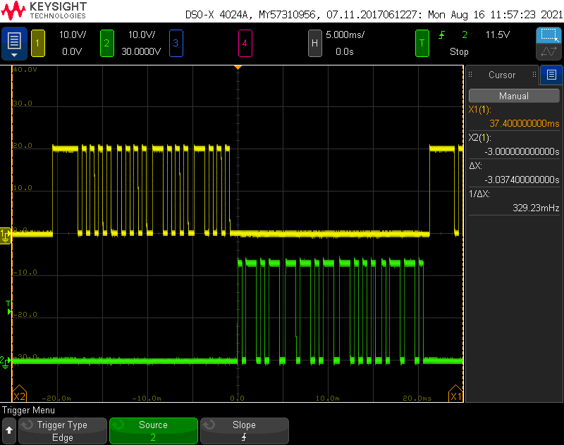
The controller polls the door 8 keypad for any data and the door 8 controller responds that someone entered ‘5’ for their PIN.
Frames of data from the controller to the Scramblepad consist of a start-of-frame bit followed by four nibbles of data. Frames of data from the Scramblepad to the controller consist of three or more nibbles of data without a start bit. All nibbles are sent MSB first.
Each bit type is denoted by the length of time the data signal is high. Start-of-frame bits are the longest duration bits, zeros are the shortest duration bits, and one bits fall between the two. It’s basically like Morse code where a dot is a zero and a dash is a one and there’s an extra super long dash (—) to indicate the start of the message. The gap between bits within a nibble is about the length of a zero bit. The gap between nibbles is slightly longer. The bit times are summarized in the following table:
| Bit Type | Duration |
|---|---|
| Start of Frame | 2780 μs |
| Zero Bit | 480 μs |
| One Bit | 1160 μs |
| Bit Gap | 440 μs |
| Nibble Gap | 678 μs |
In the scope trace at the top of this section, the yellow trace is the controller polling the keypad for data and the green trace is the keypad responding to the controller with some data. You can see the different timing of each bit and the gaps between the bits. In this case, the controller is sending 0x0088 to the keypad and the keypad is responding with 0x5d86 to the controller.
Messages from the Controller to the Scramblepad

The yellow trace is the controller polling the keypad for data. The two control nibbles are 0x0 and 0x0, the door number is 0x8, and the checksum is 0x8.
Messages are sent from the controller to the Scramblepad to poll the Scramblepad for data and to control Scramblepad features. All messages from the controller to the Scramblepad consist of a start-of-frame bit and four nibbles of data.
The first two nibbles are control nibbles that control the Scramblepad’s features. The third nibble is the door number which must match the door number set on the DIP switches on the back of the Scramblepad. The fourth nibble is a checksum nibble.
| Nibble | Definition |
|---|---|
| 0 | Control nibble 0. |
| 1 | Control nibble 1. |
| 2 | Door number from 0x1 to 0xF for doors 1 to 15 or 0x0 for door 1. |
| 3 | Checksum. Choose this nibble such that the sum of all four nibbles in the message equals 0 modulo 16. |
Regular Polling / Data Request Messages
The primary and most frequent message sent from the controller to the Scramblepad is a regular polling message. This message is sent roughly four times per second and is used to control the LEDs, beeper, and other features of the Scramblepad and to request the Scramblepad to return the card ID of a presented card or the PIN entered by the user. The bits in this message are defined as follow.
| Control Nibble 0 | Control Nibble 1 | ||||||
|---|---|---|---|---|---|---|---|
| 8 | 4 | 2 | 1 | 8 | 4 | 2 | 1 |
| Right Yellow LED | Left Yellow LED | Green LED | Red LED | Beeper | Shift / ACK | Silent | Non-Random |
The two control nibbles are followed by the door number and checksum nibbles as described above.
Setting a bit in the message enables that feature on the Scramblepad. For example, to turn on the red LED and beeper for a half second, two poll messages with 0x18 in the first two nibbles are sent. The third poll message would have a control value of 0x00 to turn off the red LED and beeper. Since these messages are sent every 250ms, that would turn on the red LED and beeper for a half second.
Setting the silent bit in poll messages puts the Scramblepad in silent mode where it does not beep when start is pressed or a digit is entered. Setting the non-random bit in poll messages puts the Scramblepad in non-random mode and the digits will be arranged in order like on a telephone keypad when the user presses the start key. These modes are exited by sending poll messages with these bits cleared.
Acknowledgement and Control Messages
In addition to the regular polling message defined above, there are three special messages that may be sent from the controller to the Scramblepad.
The first special message is an acknowledgement message. Whenever a reply from a Scramblepad is received, two acknowledgement messages spaced 5 ms apart are sent from the controller to the Scramblepad. These messages are four nibbles long and consist of the control value 0x04 followed by the door number and checksum.
The second special message enables the RFID reader on Scramblepads equipped with an RFID reader. This message is four nibbles long and consists of the control value 0x15 followed by the door number and checksum. This message needs to be sent at least once after the Scramblepad has booted. It is periodically sent during operation in case the Scramblepad loses power or reboots.
The third special control message is used to trigger the randomization of the digits and the start of PIN entry when a valid RFID card is presented the reader. This message is four nibbles long and consists of the control value 0x16 followed by the door number and checksum. This message is sent after receiving and acknowledging the ID of the presented card or key fob from the Scramblepad.
Messages from the Scramblepad to the Controller
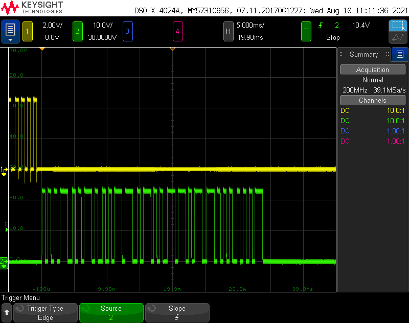
The green trace is the keypad responding to a poll from the controller. In this case, it’s responding with the PIN 1-2-3-4 then the end of data character 0xd, the door number 0x8, and the checksum 0x1. This capture is from before my software replied to the keypad with the required ack messages.
The Scramblepad never responds to the controller unless it has been polled and the door number in the polling message matches the DIP switches set on the back of the Scramblepad. The Scramblepad usually only responds to the controller when it has data to send, but about once every five seconds, it will respond with an “I’m alive” response.
Responses from the Scramblepad back to the controller consist of three or more nibbles without a start bit. While the number of nibbles in a response varies, the last three nibbles always have the same purpose. The third to last nibble is a response type code. The second to last nibble is the door code. The last nibble is a checksum. The last three nibbles form a unique pattern that can be used to determine when a complete response has been received by the controller.
All responses from the Scramblepad to the controller should be followed by the controller sending the double ACK sequence described in the previous section back to the Scramblepad.
The “I’m Alive” Response
The periodic “I’m alive” response from the Scramblepad is three nibbles long. The first nibble is 0xE. The second nibble is the door number. The third nibble is a checksum. This response is sent back to the controller in response to a poll message every four to five seconds and can be used by the controller to verify a Scramblepad is connected. As an example, the “I’m alive” response for Door #1 would be [ 0xE 0x1 0x1 ].
The PIN Response
After a user has entered a PIN, the Scramblepad will respond to the controller’s poll request with the value of the user’s PIN encoded as a binary coded decimal number. The PIN response consists of the BCD-encoded PIN followed by 0xD, the door number, and a checksum. The length of the message is N+3 nibbles where N is the length of the PIN entered by the user.
For example, if the user entered a four-digit PIN, the length of the response will be seven nibbles. If the entered PIN were 1-2-3-4 on the Scramblepad for Door #1, the seven-nibble response would be [ 0x1 0x2 0x3 0x4 0xD 0x1 0x8 ].
The Card ID Response
When a card is presented the RFID reader embedded in the Scramblepad, the Scramblepad will respond to the controller’s poll message with 13 nibbles.
The first two nibbles will be 0xC and 0x1. This is followed by an 8-nibble BCD-encoded decimal representation of the card’s unique ID number. Finally, the response ends with 0xD, the door number, and a checksum calculated over all the nibbles.
For example, if the decimal value of the card’s ID number is 12345678 and the Scramblepad is for Door #1, the Scramblepad will respond with [ 0xC, 0x1, 0x1, 0x2, 0x3, 0x4, 0x5, 0x6, 0x7, 0x8, 0xD, 0x1, 0x1 ].
I didn’t bother to figure out the mapping of facility codes and card numbers to their decimal values. It’s easier to scan the card with the debugger attached to the PIC and copy/paste the response into the software where it’s needed to authenticate the card.
Miscellaneous Messages
Some longer messages are periodically sent between the controller and Scramblepad that start with 0xC2. These are likely software version numbers or hardware capability messages that can be ignored.
Card Presented Messaging Example
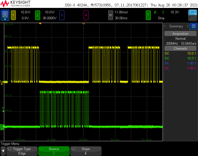
Scope traces showing communications after a card is presented. Poll request, poll response with card ID, two acks, then message to enable PIN entry.
The scope traces above show the interactions between the controller and the Scramblepad when an RFID card is presented to the reader. The yellow trace is the controller. The green trace is the Scramblepad.
- The controller sends a poll message to the Scramblepad, 0x001F.
- The Scramblepad replies with the card ID number, oxC1<8 digits>D1<cksum>.
- The controller responds with an immediate ack, 0x041B, then a second ack 5 ms later, also 0x041B.
- Since this card was in the controller’s database, the controller sends 0x1618 to the Scramblepad to prompt the user to enter their PIN.
Code Entry Messaging Example
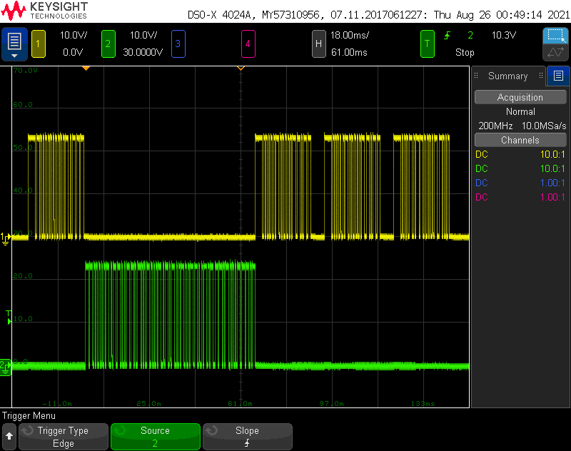
Scope traces after a PIN is entered on the keypad. Poll request, poll response with PIN, and two acks,
The scope traces above show the interactions between the controller and the Scramblepad when a PIN of 1-2-3-4 is entered by a user. The yellow trace is the controller. The green trace is the Scramblepad.
- The controller sends a poll message to the Scramblepad, 0x001F.
- The Scramblepad replies with the PIN entered by the user, ox1234D18.
- The controller responds with an immediate ack, 0x041B, then another ack 5 ms later, also 0x041B.
Prototyping a Simple Controller
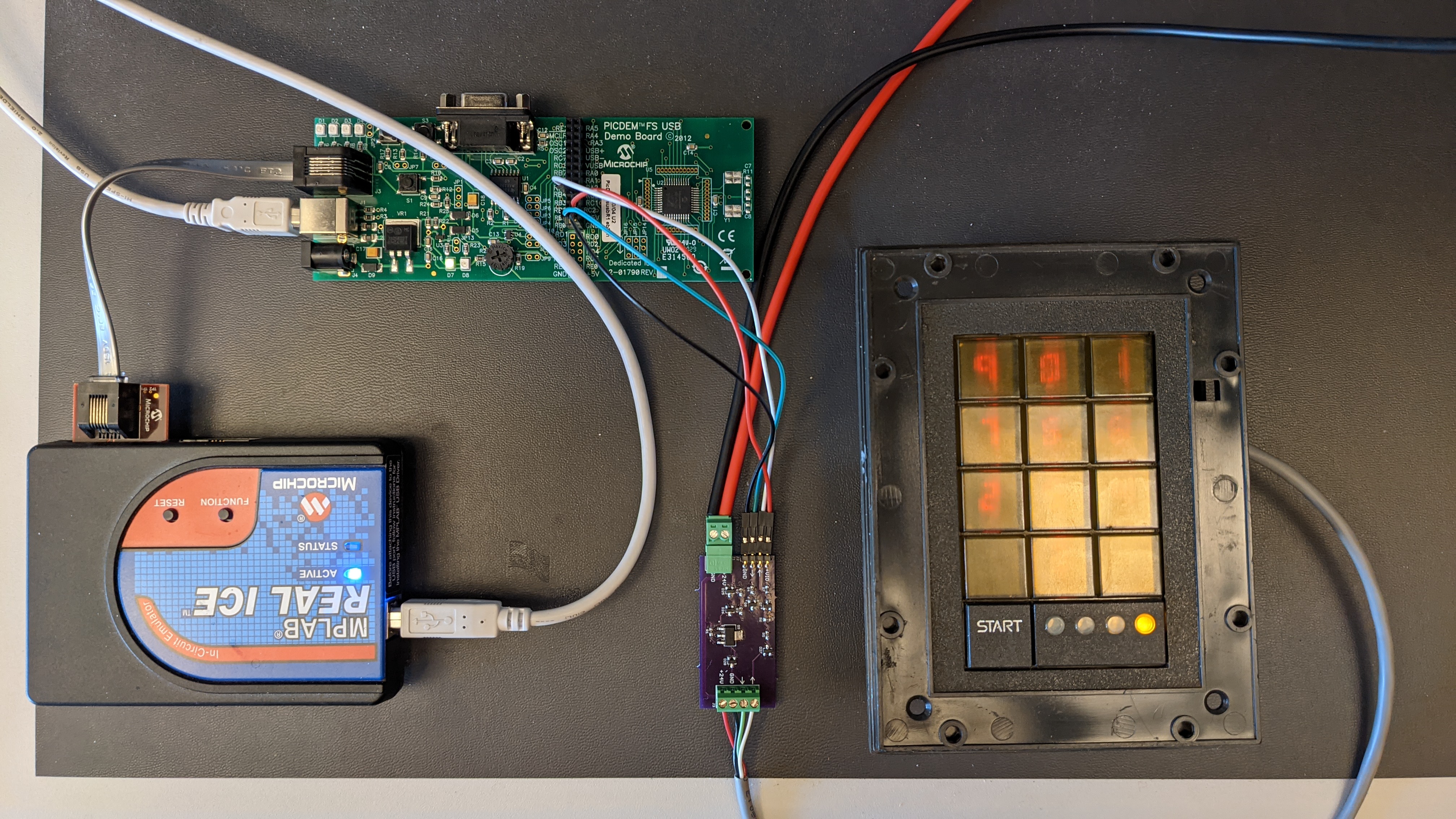
The prototype hardware including a small board to test the design of an electrical interface to the Scramblepad.
Now that I had a basic understanding of the signalling and messaging between the controller and the Scramblepad, it was time to prototype my own simplified controller for the Scramblepad. The prototype would be used to test the electrical interface to the Scramblepad, to develop software, and to refine the algorithms for controlling and monitoring the Scramblepad.
The prototype setup consists of a Microchip PICDEM FS USB demonstration board with a PIC18F45K0 microcontroller, a Scramblepad with an integrated RFID reader and Match2 interface board, and a small interface board to connect the demo board to the Scramblepad. The interface board passes power from a bench supply through to the Scramblepad and translates the PIC’s 5V IO to the Scramblepad’s IO levels. I used a Microchip REAL ICE in-circuit emulator to program and debug the PIC18F45K50 micro on the demo board.
The Interface Board

The board used to connect the 5V PIC microcontroller to the Scramblepad’s 24V bus.
The photo above shows a closeup of the interface board used to connect the PIC demo board to the Scramblepad. The top left 0.1″ header connects to the demo board’s power, ground, and two IO pins. The bottom left Phoenix connector connects to a bench power supply set for 24V. The right connector connects to the Scramblepad.
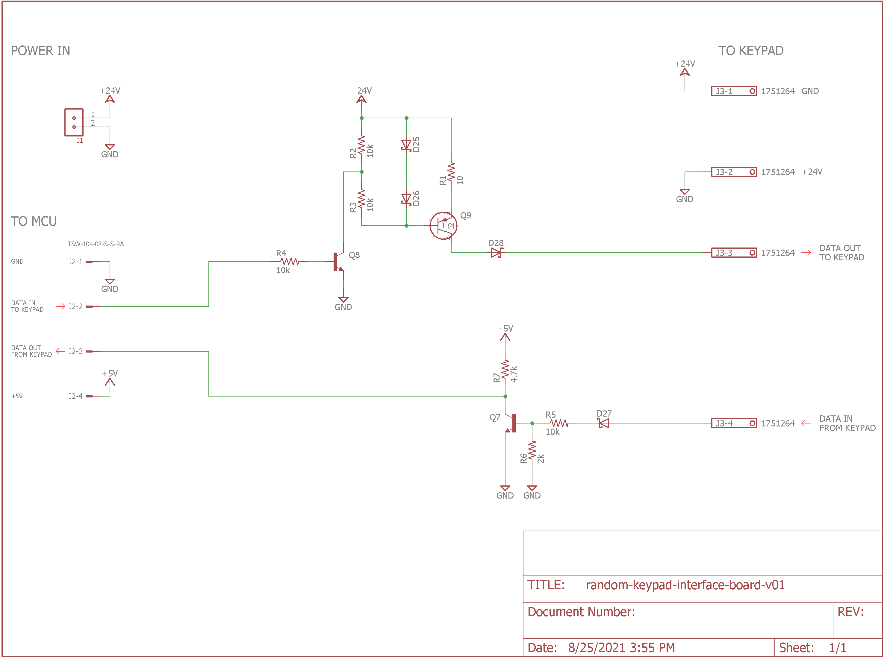
Schematic for the electrical interface test board.
The circuitry on the interface board is shown in the schematic above. It’s the same circuitry shown in the electrical signalling section of the protocol section of this document with some connectors added to it. I built this board to test the interface circuitry and make sure it worked before building a larger, more expensive board. I also built it to connect the demo board to the Scramblepad for software development.
Software for Sending Messages to the Scramblepad
The prototype software needs to do two things: send messages to the Scramblepad and received messages from the Scramblepad. To send messages to the Scramblepad, I decided to use the PIC18F45K50’s timer 0 interrupt to time and send the varying width pulses.
I initialized the timer then based on the system clock frequency and chosen prescaler, I calculated some constants corresponding to the different lengths of the pulses and gaps.
#define SOF_TIME     0xF7DA     // 2780 us
#define GAP_TIME     0xFEB5     //  440 us
#define ZERO_TIME    0xFE97     //  480 us
#define ONE_TIME     0xFC99     // 1160 us
#define NIB_GAP_TIME 0xFE03     //  678 us
#define REPEAT_TIME  0xF159     // 5000 us
Since I’m doing everything at interrupt time, I needed a simple state machine to track where I was at in the protocol and decide what to do next at each interupt. I needed a total of five states to send each type of bit or gap.
#define SEND_IDLE    0
#define SEND_SOF     1
#define SEND_SOF_GAP 2
#define SEND_GAP     3
#define SEND_BIT     4
Finally with the defines for the lengths of the pulses, the lengths of the gaps, and the state machine states, I could write my send routine and interrupt handler. The following code is called from the main line of the code to send some nibbles to the Scramblepad. It initializes the state machine to transmit the start of frame bit followed by the data bits then sets timer 0 to expire and enter its interrupt handler almost immediately.
void SendBits (void)
{
    // set up to transmit bits
    sendState = SEND_SOF;
    sendBit = 0;
    nextTmr0Hi = SOF_TIME >> 8;
    nextTmr0Lo = SOF_TIME;
    nextTmr0Bit = 1;

    // clear timeout timer flag
    flag5ms = 0;

    // initialize timer 0 to interrupt almost immediately
    T0CONbits.T08BIT = 0;
    TMR0H = 0xFF;
    TMR0L = 0xFF;
    INTCON2bits.TMR0IP = 0;
    INTCONbits.TMR0IF = 0;
    INTCONbits.TMR0IE = 1;
    T0CON = 0x93;
}
This is the timer 0 interrupt handler that does the bulk of the work. It sets the GPIO output to the correct state (0 or 1), sets the timer’s next expiration time, then clears the timer interrupt flag. After doing this time senstive processing, it looks at the state machine state to decide what to do next.
void TMR0_InterruptHandler (void)
{
    uint8_t bitValue;

    LATBbits.LATB0 = nextTmr0Bit;
    TMR0H = nextTmr0Hi;
    TMR0L = nextTmr0Lo;
    INTCONbits.TMR0IF = 0;

    switch (sendState) {
        case SEND_IDLE:
            break;
        case SEND_SOF:
            sendState = SEND_SOF_GAP;
            nextTmr0Hi = GAP_TIME >> 8;
            nextTmr0Lo = GAP_TIME;
            nextTmr0Bit = 0;
            break;
        case SEND_SOF_GAP:
        case SEND_GAP:
            if (sendBit >= numBitsToSend) {
                sendState = SEND_IDLE;
                INTCONbits.TMR0IF = 0;
                INTCONbits.TMR0IE = 0;
                T0CONbits.TMR0ON = 0;

                // clear number of received bits and nibbles
                rxBits = 0;
                rxNibbles = 0;

                // clear timer 1, clear timer 1 flag, enable timer 1 interrupts
                TMR1H = 0;
                TMR1L = 0;
                PIR1bits.TMR1IF = 0;
                PIE1bits.TMR1IE = 1;

                // read port b, clear ioc interrupt flag, enable ioc interrupts
                bbits = PORTB;
                INTCONbits.IOCIF = 0;  // clear flag
                INTCONbits.IOCIE = 1;  // enable interrupt
            } else {
                bitValue = (theBitsToSend[sendBit >> 3] >> (7-(sendBit & 7))) & 0x1;
                nextTmr0Bit = 1;
                if (bitValue) {
                    nextTmr0Hi = ONE_TIME >> 8;
                    nextTmr0Lo = ONE_TIME;
                } else {
                    nextTmr0Hi = ZERO_TIME >> 8;
                    nextTmr0Lo = ZERO_TIME;
                }
                sendState = SEND_BIT;
                sendBit++;
            }
            break;
        case SEND_BIT:
            sendState = SEND_GAP;
            if ((sendBit & 3) == 0) {
                nextTmr0Hi = NIB_GAP_TIME >> 8;
                nextTmr0Lo = NIB_GAP_TIME;
            } else {
                nextTmr0Hi = GAP_TIME >> 8;
                nextTmr0Lo = GAP_TIME;
            }
            nextTmr0Bit = 0;
            break;
    }
}
After a complete message has been sent, timer 1 is set to expire and generate an interrupt after roughly 5 ms. This interrupt is used to time the ACK messages sent in response to a reply from the Scramblepad. It’s also used to time out when a Scramblepad does not respond to a message.
I used an oscilloscope to debug the send routine then connected the PIC demo board to the Scramblepad using the evaluation board. I set up the main line of the code to blink the two yellow LEDs back and forth on the Scramblepad. When the yellow LEDs started blinking and I periodically received poll responses from the Scramblepad, I knew my code to send messages to the Scramblepad was working.
Software for Receiving Messages from the Scramblepad
I used the PIC18F45K50’s interrupt on change feature to receive messages from the Scramblepad. Every time the Scramblepad changes the state of the GPIO input on the PIC, this IOC interrupt handler is called.
void IOC_InterruptHandler (void)
{
    uint16_t timervalue;
    uint8_t rxBit;

    bbits = PORTB ^ 0x10;
    timervalue = TMR1L;
    timervalue |= (uint16_t)TMR1H << 8;
    TMR1H = 0;
    TMR1L = 0;

    // look for a falling edge
    if ((bbits & 0x10) == 0) {
        // falling edge detected, now determine if a zero or a one
        // (480+1180)/2 * 12e6 = 9960
        rxBit = (timervalue >= 9960) ? 1 : 0;

        // echo decoded bit on LATB1
        LATBbits.LATB1 = rxBit;

        // shift received bit into nibble holding register and increment count of bits received
        rxNibble = ((rxNibble << 1) | rxBit) & 0xf;
        rxBits++;

        // once four bits are received, that's a nibble save it off
        if (rxBits == 4) {
            rxBits = 0;
            rxData[rxNibbles] = rxNibble;
            rxNibbles++;

            // shift last three receive nibbles
            rxn0 = rxn1;
            rxn1 = rxn2;
            rxn2 = rxNibble;

            if (rxNibbles >= 3) {           // if at least three nibbles, start looking for end of data
                if (((rxn0 == 0xd) && (rxn1 == 0x01)) ||
                    ((rxn0 == 0xe) && (rxn1 == 0x01))) {
                    // disable ioc interrupts
                    INTCONbits.IOCIE = 0;
                    // disable timer1 interrupts
                    PIE1bits.TMR1IE = 0;
                    // notify main loop that data is available
                    acksNeeded = 2;
                }
            } else if (rxNibbles >= 32) {   // holding register is full
                // disable ioc interrupts
                INTCONbits.IOCIE = 0;
                // disable timer1 interrupts
                PIE1bits.TMR1IE = 0;
                // notify main loop that data is available
                acksNeeded = 2;
            }
        }
    }

    INTCONbits.IOCIF = 0;  // clear flag
}
This code runs in the background. It receives each bit, determines if the bit is a zero or one, then saves off the received nibbles to memory. Once a matching set of end of data nibbles are received, it sets acksNeeded to 2 to signal the main line of code that a complete message has been received. This code has the door number fixed at 1 and does not check the checksum nibble.
The main line of code can then process the message from the Scramblepad and send the required ACKs back to the Scramblepad. If the message includes a prox card ID, the main line code can see if the card is valid and tell the Scramblepad to scramble the digits and get a PIN from the user. If the message includes a PIN, the main line code can see if the PIN matches the previously presented prox card or not and then either allow or deny access to the door.
What’s Next?
This concludes part 1 of this two part series of blog posts. In Part 2, we’ll take what we’ve learned in Part 1 and build a simple door controller similar to the door controller that I use with the RFID reader and my mountain bike helmet.