
In this project, I build what is quite possibly the world’s simplest (and least intelligent) door access controller to let me open and close my garage door using my mountain bike helmet. We’ll take a look at my motivation for the project, review some available RFID readers, pick a reader, then design and program the simple access controller. The simple access controller will receive the card ID from the RFID reader, compare the ID against a list of authorized cards, and make the decision to activate the garage door opener or not. Afterwards, we’ll briefly talk about the security of the system and include some ideas on how to improve the project.
Motivation
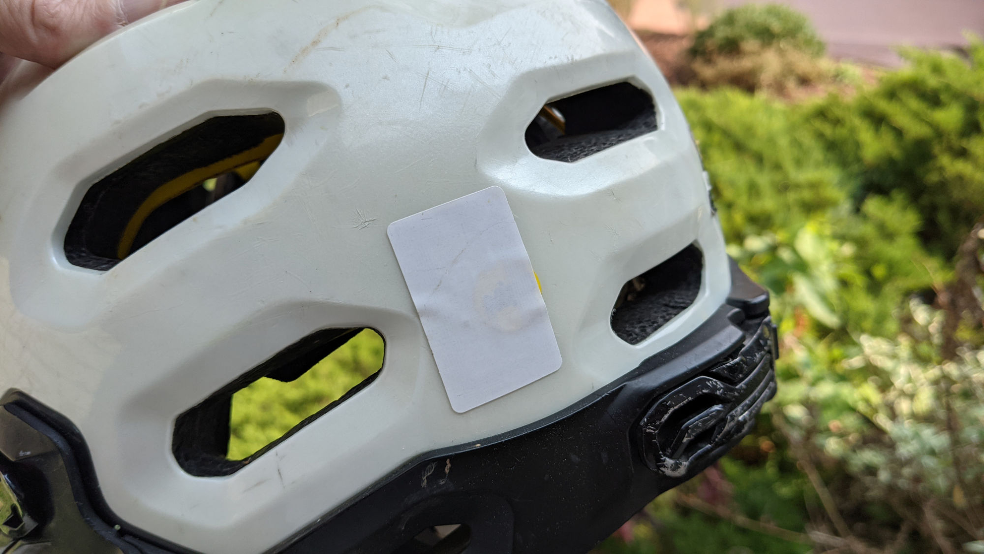
The 13.56 MHz NTAG203 RFID sticker on the back of my helmet.
My primary motivation for this project was to have a quick way to get into the garage after riding my bike in the hills and around town. Most of my neighbors have simple keypads where you type in a numeric code and the garage door opens or closes. This would be the easy route and I could have gone down this route too. But, just like with mountain biking, the major downside to picking the easy route is you don’t improve your skills.
As usual, I decided to go down the gnarly route. My first thought was to put an RFID card in my hydration pack so I could hold my pack up against a reader and open or close the door. After pondering this for a while, I discovered they make thin RFID stickers. Inspired by dirt bike enduro races that use barcodes on helmets to time racers, I had the thought to stick an RFID sticker to my helmet to open or close the door, and, voila, the project was born!
RFID Technology
The first step in an RFID project is to pick the RFID technology to use. RFID technology is primarily divided into categories by the frequencies used to communicate between the RFID reader and the RFID token. These frequencies are 125 kHz, 13.56 MHz, and UHF frequencies between 860 MHz and 960 MHz.
Regardless of frequency, they all work on the same basic concept whereby the reader uses a coil to induce a current in a token that powers a chip that can receive a signal, decode the signal, process the signal, encode a response, and transmit the response back to the reader. The simplest RFID chips just transmit their serial number back to the reader. Other chips can perform complex cryptographic operations to establish an encrypted and authenticated link between the reader and the token and then use the data exchanged back and forth to update their non-volatile memory.
125 kHz Tech
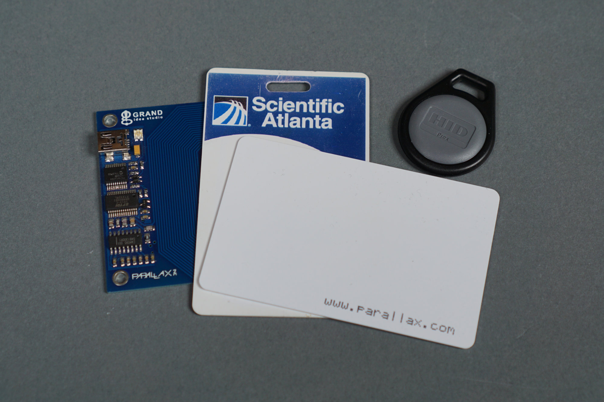
Some examples of 125 kHz RFID technology: a Parallax reader and cards, an old SciAtl work badge, and an HID Global keyfob.
125 kHz RFID technology is the oldest technology in common use. The read range is limited to a few centimeters. These RFID tokens are often used for getting into corporate office buildings, parking garages, and apartment common areas. These tokens transmit a fixed 26, 32, or 37 bit code.
The HID Global cards used for access to office buildings typically transmit 26 bits or 37 bits. Some other cards, like the Parallax card in the photo above, transmit 32 bits. All of the 125 kHz cards are inexpensive but they’re not secure. A quick perusal of Amazon, eBay, or AliExpress shows all sorts of devices for cloning and duplicating these cards.
13.56 MHz Tech
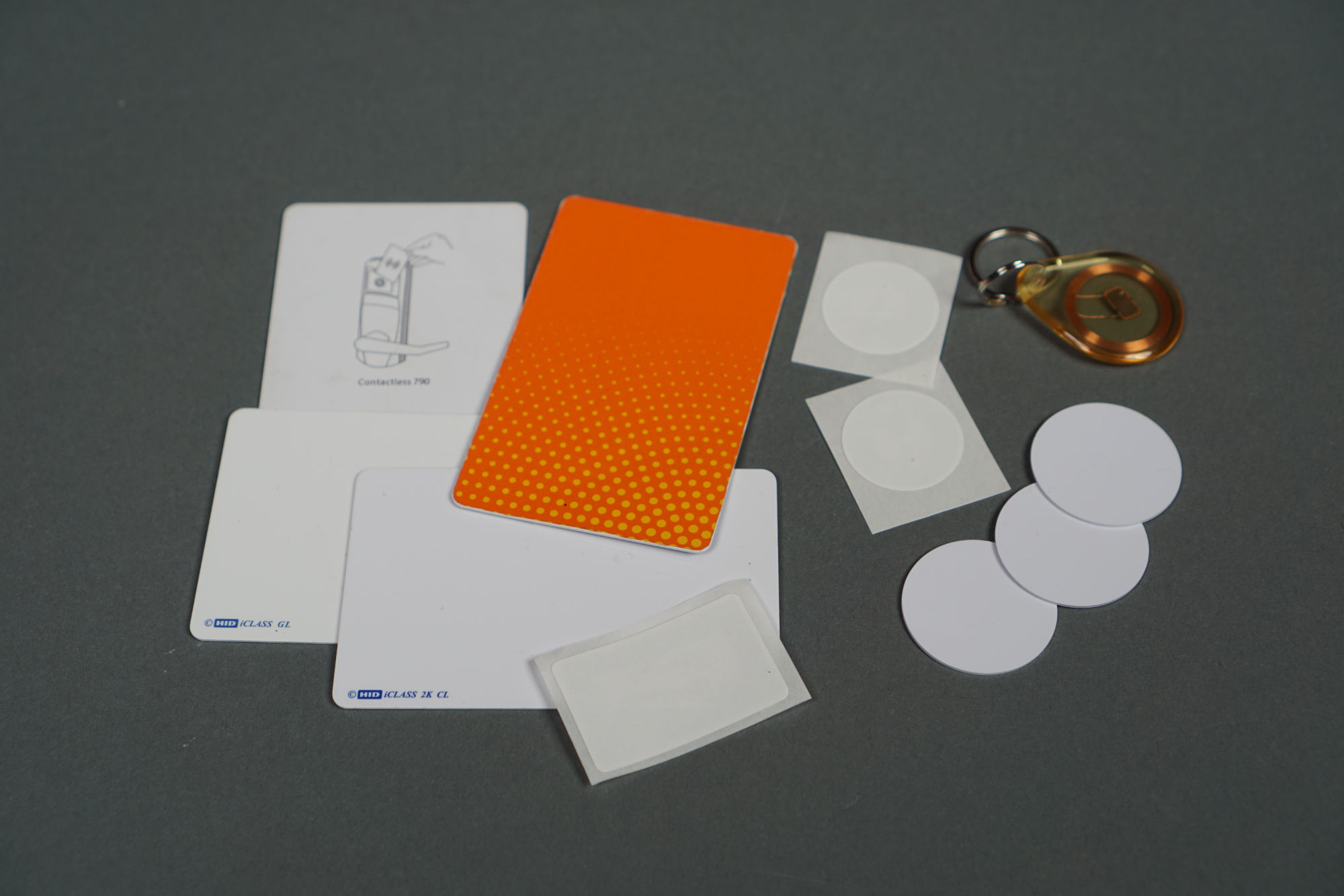
Some example 13.56 MHz RFID cards, stickers, key fobs, and tokens.
13.56 MHz RFID tags are the most widely used tags. They have a read range from a few centimeter to about half a meter. They’re used for hotel room keys, traditional proximity-based access control cards, stored value cards, asset tracking, and transit fare cards. The 13.56 MHz tags I have are divided into two groups: HID Global’s iClass cards and cards that follow the ISO14443 standard.
The iClass cards can be read only by HID multiClass or iClass readers (more on these readers later). The ISO14443 cards can be read on most readers including some but not all HID multiClass and iClass readers.
Some examples of ISO14443 standard cards include cards sold under the names MIFARE, NTAG, and DESFire. This page has some details on the various RFID card standards. The HID cards have 26 or 37 bit unique IDs. The ISO14443 cards have either 4 or 7 byte unique IDs (UIDs).
13.56 MHz Tech Security
The security of 13.56 MHz RFID cards runs the gamut from very little like the 125 kHz RFID cards to very sophisticated with encrypted tunnels and mutual authentication of the reader and card. Applications that only use the ISO14443 UID for authentication basically have the same security as the 125 kHz technology RFID tokens. “Magic” 13.56 MHz RFID chips are available that permit re-writing their UID. These chips allow the UID from one card to be cloned into the “magic” card. These chips are used in the Dangerous Things RFID implants.
At the other end of the security scale are technologies like HID Global’s iClass SEOS readers and cards. A customer’s key is embedded in a hardware security element inside the reader. Each card contains a diversified key that is derived from the customer’s key and the card’s UID. The reader computes its own value of the diversified key then that common key is used to mutually authenticate the card and reader to each other. If the authentication check passes, the reader beeps twice instead of once and the UID of the card is forwarded to the access controller.
The NXP MIFARE DESFire cards are capable of similar authentication and encryption as HID Global’s iClass SEOS card but are usually used for applications like stored value cards and transit fare cards. Using a reader breakout board like Adafruit’s PN532 or M5Stack’s MFRC522 miniature reader (both discussed in the next section) along with the NXP TapLink SDK or the open source libnfc library, it should be possible for even a hobbyist to build their own application with the same level of security as the HID Global iClass SEOS system. That project, however, is currently left to the reader.
UHF Tech
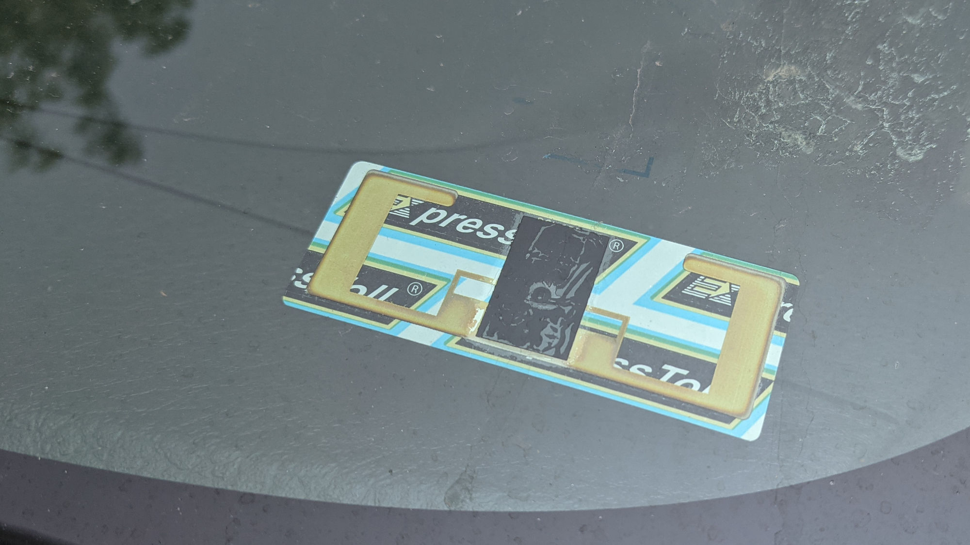
A UHF RFID toll transponder sticker on the the inside of my windshield for E-470’s ExpressToll system.
The last type of tag I looked at were EPC Global Class1 Gen2 UHF RFID tags. These are available in sticker form and are typically used for toll roads, race timing, and capital asset inventory applications. The stickers can be read at high speeds and at a distance of several meters with the right antennas. For inventory applications, hundreds of stickers within the read area can be read simultaneously. I ruled these out due to the cost of the readers and that I didn’t want to trigger my garage door from more than a few centimeters.
RFID Readers
After learning about the available RFID tag technology and available products, I decided to use a 13.56 MHz ISO14443 sticker for the back of my bicycle helmet. They’re cheap, readily available from multiple sources, and compatible with most 13.56 MHz RFID readers. The next step was to pick a reader.
Impinj UHF Readers

Impinj Raceway UHF RFID readers. Photo from https://www.impinj.com/products/readers/impinj-speedway
Let’s start with the highest end and most expensive readers. Readers like the Impinj reader shown above operate in the UHF frequency band. These readers are used for high-speed, long-distance applications. They use external antennas that can be focused to precisely define the read area and they can read multiple tags within in the read area simultaneously. The Impinj readers start at about $1000 without antennas. I don’t have one. It wouldn’t work with the 13.56 MHz sticker I chose for my helmet anyway. Maybe someday.
Adafruit PN532 NFC/RFID Controller Breakout Board
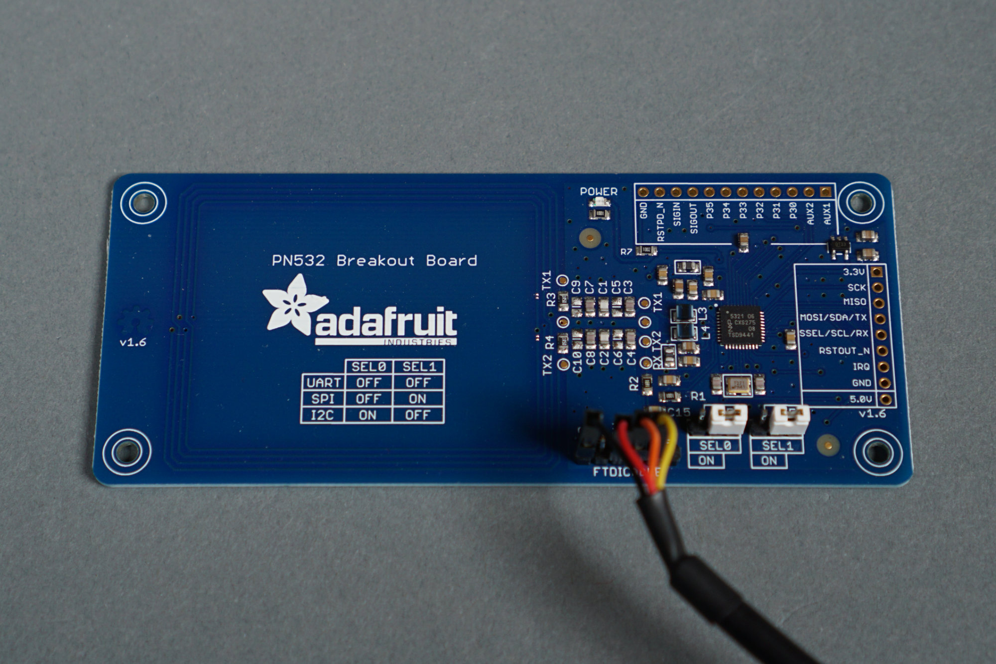
The Adafruit PN532 breakout board.
Next up is the Adafruit PN532 NFC/RFID controller breakout board. It’s a versatile breakout board for experimenting with the NXP PN532 RFID reader/writer IC. It lets you read and write 13.56 MHz ISO14443-compliant contactless cards from any system supporting 3.3V I2C, SPI, or UART communications.
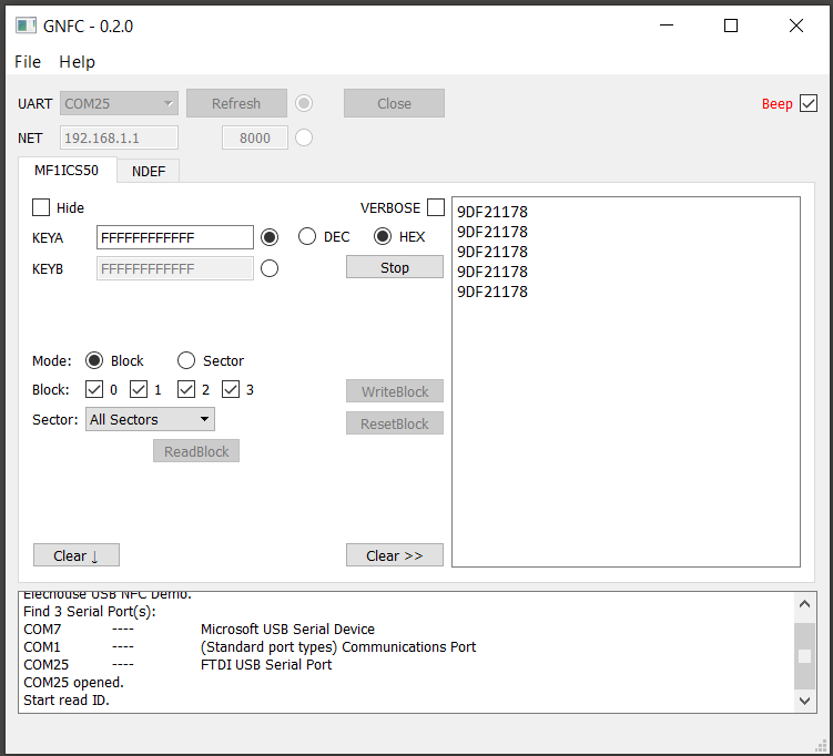
The main screen of the GNFC app for Windows and the PN532 reader IC.
Adafruit has a guide to using their breakout board with Arduino or CircuitPython. I didn’t want to develop another embedded system just for testing so I dug around and found an app called GNCF on Github that was adequate for testing the board and reading a few cards using a UART connection from a PC.
I decided not to use this board for my project because it’s physically large and I needed something that would be easy to waterproof and place on the exterior of the house. Some day I’d like to revisit this board to see if I can get mutual authentication and encryption working using MIFARE DESFire cards and libnfc. It also looks like this board may be able to read HID iClass cards (but not iClass SE cards) using libnfc.
M5Stack MFRC522 Mini RFID Reader/Writer Unit

With an M5Stack Atom, an M5Stack four relay board, and an M5Stack RFID reader, a complete RFID control project can be built with no soldering.
The second RFID reader I researched and experimented with is the M5Stack MFRC522 mini RFID reader/writer unit. It’s small and inexpensive at $12.50. It’s based on the RC522 RFID module and uses I2C to communicate with a host microprocessor. M5Stack has an Arduino library and example Arduino sketch on their website to demonstrate reading of 13.56 MHz ISO14443 card UIDs using the module.
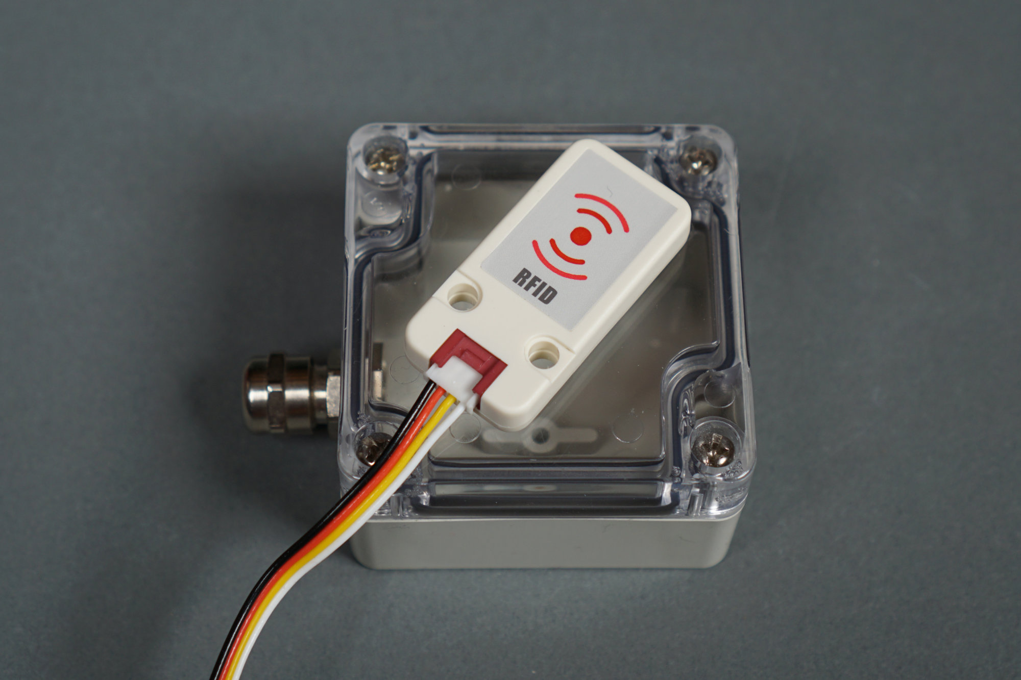
The M5Stack RFID reader is small enough to place in a waterproof enclosure and mount outside.
What I really like about the M5Stack RFID reader is that with only the M5Stack RFID reader, an M5Stack Atom Lite ESP32-pico based development kit, an M5Stack relay board and a SEEED Grove I2C hub board, you can build a complete RFID system that can control external gadgets for about $35 with zero soldering.
The reader is also small enough to fit in a small waterproof enclosure like the one from Hammond Manufacturing shown in the photo above. Ultimately, I decided against using the M5Stack RFID reader for my project though.
HID Global multiClass and iClass Readers
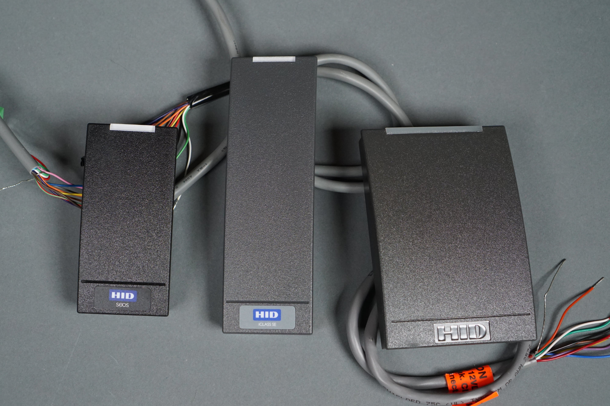
Various flavors of HID Global RFID proximity card readers.
Next up were various versions of the HID Global readers we’re all familiar with from badging into the office in the mornings. These seemed ideal for my application because they’re designed specifically for access control and they’re also designed to be mounted on the exteriors of buildings. What I didn’t know until I purchased a few to experiment with was exactly what type of cards they would or would not read.
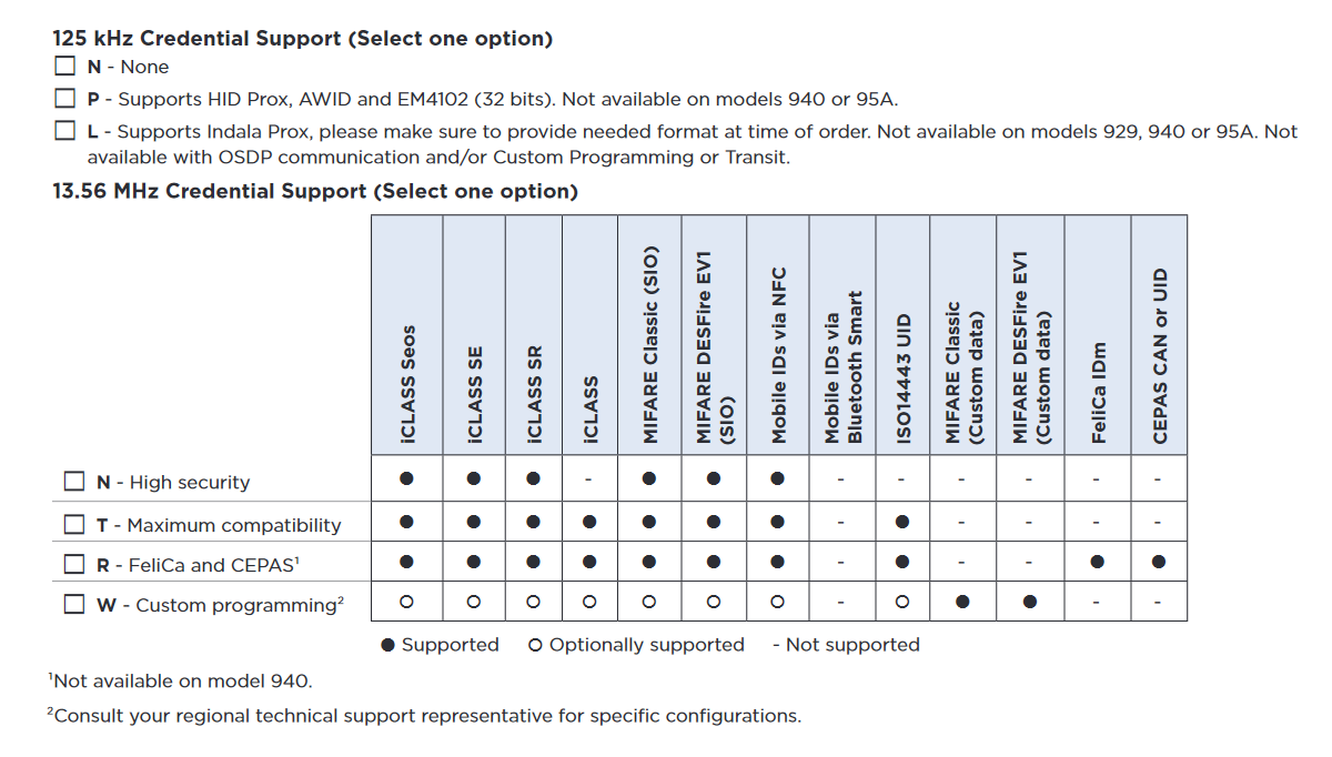
Credential support options from the HID reader configuration guide.
The table above from the HID reader configuration guide (PDF) shows the available credential support options when ordering a basic iClass SE reader. After reading the guide, I decided I wanted a reader that supported 125 kHz credentials and I wanted a reader that would support credentials with an ISO14443 UID like the sticker I chose for the back of my helmet.
SIO is a secure identity object that provides higher security when using MIFARE cards than just using the MIFARE card’s ISO14443 UID. With the right software, card writer, and licenses, it’s possible to embed an SIO in a generic MIFARE card. This seems rather complicated and likely not possible for a hobbyist.
I also decided I wanted a Standard v1 keyset reader with Wiegand output. I searched eBay for used readers with part numbers matching these four criteria and ordered a few to experiment with to make sure they’d read the sticker I chose for my helmet.
Wiegand Protocol
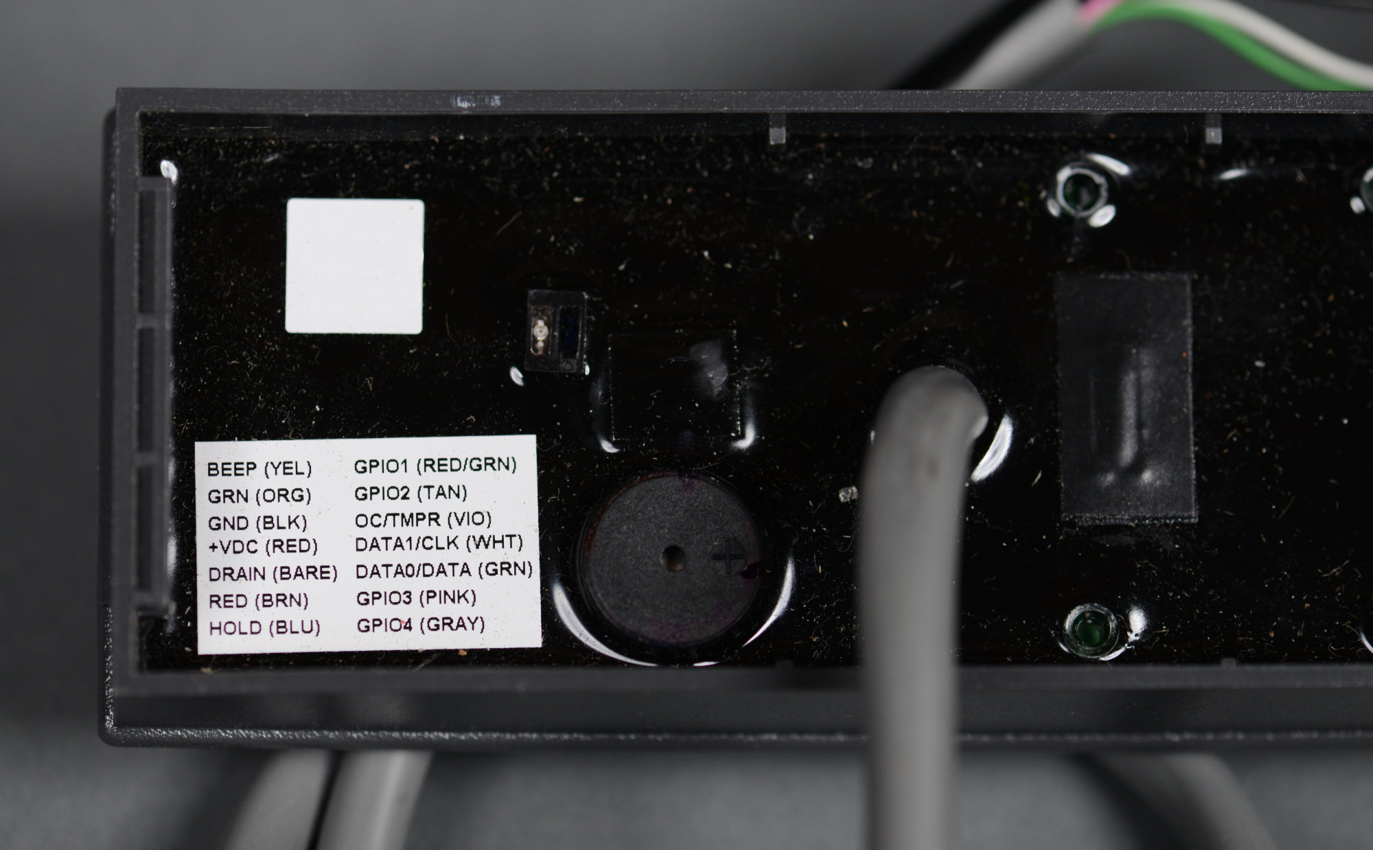
All the readers use the same color code. I’m only interested in the red, black, green, and white wires.
The reader I selected uses the Wiegand protocol for communicating with the rest of the access control system. The Wiegand protocol traces its history to early access control cards that used the Wiegand effect.
This protocol sends one bit at a time using a two wire interface. Both wires are normally high. For each bit sent, one of the two wires is pulled low. If the green wire is pulled low, the bit is a zero. If the white wire is pulled low, the bit is a one. Both wires return to high between bits. I had no idea of the timing of the bits or voltage of the interface though.
When one of the readers arrived, I connected it to a bench supply and an oscilloscope to observe the Wiegand protocol output from the reader. I needed to know the time between each bit, the duration of each bit, and the voltage used by the interface so that I could design hardware and software to receive and decode the card numbers sent from the reader.

Complete 32-bit ISO14443 UID from a HID Global reader. The yellow trace on top is connected to the green ‘0’ wire and the green trace on bottom is connected to the white ‘1’ wire.
The scope trace above shows the Wiegand output from the reader when a MIFARE classic card that was previously used as part of a hotel’s door lock system is presented to the reader. Looking at the voltage range of the traces, it’s clear that the Wiegand interface is a five volt interface. The 32 bits transmitted correspond to the cards ISO14443 UID, 9D:F2:11:78 (UID bytes are transmitted lowest byte first).
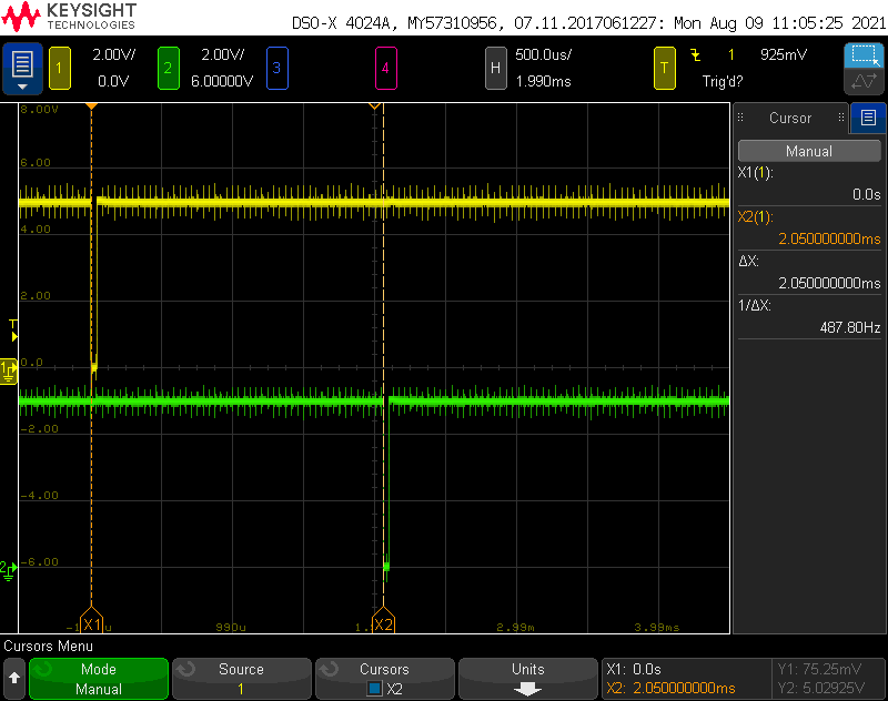
Time between bits from the same card and reader.
Next, the scope trace above shows the time between bits. I’m going to call it 2 milliseconds.
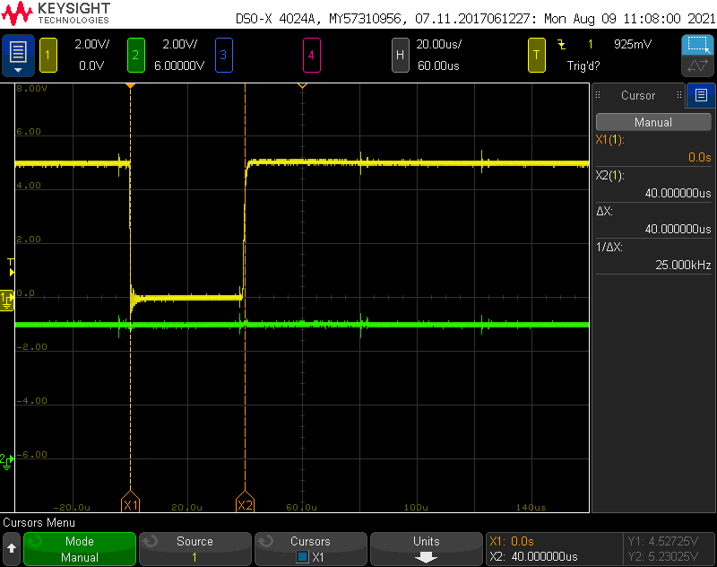
Time of a single bit from the same card and reader.
Finally, the scope trace above shows the duration of a single bit. It’s only 40 microseconds! It might be good to use an interrupt to detect the zero’s and one’s rather than trying to poll them from the software’s main loop. I measured several other cards. The number of bits transmitted varied based on the card type but the time between bits and the duration of each bit remained the same for all cards.
Design Requirements
With the measurement of the voltages and timing of the Wiegand protocol from the reader completed, I could begin designing the hardware and software for my simple access controller. The simple access controller will capture the UID from the card reader and make the decision to activate the garage door opener based on the received UID. The requirements:
- Two general purpose input pins preferably with interrupt capability for handling the Wiegand interface to the card reader. These lines must be protected against electrostatic discharge.
- The number of bits transmitted by the Wiegand protocol varies depending on the type of card presented and there’s no end of data signal so a timer must be available on the selected microcontroller to determine when the transmission of the card UID is complete.
- Use a simple 8-bit microcontroller. The microcontroller must run from 5 volts or have 5 volt tolerant inputs since 5 volts is the voltage of the Wiegand interface.
- At least two LEDs to indicate that the main loop of the software is running and to indicate if the UID received from the card reader is authorized or not.
- At least one relay to control the garage door opener when an authorized card is presented to the reader.
- The relay contacts must not activate the garage door opener at reset, at power up, at power down, or at anytime other than when an authorized card is presented to the reader.
- A few pushbutton switches might be useful but are not strictly necessary.
- Use an external 12 volt power input with an on-board 5 volt power supply for the selected microcontroller.
- Supply a 12 volt power passthrough for the card reader from the external supply.
- UID’s of authorized cards will be hardcoded and compiled into the software.
- All parts are either immediately available or I have them on-hand.
With the design requirements finalized, it was time to select components and start the schematic design.
Schematic Design
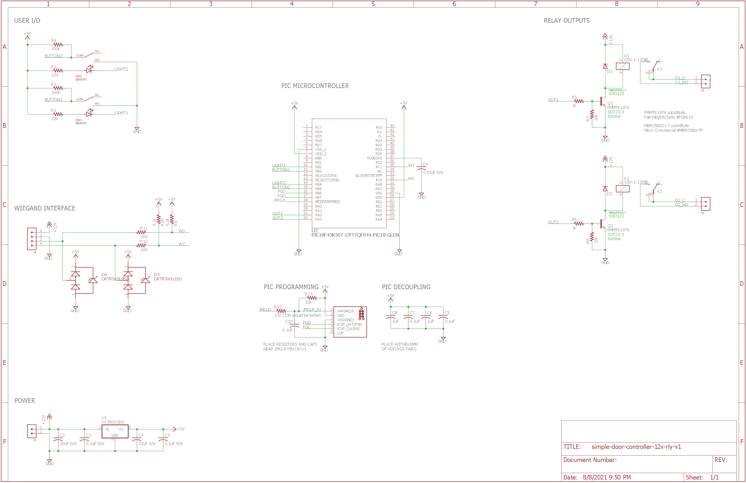
The final schematic for the simple door access controller.
As I started design of the schematic, my preference was for parts that I had on hand and parts that I had used before. The only parts I had trouble sourcing were the relays. I had to make a late design change to use relays with 12 volt coils instead of 5 volt coils because the 5 volt versions just weren’t available. Fortunately, I already planned to use a 12 volt power supply to power this project and therefore 12 volts was already available in the design.
Microcontroller
A small PIC microcontroller like a PIC18F1320 would be more than sufficient for this project. The PIC18F1320 has interrupt on change capability for a few of its pins when they’re configured as inputs and numerous timers so it meets the requirements for the project.
Unfortunately, the only PIC microcontroller I had ready access to due to the ongoing semiconductor shortage was a PIC18F45K50. It’s overkill for this application. Just like its smaller sibling, the PIC18F45K50 has interrupt on change capabilities and numerous timers. I will not be using its USB functionality for this project.
The PIC18F45K50 has an internal oscillator that is accurate enough for our application so an external crystal or oscillator is not needed. In addition to the usual 0.1 uF decoupling capacitors close to the VDD pins, the PIC18F45K50 requires a low-ESR 0.47 uF capacitor between its VUSB3V3 pin and ground. This is C9 in the schematic.
The data sheet also recommends 1 uF in parallel to each of the 0.1 uF capacitors if the PIC is located more than a few inches from its 5V power supply. Our is not so the 1 uF caps are not strictly necessary in this design.
Card Reader Wiegand Interface
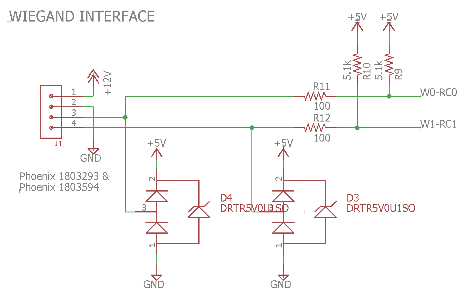
The Wiegand interface portion of the schematic.
The card reader connects to the simple access controller via a four position, 3.81 mm pitch Phoenix pluggable terminal block. Pin 1 is +12 volts to power the reader, pin 2 is ground, pin 3 connects to the reader’s green ‘0’ output and pin 4 connects to the reader’s white ‘1’ output. 12 volts from the external power supply is passed through from the power input connector the reader connector.
Pins 3 and 4 from the reader connector connect to the microcontroller’s RC0 and RC1 pins. RC0 and RC1 have interrupt on change capabilities when configured as inputs. D3 and D4 provide ESD protection and R11 and R12 limit current into the microcontroller during ESD events and short circuits and reduce reflections back to the reader. R9 and R10 are optional 5 volt pull-up resistors because some Wiegand readers do not have internal pull-up resistors. The reader I will be using does so R9 and R10 are not stuffed on the board.
Relays and Drivers
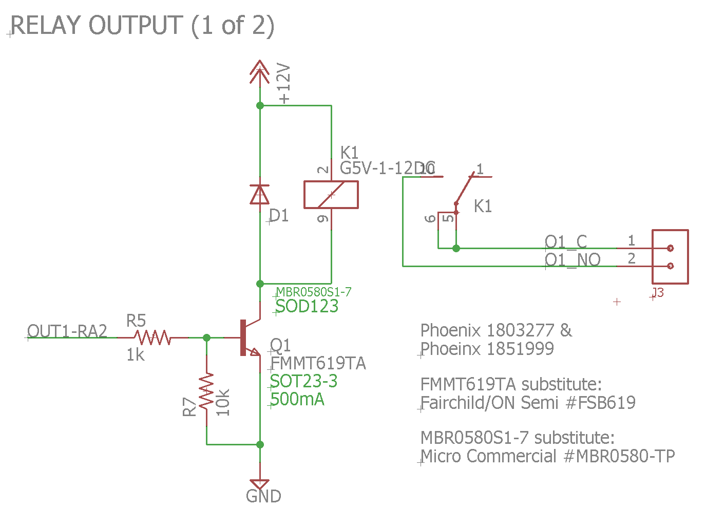
Schematic of the first of two of the relay outputs.
The 12 volt relay coils are switched using basic transistor switch circuits connected to the microcontroller’s RA2 and RA3 pins. R5 and R6 limit the current into the base of the transistors. R7 and R8 keep the transistors from turning on while the PIC microcontroller is in reset and during software initialization. Once the software is initialized, the micro drives the pins low to keep the relays from turning on.
When an authorized card is detected, the microcontroller drives RA2 high for about one half second. This turns on transistor Q1 and energizes relay K1’s coil. This in turn closes the relay’s contacts which then activate the garage door opener. Connections to the relays are made using a pair of 2 position, 3.81 mm pitch Phoenix pluggable terminal blocks. D1 and D2 protect the transistors from back EMF when the relays are switched off. Relay K2 is presently unused.
LEDs and Switches
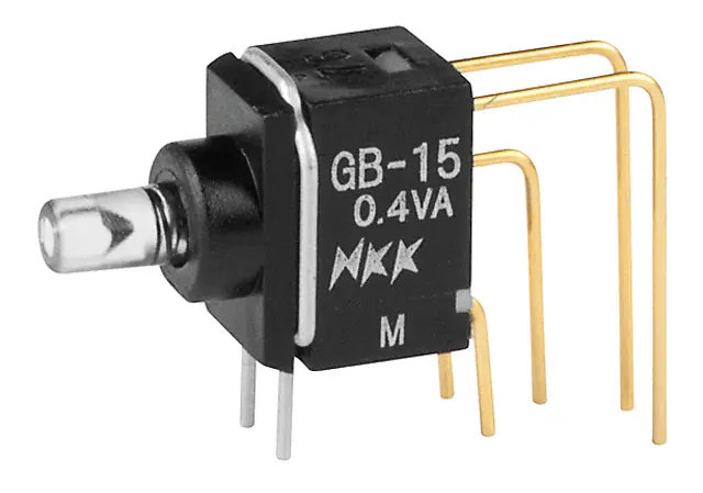
Photo of an NKK GB15JVC / GB15JVF switch from digikey.com.
For the pushbutton switches and LEDs, I’m using one red NKK GB15JVC switch and one green NKK GB15JVF switch. The stock photo of one of these switches from digikey.com is shown above. These switches have built in LED illumination and light pipes, look great, and don’t occupy much board or front panel space.
Power Supply

The 5V power supply for the microcontroller.
The simple access controller requires an external 12 volt power supply connected to a 2 position, 3.81 mm pitch Phoenix pluggable terminal block. An internal 5V DC/DC converter from CUI steps the 12 volts down to 5 volts to power the microcontroller. The 12V from the external power supply is made available on the reader connector to simplify and clean up the external wiring to the simple access controller.
Programming and Debugging
I’m using a Tag-Connect footprint with Microchip’s recommended debug circuit to program and debug the microcontroller.
Board Design
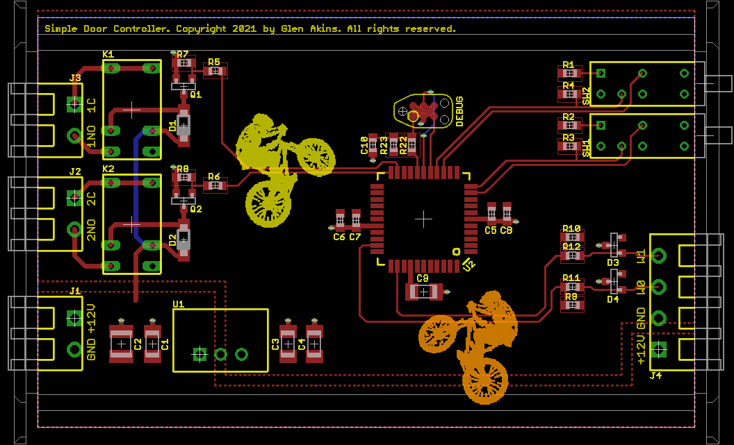
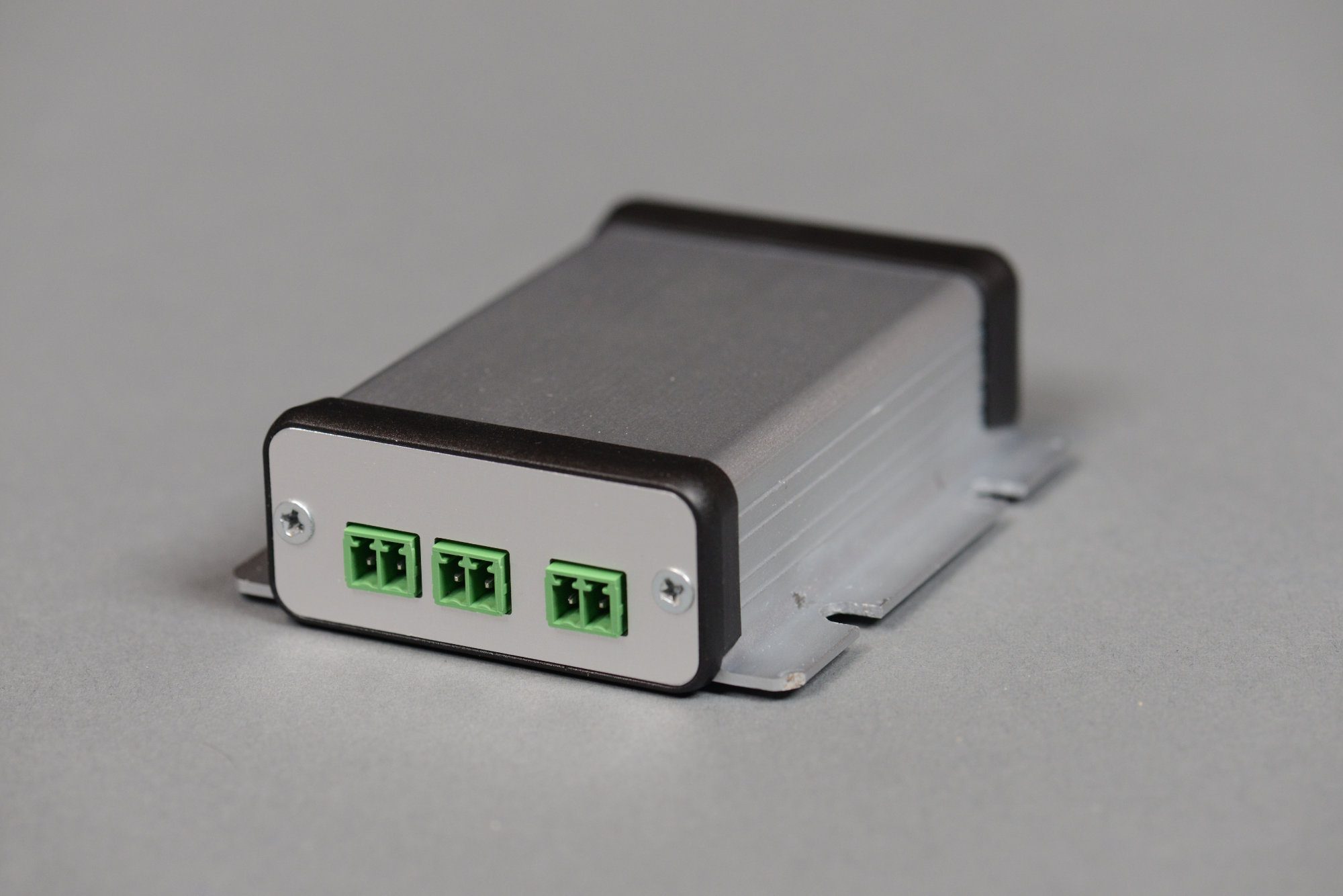
The completed board design.
The board is designed to fit in a Hammond 1455C801 extruded aluminum enclosure using the supplied black plastic bezels between the enclosure and end panels. If using the flanged 1455CF801 version of the enclosure, the connectors and switches need to be moved inward by 1.4 mm on each end of the board or a set of bezels needs to be modified to fit on the flanged enclosure.
Guides on the documentation layers indicate where the board slides into the card guides on the chassis. No components or vias are allowed in this region. A second set of guides indicate where the board intersects with the enclosure’s screw holes as it’s slid into the chassis. No tall components are allowed inside this region. On either end of the board design are a final set of guides that show where the end panels on the enclosure intersect with the components that extend past the edges of the board.
The power and relay connectors are on one end of the board. The switches and reader connector are on the other end of the board. There’s lots of space left on the board for other components if needed for future design iterations.
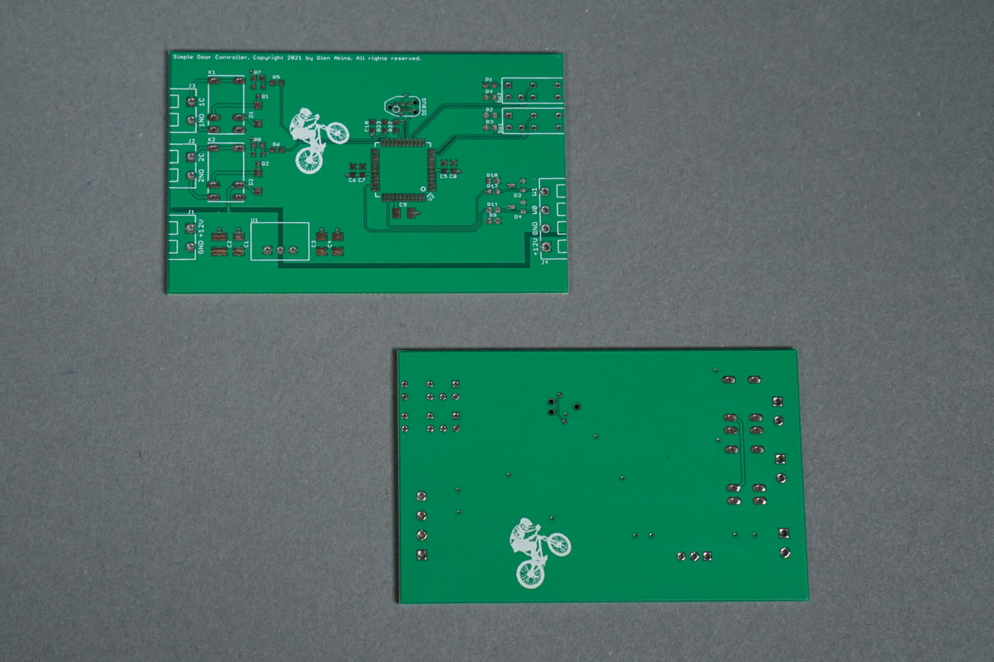
The front and back of the fabricated boards.
The photo above shows the fabricated boards.
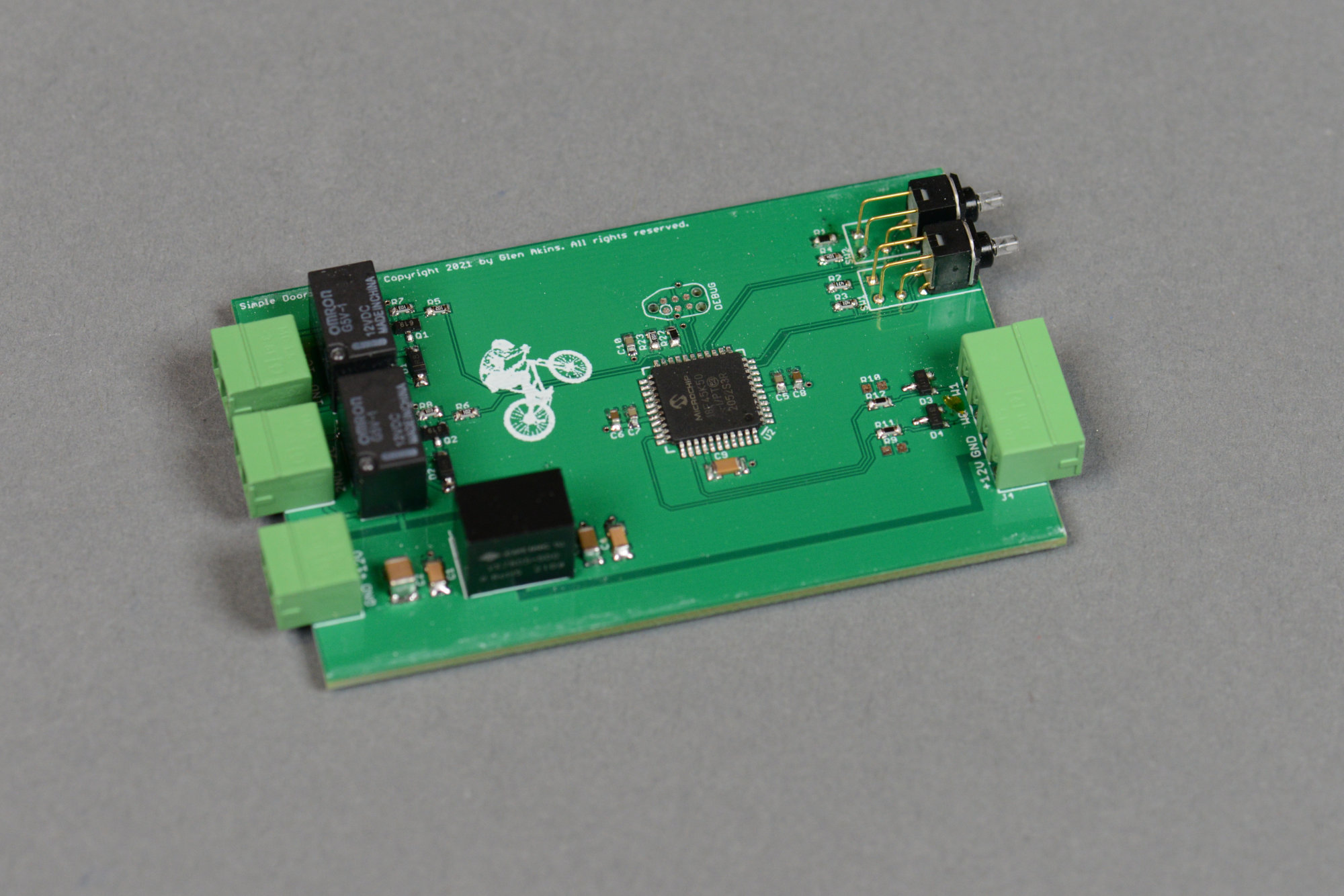
The assembled board.
The photo above shows an assembled board.
Enclosure Design

The completed enclosure design.
I designed the end panels for the enclosure using Front Panel Express’s design software. After the panels were designed, I exported the board and panels to Fusion 360 to verify their fit. Once I was happy with how everything fit together, I ordered the panels from Front Panel Express.
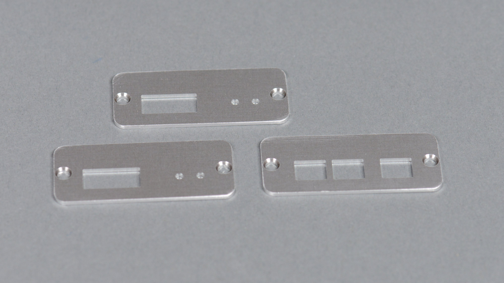
The fabricated end panels.
The photo above shows the fabricated end panels.
Software
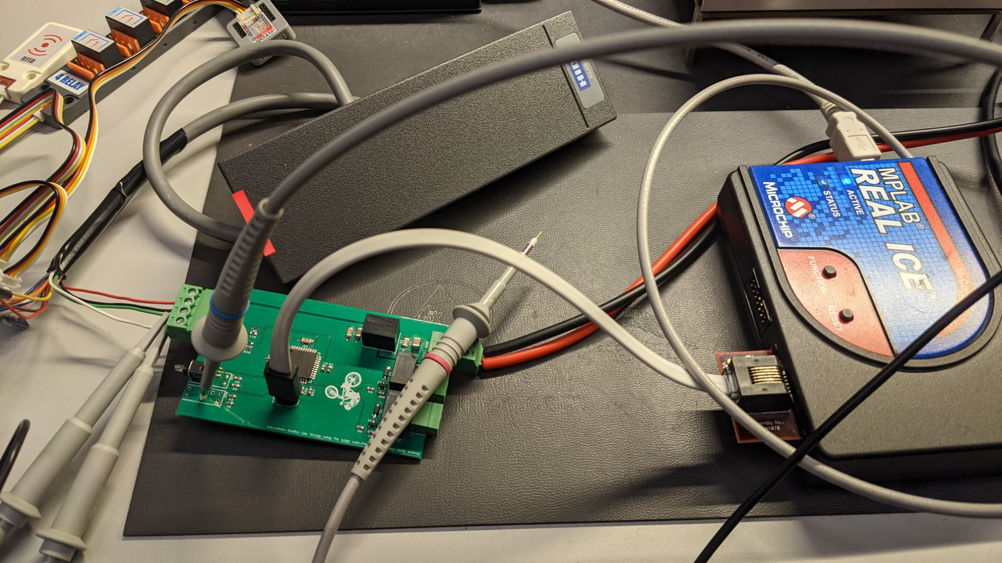
The debug setup for testing the hardware and writing the software for the simple access controller.
After assembling the board, it was time to start on the software. I wrote the software in three phases. The first phase was getting a timed main loop running that would blink a heartbeat LED periodically. The second phase was writing the interrupt driven code to receive and decode the Wiegand protocol. The third phase was comparing the received Wiegand data to a list of authorized cards and turning on the red LED if the card was not authorized and turning on the green LED and first relay if the card was authorized.
Main loop and Heartbeat LED
One of the first steps to bringing up just about any board is to get an LED blinking. This proves the debugger can talk to the microcontroller and that the oscillator and microcontroller are running. I like to blink the LED from the main loop and use a timer interrupt to control the rate of the main loop execution. This shows me that the main loop executes, interrupts work, and, by comparing the actual LED period to the expected LED period, I can ensure the oscillator is running at the correct frequency.
My code usually looks a bit like this early in the bring up phase:
...

// 250 Hz timer 2 period value
// dec2hex(12e6/16/12/250-1)
#define TMR2_PERIOD 0xF9

// led states
#define LED_ON   0
#define LED_OFF  1

volatile uint8_t flag250 = 0;

void main(void)
{
    // set up clocks and oscillators
    SYSTEM_Initialize ();

    // no analog I/O
    ANSELB = 0;

    // initialize LEDs to off
    LATBbits.LATB2 = LED_OFF;
    LATBbits.LATB4 = LED_OFF;
    TRISBbits.TRISB2 = 0;
    TRISBbits.TRISB4 = 0;

    // enable priority interrupts
    RCONbits.IPEN = 1;

    // configure TMR2
    TMR2_Initialize ();

    // enable interrupts
    INTCONbits.GIEH = 1;
    INTCONbits.GIEL = 1;

    while(1)
    {
        // run 250 Hz tasks
        if (flag250) {
            // clear flag
            flag250 = 0;

            // blink led or turn on for a while if not authorized
            if (ledTimer == 0) {
                LED1 = LED_ON;
            } else if (ledTimer == 25) {
                LED1 = LED_OFF;
            }

            // increment led timer counter, 1.0 second period
            if (++ledTimer >= 250) {
                ledTimer = 0;
            }
        }
    } //end while
} //end main


void TMR2_Initialize (void)
{
    PR2 = TMR2_PERIOD;
    TMR2 = 0x00;
    IPR1bits.TMR2IP = 0;
    PIR1bits.TMR2IF = 0;
    PIE1bits.TMR2IE = 1;
    T2CON = 0x5E;
}


void __interrupt(low_priority) SYS_InterruptLow(void)
{
    if (PIE1bits.TMR2IE == 1 && PIR1bits.TMR2IF == 1)
    {
        TMR2_InterruptHandler();
    }
}


void TMR2_InterruptHandler (void)
{
    PIR1bits.TMR2IF = 0;
    flag250 = 1;
}

...
This code initializes the GPIO for the LED, turns the LED off, initializes a timer to generate an interrupt every 4 ms, then waits for flag250 to be set by the timer interrupt service routine. Once the flag is set, the main loop uses a the led_timer counter to turn on the led for 100 ms every second. Blink, blink!
Decoding Wiegand Using the Interrupt on Change Pins and a Timer Interrupt
Scope traces while decoding Wiegand protocol. Yellow is a ‘0’, green is a ‘1’, blue is the decoded data, magenta is the timer expiring signalling the end of the data.
The next step in the project was to write the software to receive and decode the Wiegand data from the card reader. I’m using the PIC18’s interrupt on change feature and timer 0 to receive and decode the Wiegand data inside a few interrupt service routines. Once the complete card ID is received from the reader, the ISR sets a flag and gives the main loop a copy of the card ID to check.
The first step was to allocate some global variables for use by the interrupt service routines. The first four variables are used exclusively by the ISRs. The last two variables are used to pass the received card ID from the ISR to the main loop for checking against the list of authorized card IDs.
// work variables for constructing card UID from card reader
uint8_t cbits = 0;
uint8_t newUidBit = 0;
uint8_t uidBits = 0;
uint8_t uidData[8];
uint8_t mainUidBits = 0;
uint8_t mainUidData[8];
The next step was to add code inside main to initialize RC0 and RC1 as inputs and enable the interrupt on change interrupts on these two inputs:
    // no analog I/O
    ANSELC = 0;

    // initialize W0, W1 as inputs
    TRISCbits.TRISC0 = 1;
    TRISCbits.TRISC1 = 1;

    // clear uid from card
    uidBits = 0;
    for (i = 0; i < 8; i++) {
        uidData[i] = 0;
    }

    // enable iocc0 and iocc1
    IOCCbits.IOCC0 = 1;    // enable IOCC0
    IOCCbits.IOCC1 = 1;    // enable IOCC1
    cbits = PORTC;         // latch state
    INTCON2bits.IOCIP = 0; // low priority
    INTCONbits.IOCIF = 0;  // clear flag
    INTCONbits.IOCIE = 1;  // enable interrupt
Then I needed to add some code to the low priority interrupt interrupt handler to dispatch to the IOC and TMR0 interrupt handlers based on the state of the interrupt enable and interrupt flag bits:
    if (INTCONbits.IOCIE == 1 && INTCONbits.IOCIF == 1) {
        IOC_InterruptHandler();
    }

    if (INTCONbits.TMR0IE == 1 && INTCONbits.TMR0IF == 1) {
        TMR0_InterruptHandler();
    }
Things start to get interesting inside the IOC interrupt handler. When an IOC interrupt occurs, the code reads PORTC and checks the state of the lower two bits. If RC1 and RC0 are both low, something is wrong because both lines should never be low in the Wiegand protocol. If they are low, we reset the UID receive routine and start over. If RC1 and RC0 are both high, that’s just the Wiegand protocol returning to the idle state between bits and we can safely ignore it. If only RC1 is low (it’s connected to the white ‘1’ wire), we shift in a ‘1’ bit into the current UID. If only RC0 is low (it’s connected to the green ‘0’ wire), we shift in a ‘0’ bit into the current UID. Finally, we clear the IOC interrupt flag bit.
void IOC_InterruptHandler (void)
{
    cbits = PORTC;

    switch (cbits & 3) {
        case 0:
            // both low is an error, reset the UID and start over
            ResetUID ();
            break;
        case 1:
            // W1 is low and W0 is high, that's a '1'
            newUidBit = 1;
            ShiftUID ();
            break;
        case 2:
            // W1 is high and W0 is low, that's a '0'
            newUidBit = 0;
            ShiftUID ();
            break;
        case 3:
            // both high is a no operation
            break;
    }

    INTCONbits.IOCIF = 0;  // clear flag
}
The UID reset routine sets the number of received bits to zero and clears the received UID.
void ResetUID (void)
{
    uint8_t i;

    uidBits = 0;
    for (i = 0; i < 8; i++) {
        uidData[i] = 0;
    }
}
The shift routine increments the count of bits received and shifts the new UID bit into the 8 byte array holding the current UID. If the number of bits received exceeds 64, it clears the bit count, clears the UID, and starts over. After any bit is shifted in, the shift routine sets timer 0 to timeout at 4 ms. Since bits are received every 2 ms, the timeout timer will be restarted before timing out after every bit except for the last bit. After the last bit is received, the timer will time out after 4 ms and generate an interrupt.
void ShiftUID (void)
{
    if (uidBits >= 64) {
        ResetUID ();
    } else {
        uidBits++;

        uidData[7] = uidData[7] << 1;
        uidData[7] |= (uidData[6] & 0x80) ? 1 : 0;

        uidData[6] = uidData[6] << 1;
        uidData[6] |= (uidData[5] & 0x80) ? 1 : 0;

        uidData[5] = uidData[5] << 1;
        uidData[5] |= (uidData[4] & 0x80) ? 1 : 0;

        uidData[4] = uidData[4] << 1;
        uidData[4] |= (uidData[3] & 0x80) ? 1 : 0;

        uidData[3] = uidData[3] << 1;
        uidData[3] |= (uidData[2] & 0x80) ? 1 : 0;

        uidData[2] = uidData[2] << 1;
        uidData[2] |= (uidData[1] & 0x80) ? 1 : 0;

        uidData[1] = uidData[1] << 1;
        uidData[1] |= (uidData[0] & 0x80) ? 1 : 0;

        uidData[0] = uidData[0] << 1;
        uidData[0] |= newUidBit ? 1 : 0;
    }

    // set data timeout timer to 4 milliseconds
    TMR0_Initialize ();
}
Here’s the code to reset timer 0 to 4 ms and enable it and its interrupt if they’re not already enabled:
// 4 ms timer 0 load / reload value
// dec2hex(65535-12e6/16/250) = 0xF447
#define TMR0_RELOAD_VALUE 0xF447

void TMR0_Initialize (void)
{
    T0CONbits.T08BIT = 0;
    TMR0H = TMR0_RELOAD_VALUE >> 8;
    TMR0L = TMR0_RELOAD_VALUE & 0xFF;
    INTCON2bits.TMR0IP = 0;
    INTCONbits.TMR0IF = 0;
    INTCONbits.TMR0IE = 1;
    T0CON = 0x93;
}
Finally, here’s the timer 0 interrupt handler. It clears the interrupt flag, disables the interrupt, disables the timer, and copies the received number of bits and the received UID into a second set of variables that are accessed by the main loop:
void TMR0_InterruptHandler (void)
{
    uint8_t i;

    // clear flag, disable interrupt, and stop timer
    INTCONbits.TMR0IF = 0;
    INTCONbits.TMR0IE = 0;
    T0CONbits.TMR0ON = 0;

    if (uidBits >= 26) {
        // forward UID to main loop for checking
        mainUidBits = uidBits;
        for (i = 0; i < 8; i++) {
            mainUidData[i] = uidData[i];
        }
    }

    // get ready for next card scan
    ResetUID ();
}
I’m not worried about race conditions between the ISR and the main loop code. When connected to a legitimate reader, the ISR code will take a minimum of 56 ms (2*26 for bits + 4 for timeout) to receive a UID. The main loop will always be done processing its copy of the UID within 4 ms.
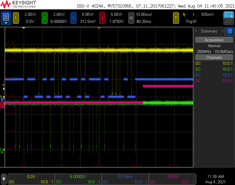
Scope traces while decoding Wiegand protocol. Yellow is a ‘0’, green is a ‘1’, blue is the decoded data, magenta is the timer expiring signalling the end of the data.
To debug the Wiegand receive routine, I used a four channel scope connected to the two Wiegand data lines and two unused output pins on the PIC. A screen capture from the scope after receiving a 32 bit UID from the reader is shown in the image above.
- Channel 1 is the yellow trace and was connected to the Wiegand ‘0’ signal.
- Channel 2 is the green trace and was connected to the Wiegand ‘1’ signal.
- Channel 3 is the blue trace. This trace was connected to the first unused output pin. It was set to a zero or a one based on the value of newUidBit inside ShiftUID. This allowed me to see when the IOC interrupt occurred and that the ShiftUID routine was shifting the correct bit value into the UID array.
- Channel 4 is the magenta trace. This trace was connected to the second unused output pin. It was set high inside the timer 0 interrupt handler routine after the 4 ms timeout occured. This allowed me to verify the timeout was only occurring after the end of the UID data and it was happening in a timely fashion after the end of the UID data.
Checking Card Authorization and Controlling the LEDs and Relays
The next step was to compare the received UID against a list of authorized UID’s compiled into the software. I defined a value with the number of authorized UID’s then added an array with 8 bytes for each authorized UID. I initialized the array with the UID’s of a sticker on my bike helmet and another sticker on my skateboard helmet. Both of these UID’s are only 32 bits.
#define N_CARDS 2

const uint8_t authedUids[N_CARDS][8] = {
    { 0x12, 0x34, 0x56, 0x78, 0x00, 0x00, 0x00, 0x00 }, // bike helmet
    { 0x12, 0x34, 0x56, 0x79, 0x00, 0x00, 0x00, 0x00 }  // skate helmet
};
I added some code to the main loop that is executed every 4 ms. When the ISR sets the main loop’s copy of the received number of UID bits to a non-zero value, the code executes and looks for a match. If a match is found, the UID is authorized and the code:
- turns on the green LED
- sets a timer to turn off the green LED after 1 second
- turns on relay 1
- sets a timer to turn off relay 1 after 1 second.
If a match is not found, the UID is not authorized and the code:
- turns on the red LED
- sets a timer to turn off the red LED after 1 second
- the relay remains off.
After checking for a match, the code clears its copy of the number of UID bits to zero so that it does not execute again until the next card number is received.
            if (mainUidBits != 0) {
                // check card against valid cards
                notAuthorized = 1;
                for (card = 0; card < N_CARDS; card++) {
                    uidAuthorized = 1;
                    for (i = 0; i < 8; i++) {
                        if (mainUidData[i] != authedUids[card][i]) {
                            uidAuthorized = 0;
                        }
                    }
                    if (uidAuthorized) {
                        notAuthorized = 0;
                        RELAY1 = RELAY_ON;
                        LED2 = LED_ON;
                        relayTimer1 = 125;
                        goodUidTimer = 250;
                    }
                }
                mainUidBits = 0;
                if (notAuthorized) {
                    badUidTimer = 250;
                }
            }
Finally here’s the code to control the red LED, the code to turn off the green LED after 1 second, and the code to turn off relay 0 after 0.5 seconds. The red LED normally blinks once per second except when an unauthorized card is presented in which case it lights steady for 1 second.
            // blink led or turn on for a while if not authorized
            if (badUidTimer != 0) {
                LED1 = LED_ON;
                badUidTimer--;
            } else if (ledTimer == 0) {
                LED1 = LED_ON;
            } else if (ledTimer == 25) {
                LED1 = LED_OFF;
            }

            // turn on green led for a while if authorized
            if (goodUidTimer != 0) {
                LED2 = LED_ON;
                goodUidTimer--;
            } else {
                LED2 = LED_OFF;
            }

            // decrement relay 1 timer until it hits zero then turn off the relay
            if (relayTimer1 == 0) {
                RELAY1 = RELAY_OFF;
            } else {
                relayTimer1--;
            }
Assembly and Installation
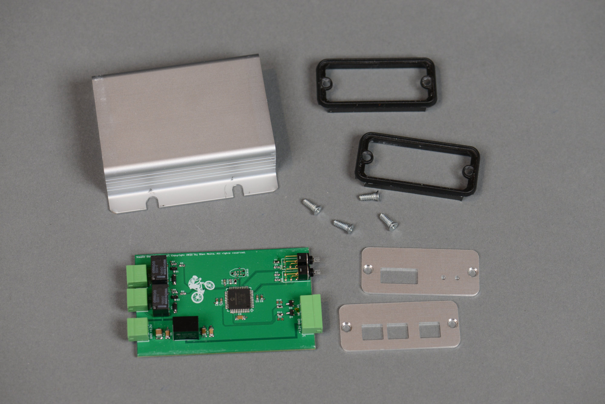
All the part required to assembled the simple access controller.
With all the parts and pieces in house and the software finished, it was time to assemble the project. The big question is if the cut outs on the panels would align perfectly with the components on the circuit board.
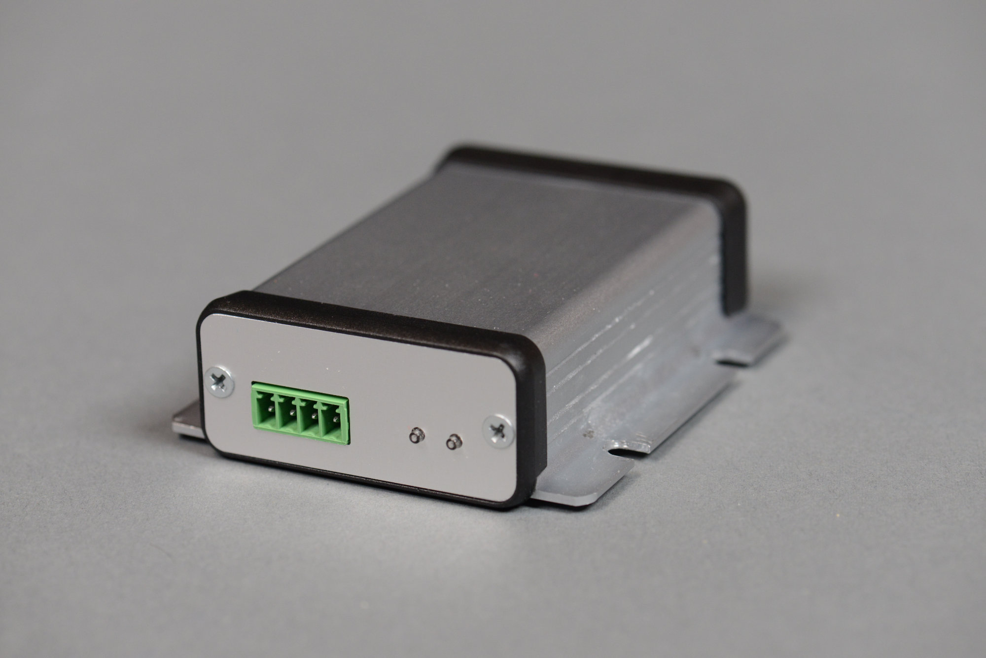
The reader side of the assembled project.
Tah-dah! The cut outs for the Phoenix connectors are maybe a bit high but the cut outs for the small circular illuminated pushbuttons are perfect. I could probably bend the connectors up a bit too but everything is close enough.
The power and relay side of the assembled project.
The other end of the project. The connectors are for relay 1, relay 2, and power.
Connecting to a Garage Door Opener Remote

The wireless garage door opener with a set of wires soldered across the pushbutton.
I had two options for connecting to the garage door opener and controlling the garage door. The first would be to run a cable between the door opener and the simple access controller. The second would be to hack a door opener remote to allow it to be controlled by an external relay. I went with the latter. I’m out of cable staples and I was trying to minimize the amount of time spent on a latter in the garage.
I took apart the opener and tacked two bodge wires in parallel with the pushbutton switch inside the opener. I routed those wires outside the opener then connected them to a larger gauge and more robust wire. Once I confirmed the hack worked, I taped the whole thing up with black electrical tape to keep the wires from coming loose or breaking. The larger gauge wire is connected to a Phoenix pluggable screw terminal block that is plugged into the relay 1 connector on the simple access controller.
Mounting Everything in the Garage
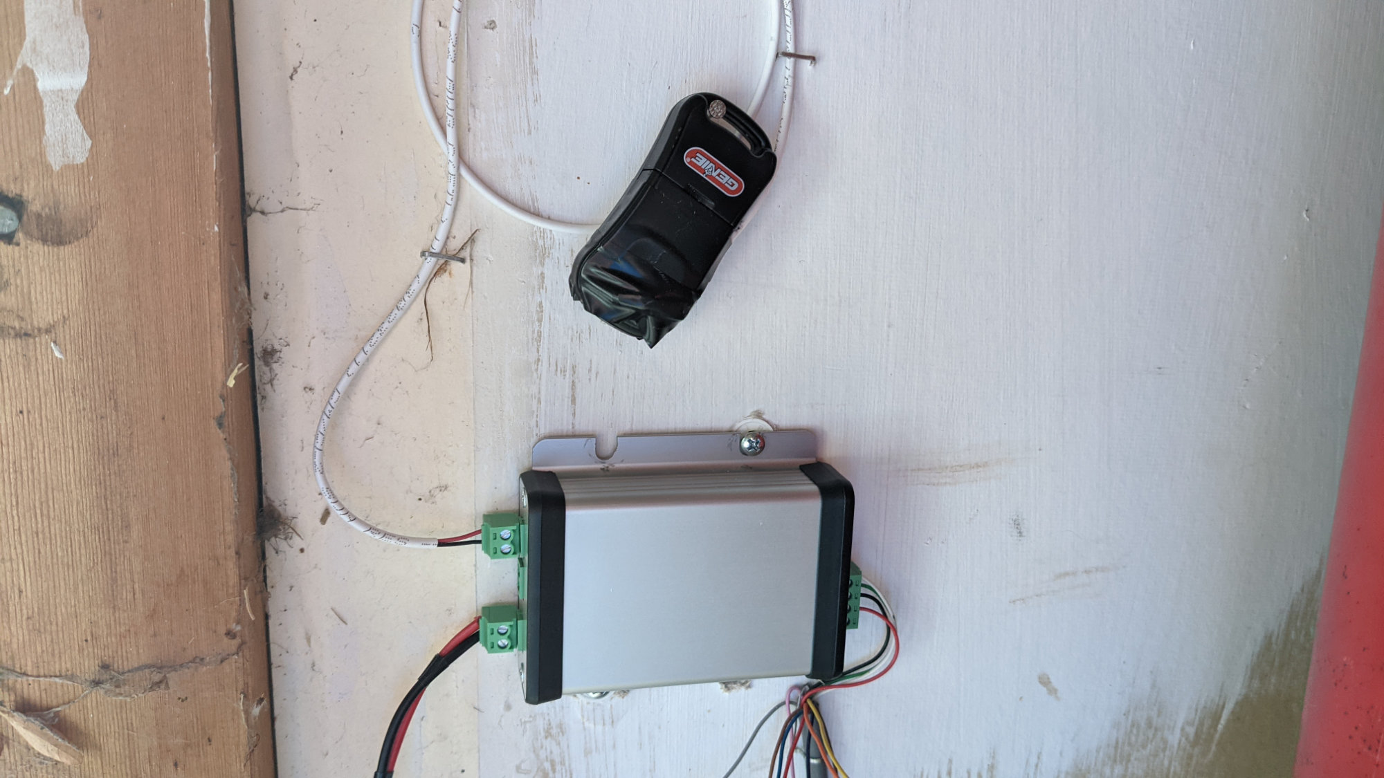
The assembled project installed inside the garage.
With everything tested, I mounted the garage door opener remote and the simple access controller to the wall just inside the garage and connected it to the HID Global card reader I previously mounted on the exterior of the house.
If you watch the video at the top of this post, you can see where I mounted the reader. I do not recommend mounting a reader in this location because it takes quite a bit of work to snake the reader’s pigtail through the headers around the garage door. In the case of my house, it was go through the headers or go through the brick. For better or worse, I went through the headers.
Security
Garage doors with openers are inherently insecure. They have both electronic and mechanical weaknesses. The rolling code remote control systems have long been hacked. Thieves know to reach in with a hanger and pull the emergency door release lever. The 24 to 37 bits of entropy provided by the typical RFID access control card is pretty good in comparison as long as you can prevent the card from being cloned. Newer RFID access control cards and readers address the eavesdropping and cloning issues with the older systems.
In the future, I could upgrade my system to use HID Global’s iClass SEOS cards and readers. This would prevent eavesdropping and cloning attacks but I’d have to trade the RFID sticker on the back of my helmet for a SEOS card or keyfob stuffed in my pack. If I wanted to stick with the cool helmet sticker, I’d have to implement my own authentication scheme with a PN532 reader and DESFire sticker which actually sounds like a pretty good future project. Speaking of which…
Future Upgrades
In the future, I might upgrade the reader and card to higher security devices. I’d also like to add some networking capabilities—either Ethernet with PoE or Wi-Fi. If the device were placed on the network, MQTT could be used to report scanned cards (both rejected and acceepted) to a logging system. A web browser interface could be used to enroll and delete authorized cards from memory. Finally, it’d be useful to have inputs to sense and report over MQTT when the door was closed, when the door was fully open, and when the door was somewhere between the two states.
Final Word
The goal with this project was to build something cool and useful and keep it as simple as possible. Achievement unlocked!

Design Files
The design files for this project are on Github.