
Philip Color Kinetics ColorBurst 4 10 watt RGB LED flood light controlled and powered over the network.
Time for another PoE project! This project uses a Silvertel 802.3at Ag5300 PoE+ module with a built-in isolated 24 V DC/DC converter to power a 10 W ColorKinetics ColorBurst 4 RGB LED floodlight. The Ethernet cable and light plug into a small power / control board and PoE+ powers the floodlight and Art-Net UDP packets control the light. If this were a real product, the power / control board would be integrated into the fixture and the Ethernet cable would then plug directly into the back of the light.
The Silvertel Ag5300 PoE+ Module
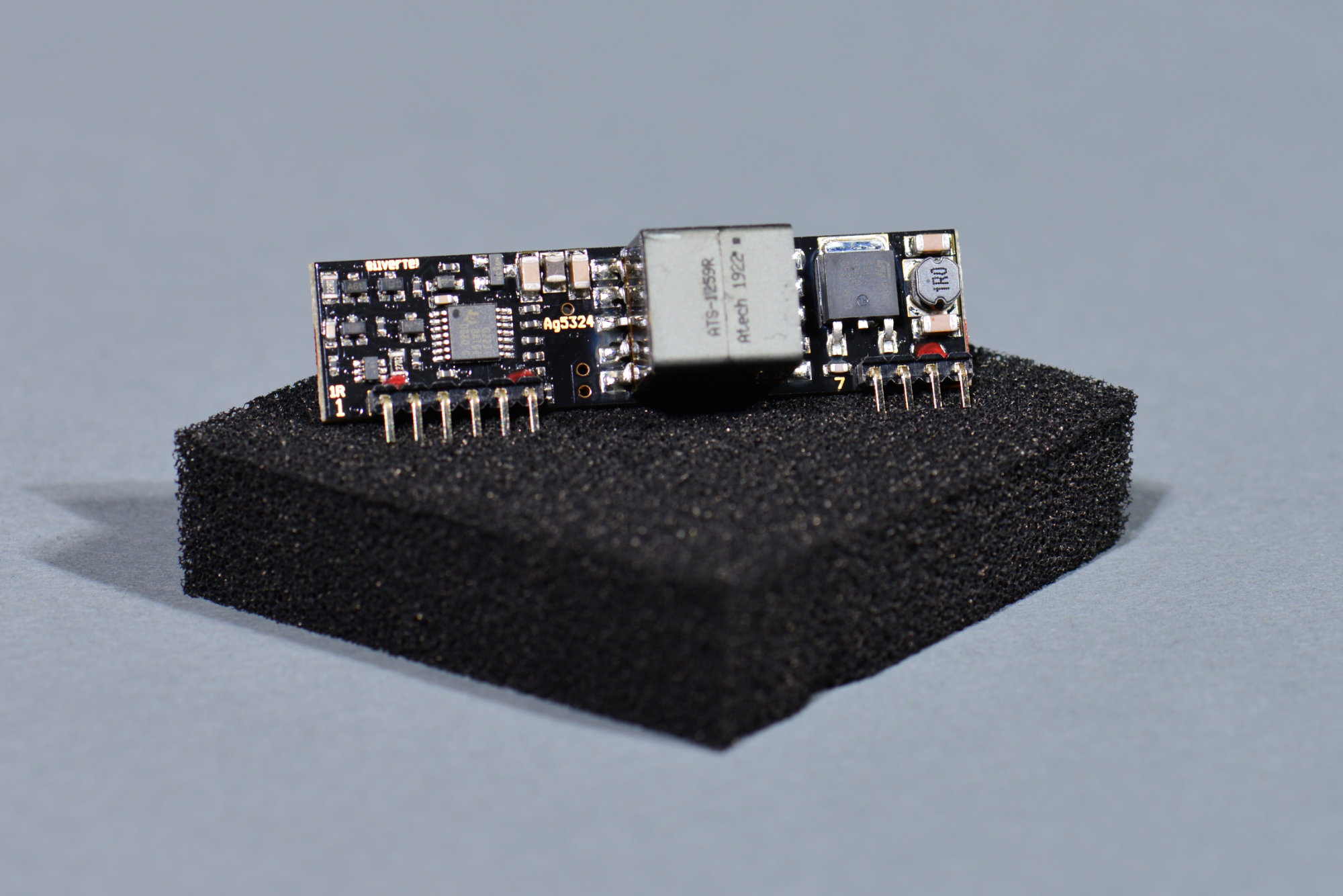
Silvertel Ag5324 PoE PD module with integrated isolated 24 V DC/DC converter.
My previous PoE projects here and here used a discrete Texas Instruments TPS2378 PoE+ classification IC and a Molex Ethernet jack with integrated magnetics and PoE+ classification circuitry. The TI TPS2378 is the lowest cost solution. The downside is it requires quite a other components to operate. The Molex jack is the highest cost solution but requires very few external components to operate.
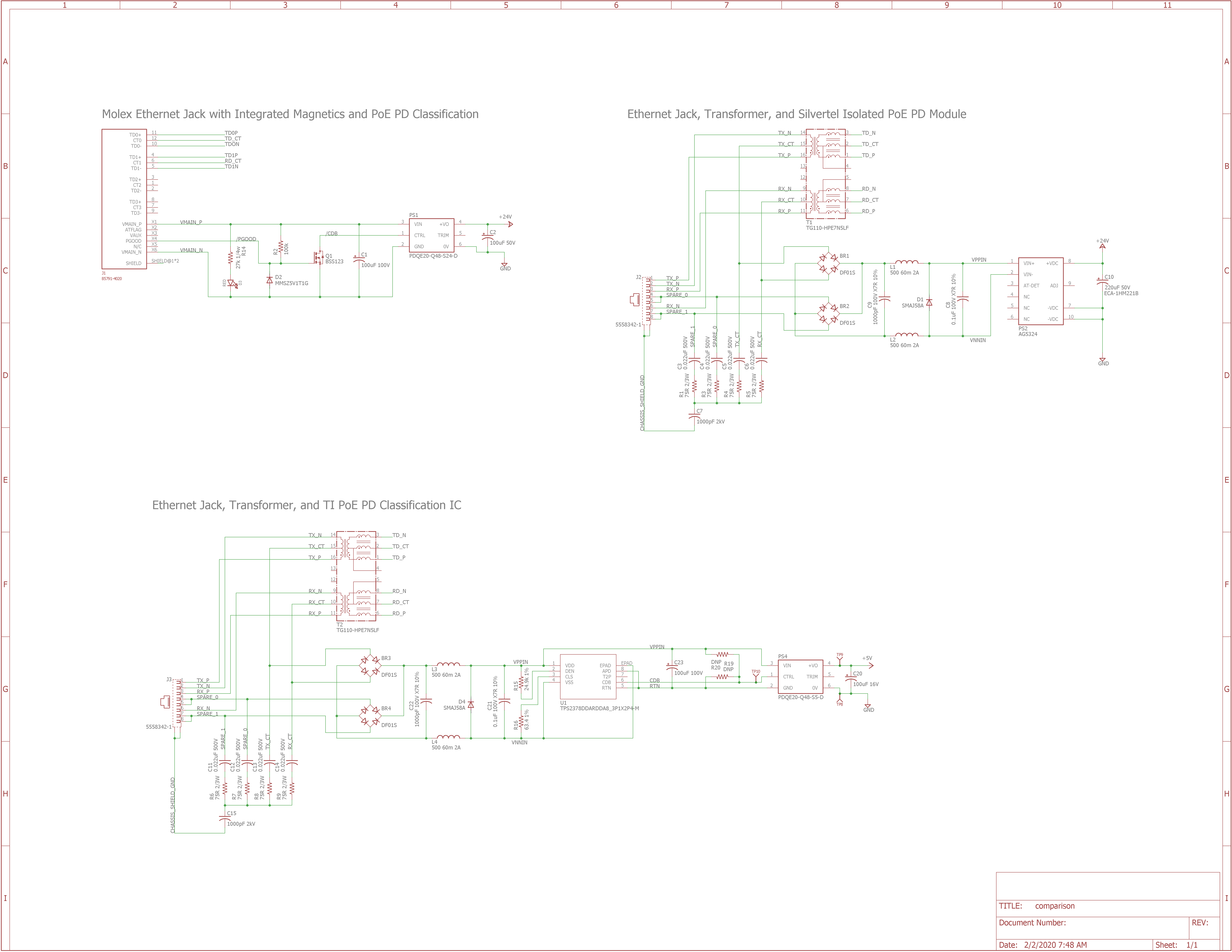
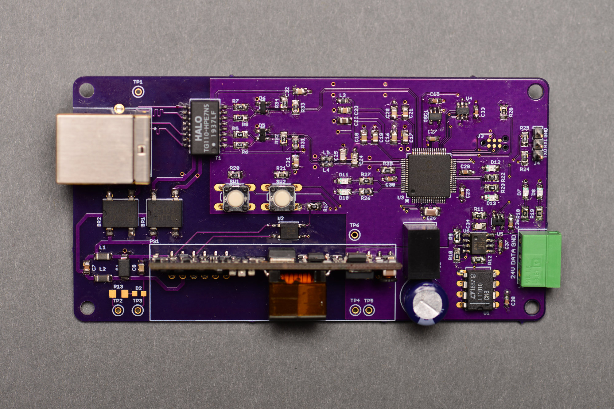
Three different isolated PoE PD designs. The top left design uses a Molex Ethernet jack with integrated magnetics and PoE PD classification circuitry. The bottom design uses an Ethernet jack, separate magnetics, and a TI PoE PD classification IC. The top right design, which is the design used in this project, uses an Ethernet jack, separate magnetics, and a Silvertel PoE module. The Silvertel module lies somewhere in the middle in terms of complexity. In the two more complicated designs, the transformer and Bob Smith termination network could be replaced with an Ethernet jack with integrated magnetics.
The Silvertel module sits somewhere in the middle of these other two solutions. It still requires a jack, magnetics, two bridge rectifiers, and a transient suppressor like the discrete TI solution, but, unlike the TI and Molex solutions, it includes an isolated 12 V or 24 V DC/DC converter. The integrated DC/DC converter can be a big cost savings and help to reduce the overall parts count.
The Plan
I have a box of Color Kinetics ColorBurst 4 lights sitting in my basement. These lights run from 24 volts, draw a maximum of 10 watts, and use a funky 24 volt version of the DMX-512 protocol. I tore down a larger ColorBurst 6 fixture a few years ago which is very similar in design and operation to the ColorBurst 4.
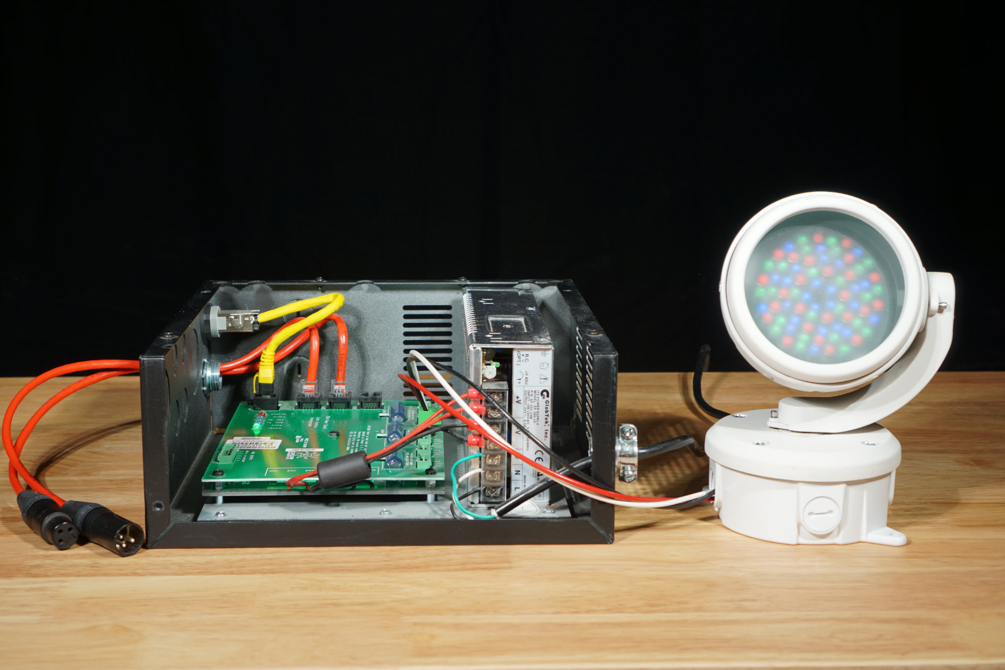
A Color Kinetics PDS-150e power data supply next to a single ColorBurst 4 fixture.
These lights are normally powered and controlled using a Color Kinetics power data supply like the PDS-150e shown in the photograph above. The PDS-150e contains a 24 volt, 150 watt DC power supply powered from the AC mains and a microprocessor that can control the lights using a Color Kinetics proprietary Ethernet-based protocol or DMX-512. This power data supply can power and control up to 12 ColorBurst 4 lights.
With enough of these fixtures in a row, they’re almost like giant Neopixels!
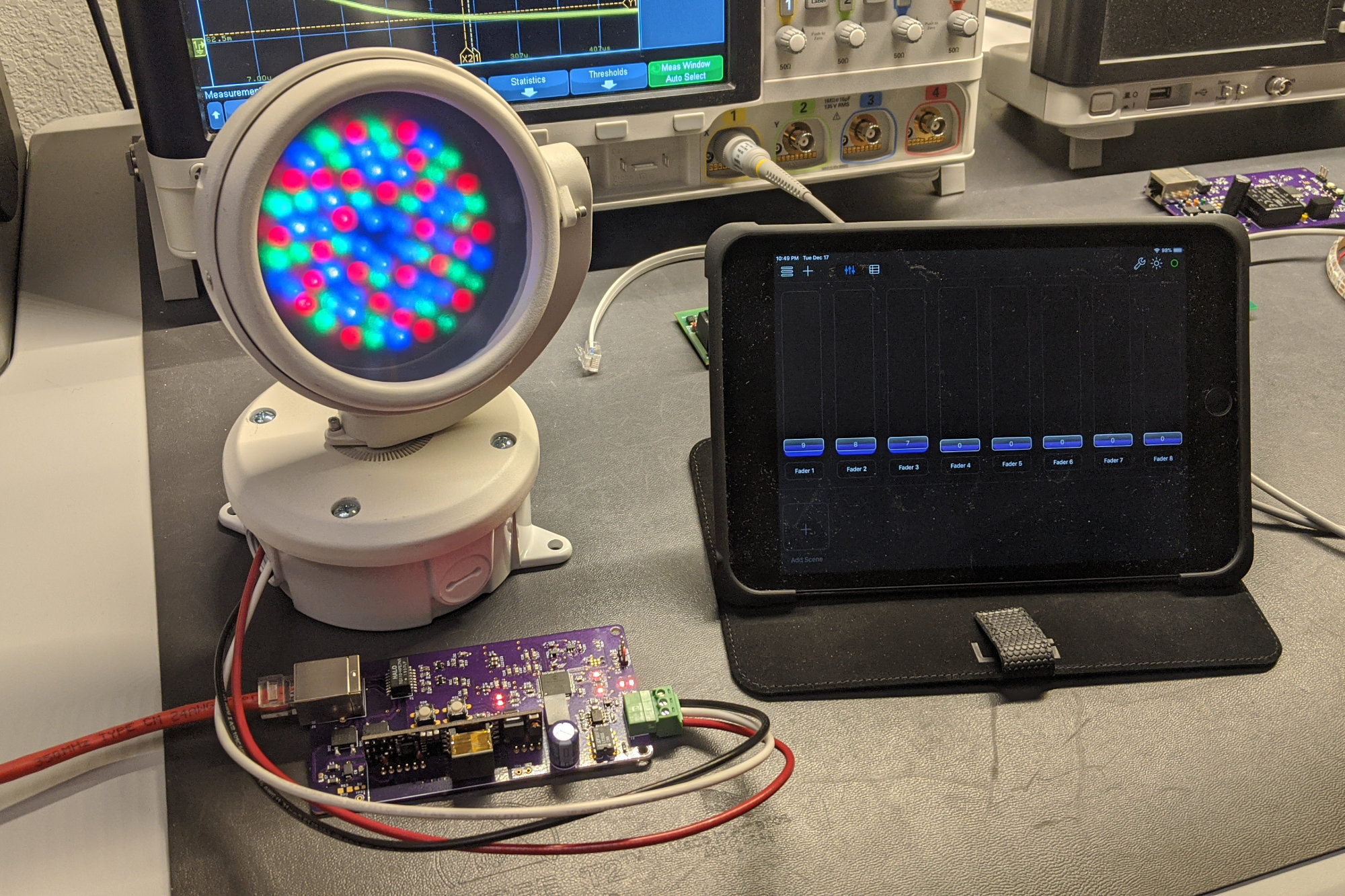
For this project, I’m going to replace the PDS-150e with a small power / control board that can directly power and control a single 10 watt ColorBurst 4 fixture from any 802.3at / PoE+ capable switch and an industry-standard Art-Net controller sitting anywhere on the network. I’ll use Synthe-FX’s Luminair 3 software running on an iPad Mini to send Art-Net packets to the board and control the light.
A Silvertel PoE module will handle the 802.3at classification and supply a regulated and isolated 24 volts for powering the fixture. A PIC18F67J60 will handle the data side of the project by accepting Art-Net packets and converting them to a serial DMX-512 stream to control the light. Finally, the project will use a line driver to step up the inverted 3.3 volt DMX-512 serial bitstream to a 24 volt version that is compatible with the fixture.
The Schematic
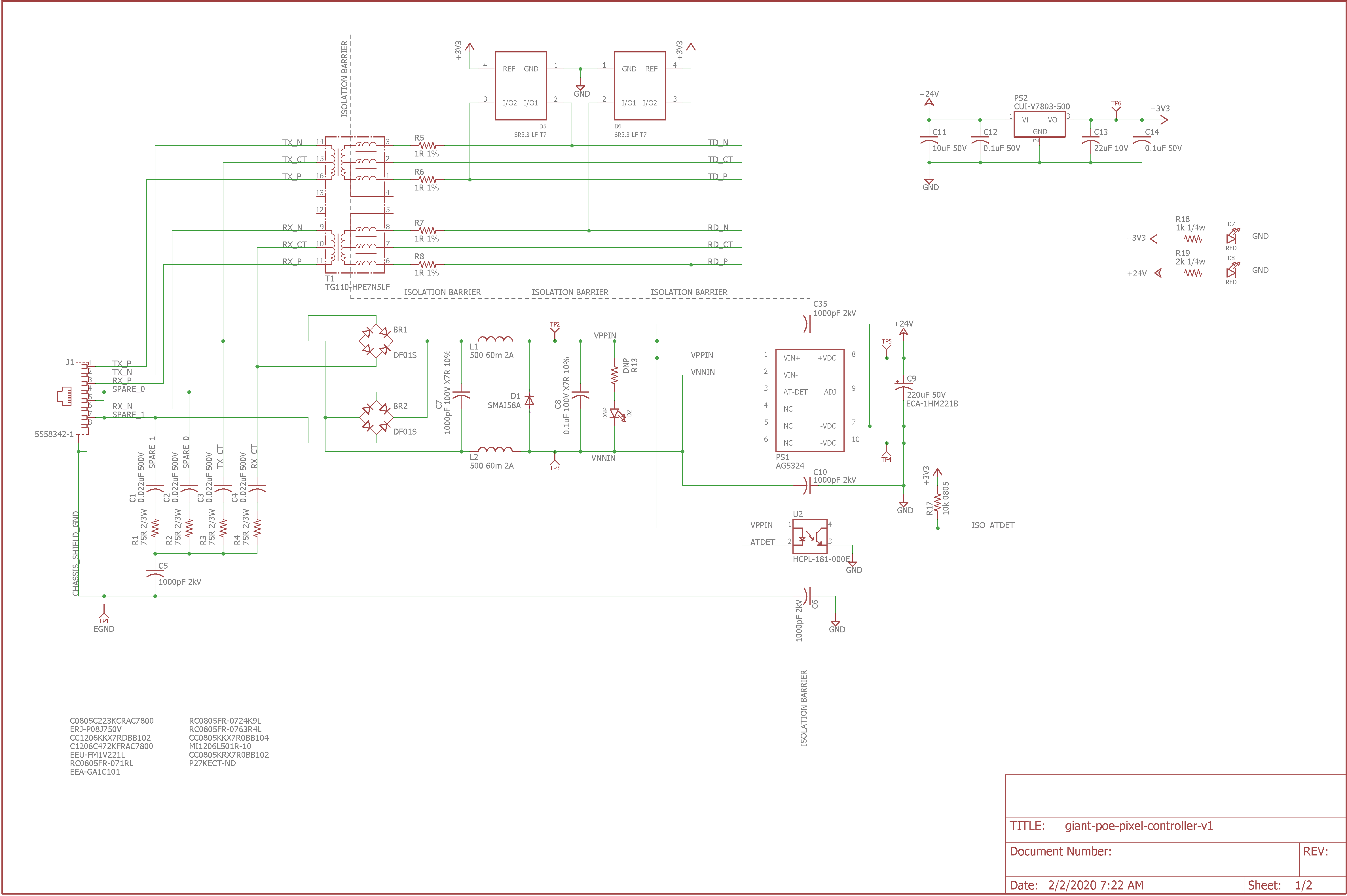
Schematic page one.
Page one of the schematic is shown above. It’s basically the same as page one of the schematic for the Ethernet-powered pixels project except the Texas Instrument PoE classification IC and the Cui 5 volt DC/DC converter have been replaced by the Silvertel Ag5324 PoE module.
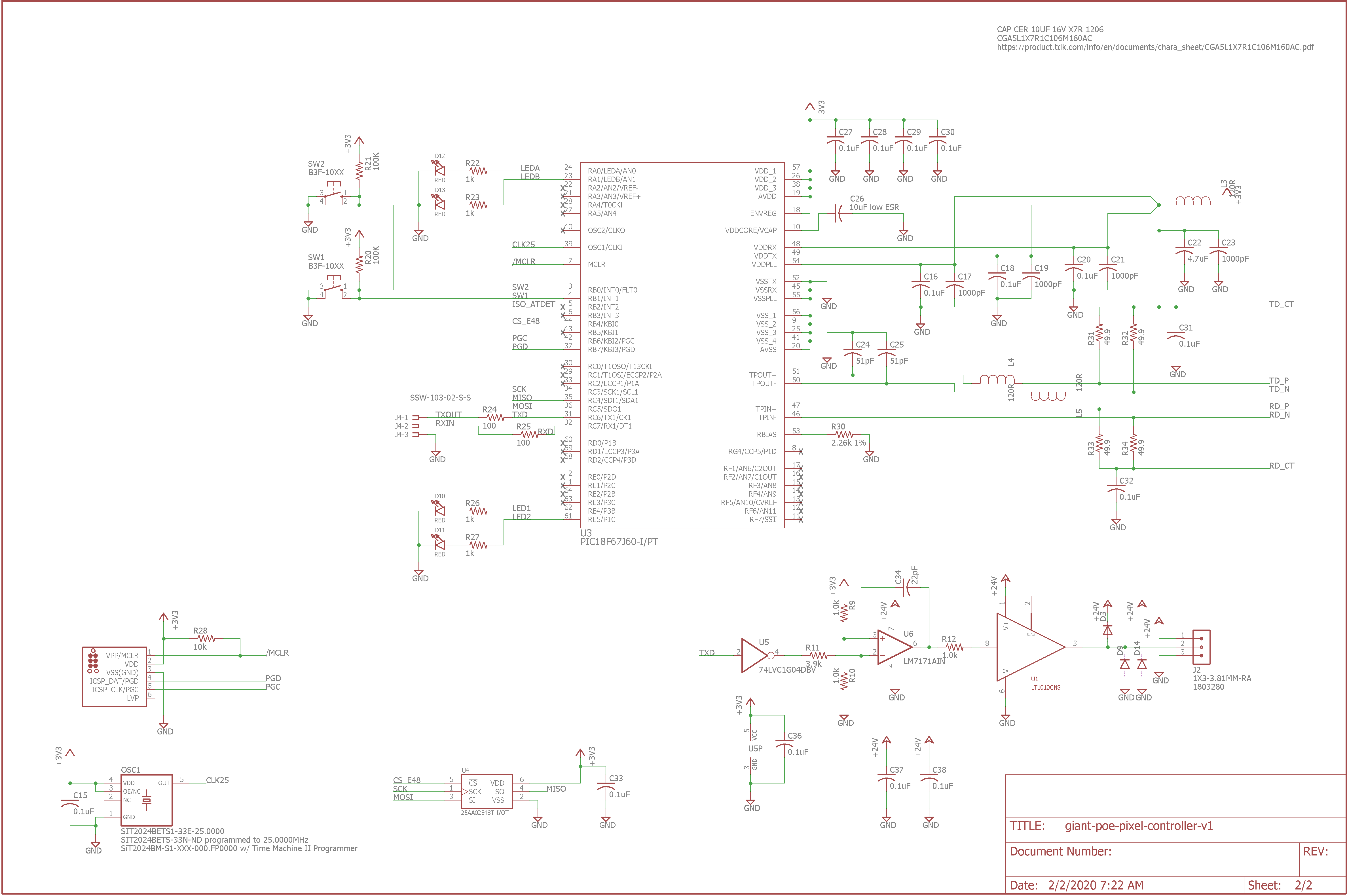
Schematic page two.
Page two of the schematic is shown above. It’s basically the same as page two of the schematic for the Ethernet-powered pixels project except the WS2812 5 volt level shifter and ESD protection circuitry has been removed. In its place is a circuit reverse engineered from a Color Kinetics PDS-60 24 volt power supply to drive the 24 volt inverted DMX protocol to the ColorBurst 4 fixture from the microcontrollers’ 3.3 volt output.
If you have questions about the parts used on this project, I highly recommend reviewing the Ethernet-powered pixels project. It goes in-depth on the selection of parts used for that project, most of which are also used on this project.
The Board Layout
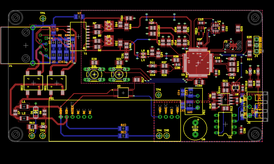
Finished board layout.
After finishing the schematic, I designed the circuit board. I attempted to place the components a bit closer together on this project versus the Ethernet-powered pixels project.
A primary concern while designing this board was to maintain at least 50 to 60 mils separation between the PoE power circuitry and the microcontroller circuitry. I don’t have the equipment to test whether this board layout successfully passes the 802.3 isolation requirements but with this separation, it at least stands a chance.
I ordered the boards from OSH Park and put together a bill-of-materials with their corresponding Digi-Key part numbers. Once I received notification that the boards had shipped from OSH Park, I ordered the parts from Digi-Key. This way I’d get the boards and the parts around the same time.
Power Supply Bring Up
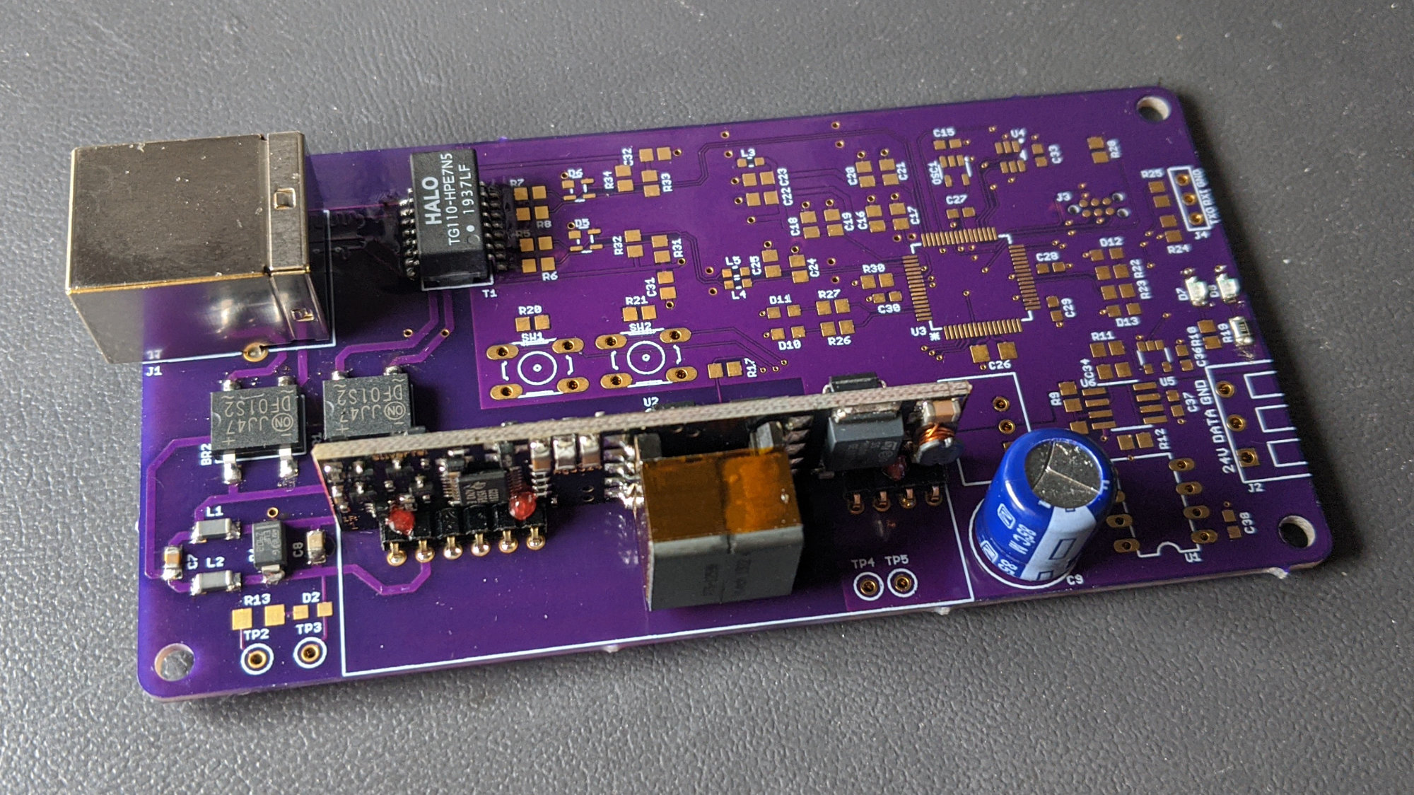
The PoE-powered RGB LED floodlight controller with the PoE and power supply circuitry populated.
After receiving the boards back from OSH Park, I brought up the PoE and power supply circuitry first. Since I learned on the Ethernet-powered pixels project not to put an LED across the rectified power from the Ethernet transformer, this board came up immediately. I used a DMM to verify the output of the Silvertel PoE module was 24 volts and I verified the board showed up as an unknown 802.3at / PoE+ device on my switch port.
Microcontroller Bring Up
The fully populated PoE-powered RGB LED floodlight controller board.
My parts order for the rest of the board arrived a bit late but I had enough parts on hand to populate the 3.3 volt power supply and the PIC18F67J60 microcontroller. I did not have the parts for the Ethernet signals or the 25 MHz oscillator so the Ethernet bring up would have to wait for later.
I created a new XC8 project in MPLAB X IDE that used the internal oscillator on the PIC to blink the four LEDs slowly in succession. This was enough software to verify the microcontroller could be programmed and debugged. I downloaded the software and the lights blinked exactly as expected.
Once the rest of the parts arrived, I populated the remainder of the board including the Ethernet circuitry, the SiTime MEMS 25 MHz oscillator, the EUI-48 serial EEPROM, and the 3.3 volt inverted serial to 24 volt inverted serial driver.
To verify the Ethernet circuitry worked, I downloaded the build of the software for the Ethernet-powered pixels project to this board. This build could not control the ColorBurst 4 LED floodlight but it would attempt to get an IP address using DHCP from my router which was enough functionality to verify the Ethernet circuitry functioned correctly.
When I plugged the board into my switch, the board powered up and received an IP address from my router. I noted that a new MAC address had appeared on my network and this MAC address was the same MAC address as the one programmed in the EUI-48. The Ethernet circuitry works!
The next step was to clone the software for the Ethernet-powered pixels project to a new project and modify the Art-Net UDP receive routine to send the first three channels of level data to the ColorBurst 4 fixture as DMX data. I wrote the quick DMX send routine shown below then downloaded the code to the board.
        INTERRUPT_GlobalInterruptDisable();
        INTERRUPT_PeripheralInterruptDisable();

        // send break
        TRISCbits.TRISC6 = 0;
        LATCbits.LATC6 = 0;
        RCSTA1bits.SPEN = 0;

        __delay_us (88);

        // send mark after break
        RCSTA1bits.SPEN = 1;

        __delay_us (8);

        // send 0x00 followed by three art-net data bytes
        EUSART1_Write (0x00);
        EUSART1_Write (giantR);
        EUSART1_Write (giantG);
        EUSART1_Write (giantB);

        INTERRUPT_GlobalInterruptEnable();
        INTERRUPT_PeripheralInterruptEnable();
I used an oscilloscope to verify the serial data ranged from 0 to 24 volts and the baud rate was correct. After that, I connected the ColorBurst 4 fixture to the board. The light powered up but did not respond to the levels set on my Art-Net controller. Using the scope I could see DMX packets being sent to the light with transmitted levels corresponding to the levels set by the Art-Net controller but the light did not respond.
Finally, I looked at the DMX-512 spec again. It requires two stop bits. The PIC18F67J60 doesn’t support two stop bits but it does support a 9-bit data transmission mode. I enabled the mode and set the 9th bit to always be a ‘1’. That generates a signal identical to a signal with two stop bits.
        // enable 9 bit mode
        TXSTA1bits.TX9 = 1;
        TXSTA1bits.TX9D = 1;
I downloaded the code to the board again and this time, success! The ColorBurst 4 responded as I varied the level sliders on my Art-Net controller software.
Putting It All Together
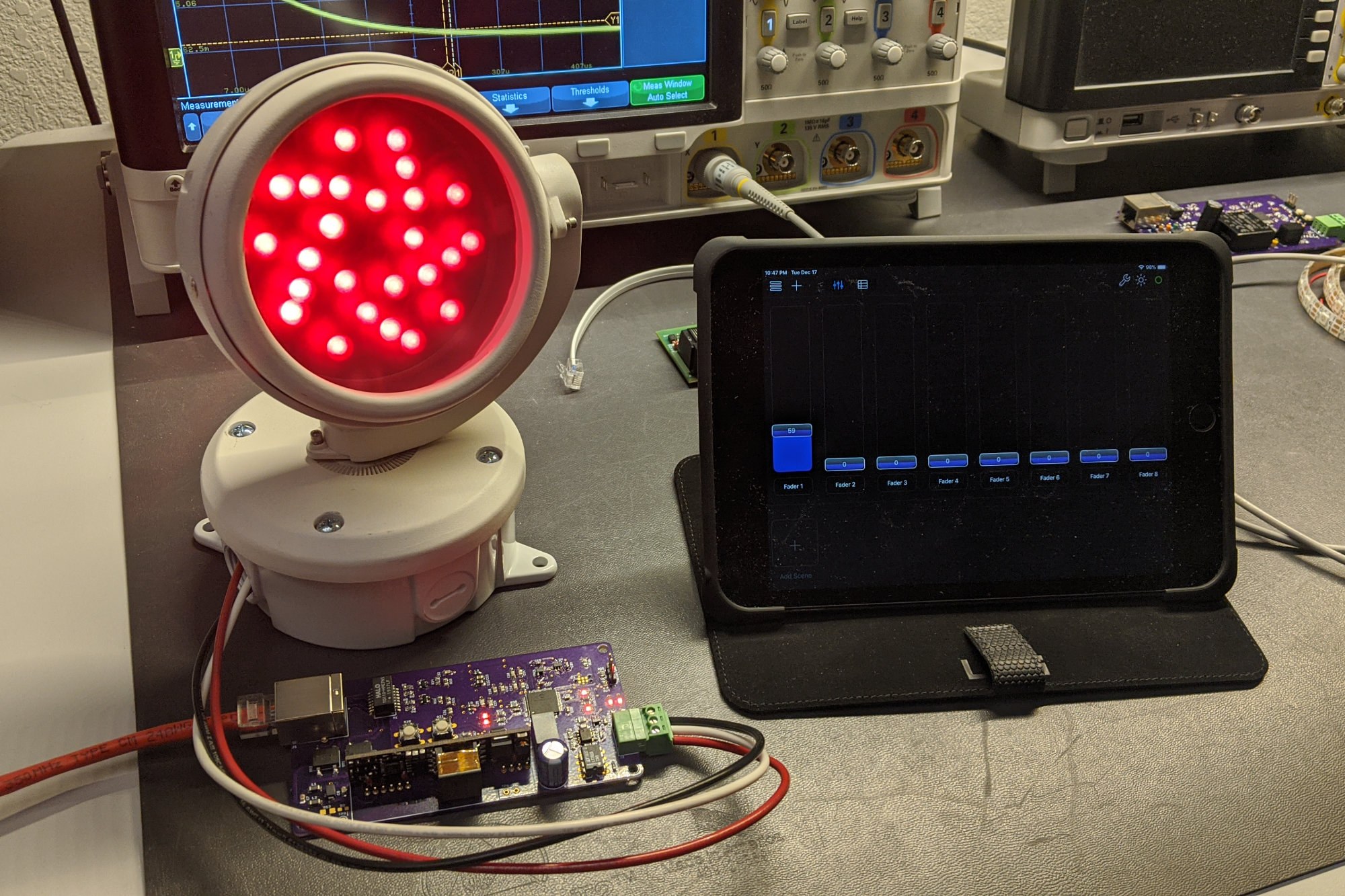
The RGB LED floodlight being powered and controlled over the network. I’m using Luminair 3 by Synthe-FX on an iPad mini to send the Art-Net packets and control the LED fixture.
This project was successful. I could use software running on my iPad Mini to control the brightness and color of the light emitted by the ColorBurst 4 LED fixture and the fixture was powered using 802.3at PoE+ from my Ethernet switch.
A possible future iteration of this project might be to build my own RGB LED fixture, integrate the PoE+ power supply and Art-Net control circuitry in to the fixture, and design an enclosure to hold and cool everything. The enclosure would need to have a means for aiming it and securing it in position, a transparent or frosted window for the light, and an Ethernet jack on the back or bottom for powering and controlling the light.
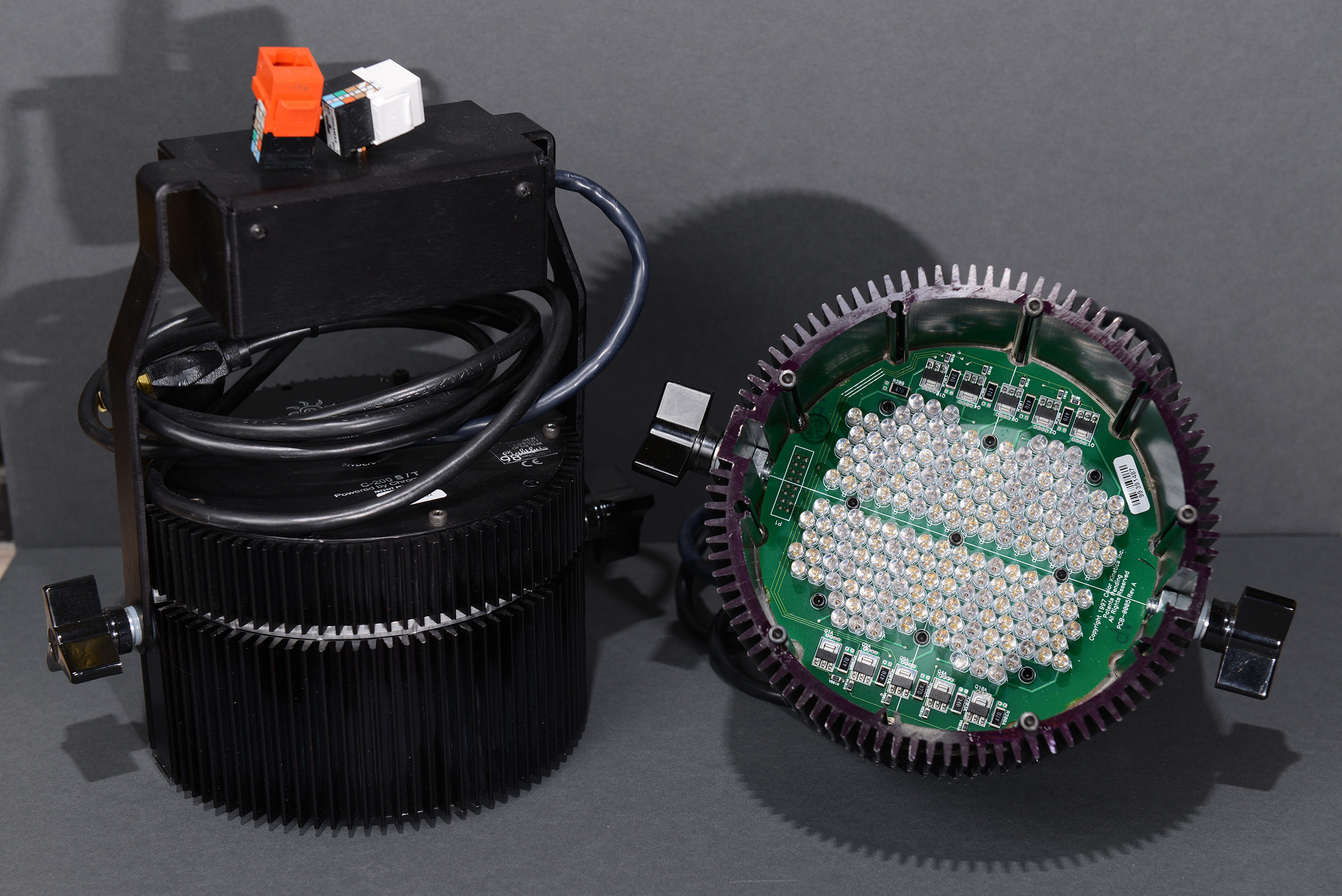
Color Kinetics C200 RGB LED track fixtures hacked to be usable without the track.
Another thought would be to replace the control board in one of the older style Color Kinetics C-200 fixtures shown above with a board of my own design that includes PoE and controller functionality then cut a new rear panel for the light with just an opening for an Ethernet jack on it. This could be tricky depending on the amount of space available in the fixture.
Design Files
The design files for this project are on Github. You can reach me about any missing files or other questions on Twitter @bikerglen.