Building an Enclosure using SketchUp and 3D Printing

3D printed enclosures designed using SketchUp

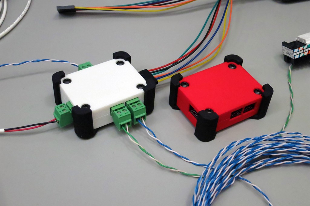
The image above shows two enclosures for a printed circuit board design. These were designed using the inexpensive hobbyist version of CadSoft Eagle and the free maker version of Trimble SketchUp. The free version NetFabb Basic was used to check the design for manufacturing. The enclosures were finally 3D printed at shapeways.com using their EOS Formiga P110 SLS 3D printers. Read on to see some of the lessons I learned while designing and printing these enclosures.

Continue reading

Posted in 3D CAD/CAM, 3D Printing, SketchUp | Comments Off on Building an Enclosure using SketchUp and 3D Printing

Folding the Six Panel Wall into a Cube

After seeing this cube and this cube, I decided it was time to build an LED cube of my own leveraging the BeagleBone Black and FPGA work I had already done for my six-panel mini video wall. The cube project is essentially purely mechanical since the existing BBB software and FPGA code will work unmodified to drive the cube.

The finished cube hanging from the rafters in my basement.

Continue reading

Posted in BeagleBone Black, FPGA, LED Matrix, Lighting, RGB LED | Comments Off on Folding the Six Panel Wall into a Cube

Expanding the BeagleBone Black and FPGA to Drive 6 (or more) Panels

After completing my first BeagleBone Black + FPGA project and tutorial where I drove a single 32×32 RGB LED matrix, I decided it was time to go bigger. The result is the project shown below—a 3 x 2 matrix of 32×32 RGB LED panels. That’s 6,144 RGB LEDs or 18,432 LED chips—each of which can be controlled with 12-bit color at a refresh rate of 200Hz. Let’s take a closer look at the steps required to move from driving one panel to driving six panels.

Here is a video on YouTube of the six panel project in action.

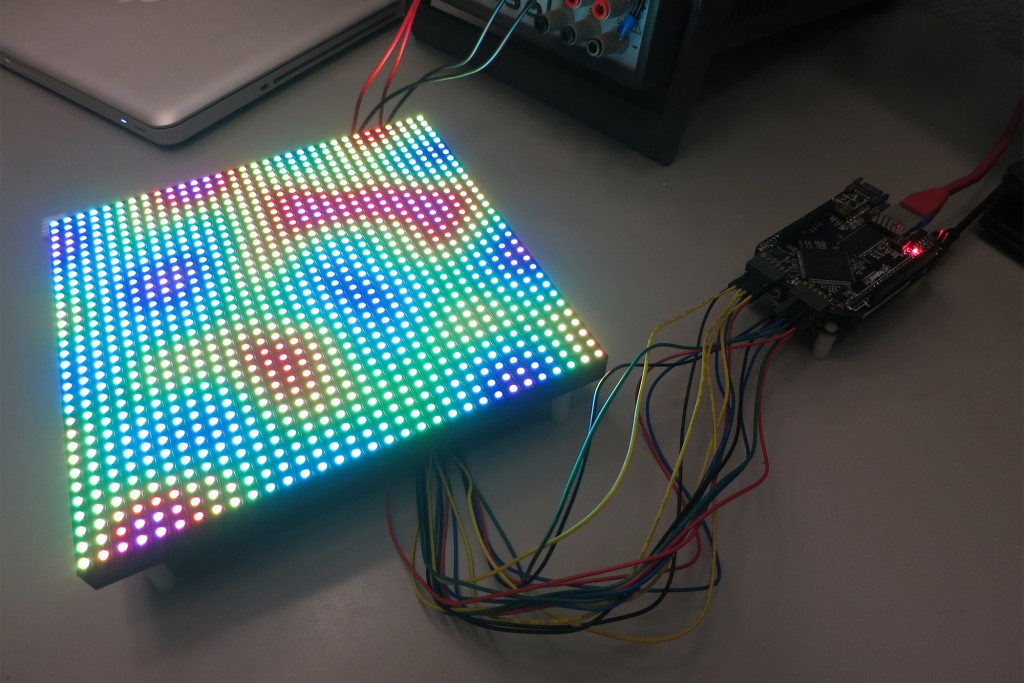
576mm x 384mm RGB LED “wall” displaying a frame of Perlin noise. The BeagleBone Black can perform the roughly 600,000 3D Perlin noise calculations required to produce a smooth animation sequence at about 50% CPU utilization.

576mm x 384mm RGB LED “wall” construction showing six 192mm x 192mm 32x32 RGB LED panels, the 3mm thick aluminum frame, two pieces of 20x40mm aluminum extrusion, wall mounting brackets, electronics, and power supply.

Continue reading

Posted in BeagleBone Black, FPGA, LED Matrix, Lighting, RGB LED | Comments Off on Expanding the BeagleBone Black and FPGA to Drive 6 (or more) Panels

Driving a 32×32 RGB LED Matrix with a BeagleBone Black and an FPGA

My latest project uses a BeagleBone Black and a Xilinx Spartan 6 LX9 FPGA to drive a 32×32 RGB LED matrix.

BeagleBone Black + LogiBone FPGA board driving a SparkFun 32x32 RGB LED panel.The displayed pattern is a frame from a Perlin noise pseudorandom sequence.

This project lets me display cool and interesting patterns on a matrix of 32×32 RGB LEDs. That’s 1024 RGB LEDs or 3072 individual LED chips that need to be controlled! Rather than attempt to control all the LEDs in software only or using one of the BBB’s programmable real-time units (PRU), I decided to use the CPU to generate the patterns and use the FPGA to handle the heavy duty task of refreshing the LEDs.

Continue reading

Posted in BeagleBone Black, FPGA, LED Matrix, Lighting, RGB LED | Comments Off on Driving a 32×32 RGB LED Matrix with a BeagleBone Black and an FPGA

Trailview 360° Camera Panorama Viewer

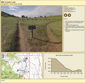
Here’s a screen shot from the proof-of-concept demonstration of my trailview camera javascript viewer:

The actual viewer is located here:

Panoramic Trail Viewer – Mill Creek Link

Be patient. Images are rendered using HTML5 canvases and each panorama is an eight-megapixel, 2MB file. It can take a few seconds to download an image from the server and another 5 to 10 seconds to decompress the image. Once the image is loaded, panning and zooming are actually quite smooth. I’ve tested this with Firefox, Safari, and Chrome on a Mac. Tablets and phones don’t have enough horsepower for the large images. IE on Windows is known not to work. Like I said, it’s a proof of concept.

The upper left corner is the panoramic image which can be scrolled a full 360 degrees by 180 degrees by clicking and dragging the mouse. My camera only captures 360 by 90 degrees so the ground and sky appear as dark grey regions. The image can be zoomed in and out using the mouse wheel.

The upper right corner is the status display. The status display displays the user’s compass heading as well as the trail relative heading with 0° representing the down trail direction (walking from the green start flag to the red end flag) and 180° representing the up trail direction (walking from the red end flag to the green start flag). Camera angles and panorama numbers are displayed here too.

The lower left corner is a map displaying the user’s current position on the trail. The green flag is the start of the trail, the red flag is the end of the trail, the blue line is the trail, and the green dot is the user’s current position. The user’s current position can be moved by clicking on the trail.

The lower right corner is an elevation profile of the trail. The green dot represents the user’s current position. The user’s current position can be moved by clicking on the profile.

For more information on the DIY 360 degree panoramic camera rig I used to take the panoramas, please watch my youtube video:

360 Panorama Camera Built with GoPro Hero 2 Cameras

It’s constructed from an aluminum housing, four GoPro Hero 2 cameras, a control board I built, and a tilt-compensated electronic compass. It’s controlled over Bluetooth from my Android phone.

A final note: Google Maps has a Streetview API that would permit these same panoramas to be displayed very quickly using their Streetview software. I may move to that in the future but I wanted the first version to be completely self-contained and work without a continuous connection to the Internet.

Posted in Trailview, Trailview Software | Comments Off on Trailview 360° Camera Panorama Viewer