

LED and driver boards used to turn bulky, current-hungry Allen Bradley incandescent cluster pilot lights into something more hacker friendly.
I was recently working on a project and wanted to incorporate one of Allen Bradley’s four-position, four-color cluster pilot lights into the project. A quick search of eBay found several lights with the lens colors I wanted but not at the voltage I wanted. Furthermore, the lights were all incandescent and illuminating just a single segment would pull almost 200mA at 6V. That’s a bit more current and voltage than I could supply from a 3.3V microcontroller or FPGA pin. I went ahead and ordered a few complete lights that had the colored lenses I wanted and hoped I could find some way to replace the incandescent bulbs with current-sipping LEDs.
Background
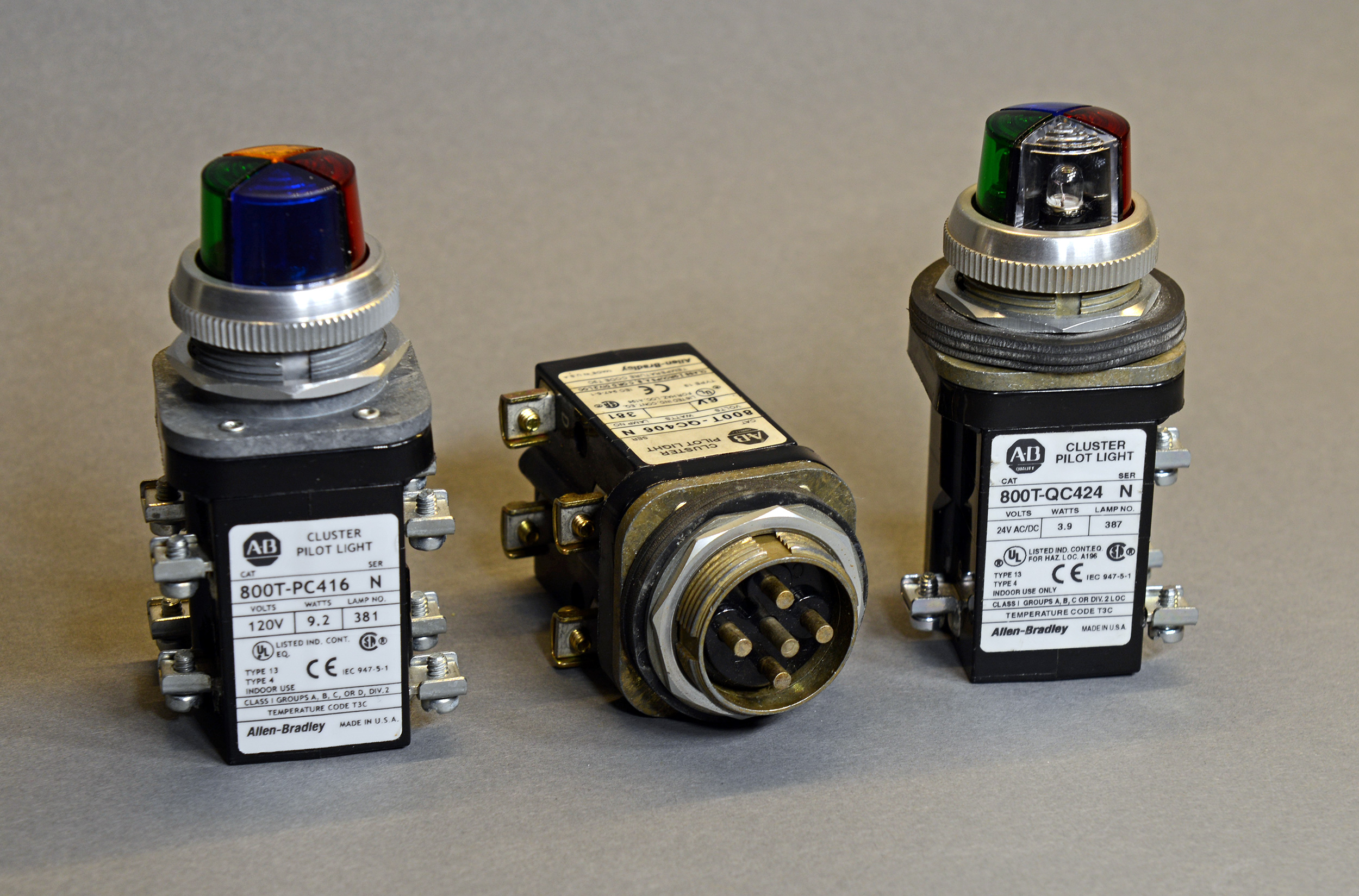
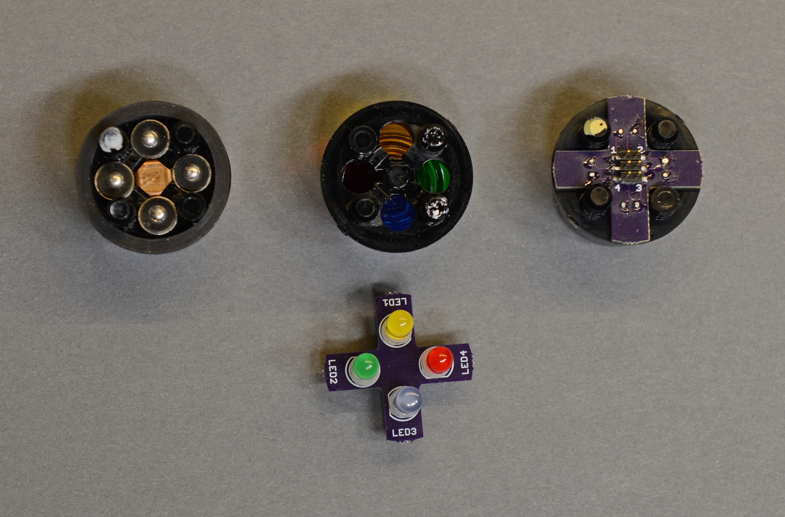
Allen Bradley cluster pilot lights in their original state. Left to right: 120VAC transformer version, 6VDC direct voltage version, and 24VDC direct voltage version.
The picture above shows three Allen Bradley cluster pilot lights in their original state. The one on the left is a 120VAC transformer version. It’s heavy because it contains four transformers that step down 120VAC to about 6VAC to power the incandescent bulbs inside the lens.
The middle light is a direct voltage version with the lens removed and the right light is a direct voltage version with the lens still in place. These are quite a bit lighter than the transformer version because they don’t have transformers inside them. The voltage applied to the terminals is applied directly to the bulbs inside the lens. The middle one is a 6V version and the right one is a 24V version. Other than the labels and the voltage rating of the bulbs inside the lens, they’re identical for all practical purposes.
Base to Lens Electrical Connections
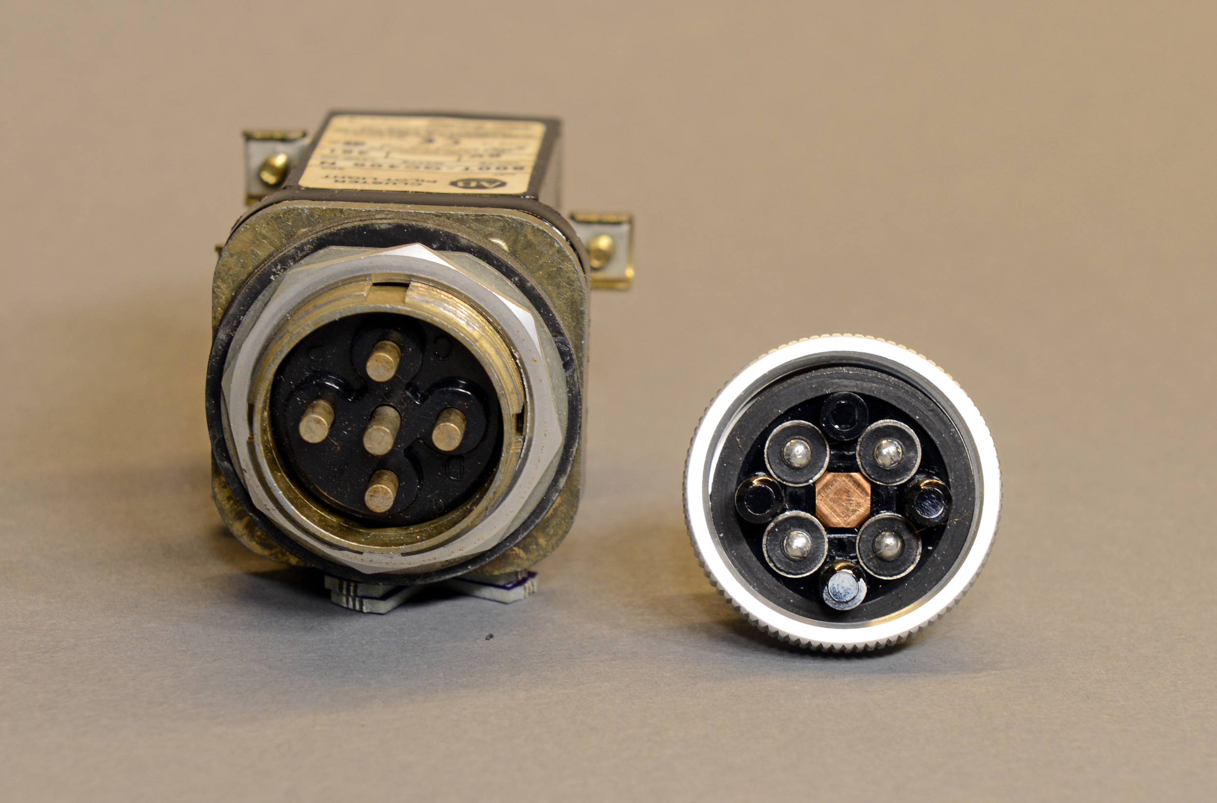
Left: Pogo pins in the cluster pilot light base. Right: Mating contacts on the bases of the bulbs and on the copper center common contact inside the cluster pilot light lens.
The cluster pilot light base on the left has five spring-loaded pogo pins. The cluster pilot light lens on the right has four bulbs around the outside edge and a copper center common contact. When the lens is placed on the base, the spring loaded contacts in the base make contact with the base of each bulb and the common copper contact in the middle. In the direct voltage version, the pogo pins are connected directly to the screw terminals on the base. Applying a voltage across the A and common screw terminals then results in a voltage across the base of the A bulb and the copper center common contact thus lighting up the A bulb. The lens is keyed so that it will only fit on the base in a single orientation.
The Plan
By this point a plan was forming. I wanted to design an LED board that fit inside the lens cap and held the LEDs in place. This board and the LEDs would completely replace the bulbs, the copper center common contact, and most of the base of the cluster light. But I still wanted to be able to panel mount the hacked cluster pilot light so I needed to separate the threaded panel mounting collar from the black plastic portion of the base.
Separating the Threads from the Rest of the Base
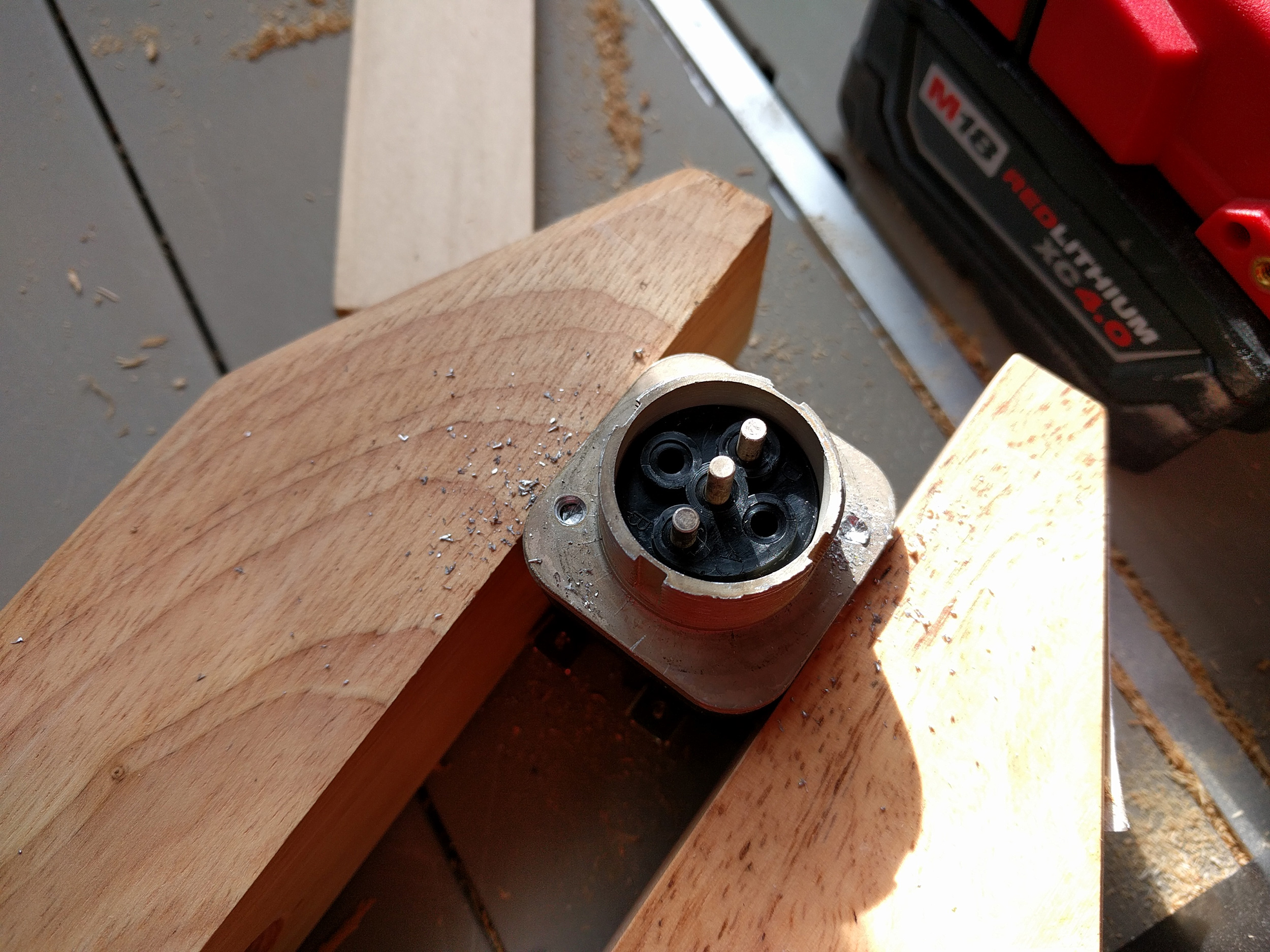
Drilling out the rivets—one rivet down, second rivet half way done.
The threaded collar is held on to the rest of the cluster pilot base using two rivets. I decided to try to drill these out using a drill bit slight larger than the head of the rivet. The first rivet came out right away. I paused to take a photo before completely drilling out the second rivet. Then success! The threaded collar was now separated from the rest of the base.

Success!
Designing the Boards
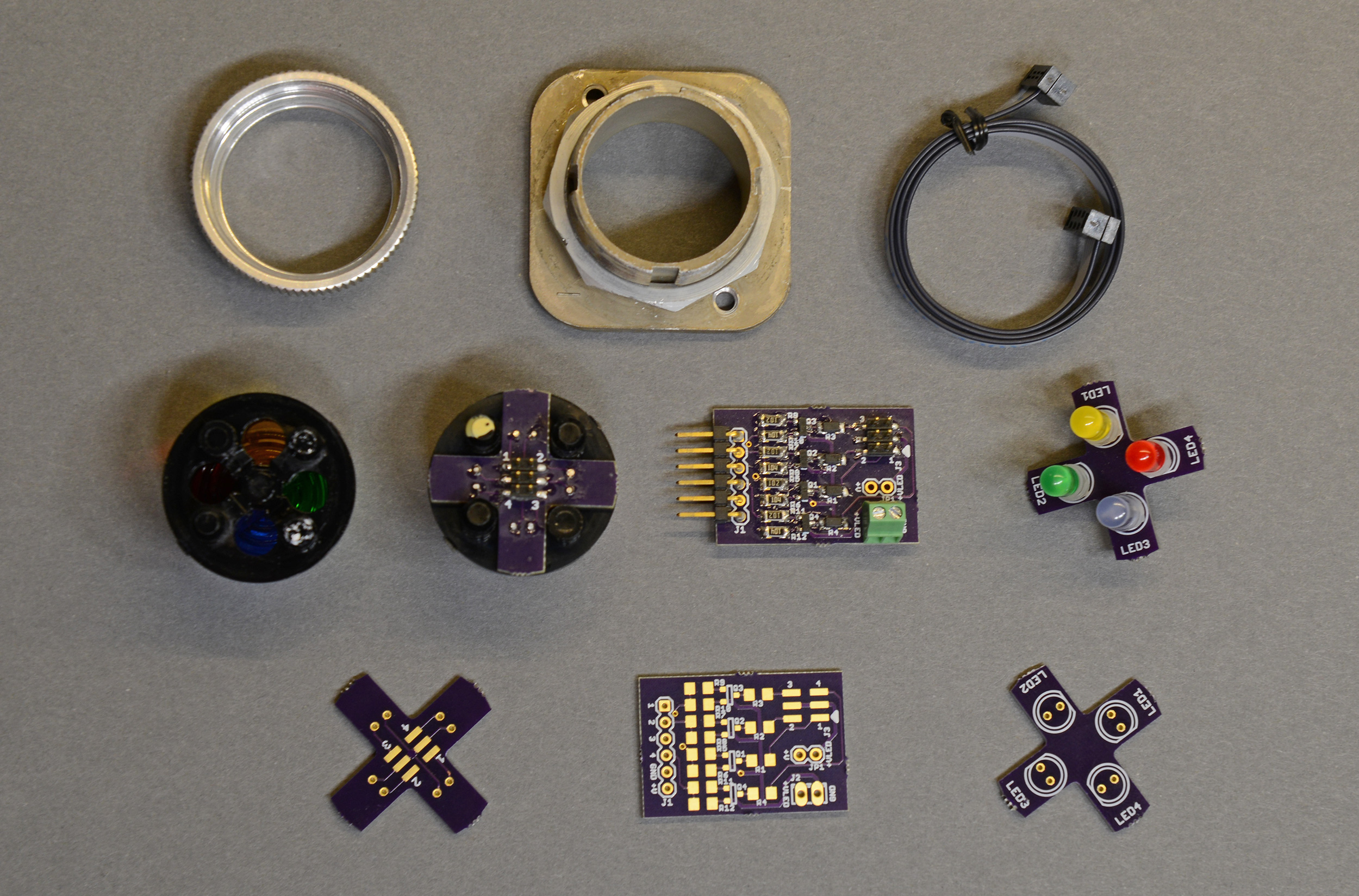
Top row, left to right: Threaded ring, threaded collar, 12” cable with six-position 2mm header sockets. Middle row, left to right: lens cap with bulbs and center copper contact removed, my LED board inserted in lens cap, my driver board, my LED board with LEDs showing. Bottom row: a few unstuffed boards.
I really wanted a single board that fit inside the lens cap but it just wasn’t going to happen. Instead, I opted to build an LED board and a driver board separated by a short cable. The driver board design is small enough it could be incorporated into the board design for a larger system if desired.
LED Board Design
To design the LED board, I used my calipers to measure the diameter of the lens assembly (middle row, leftmost item in the photo above). This measurement would be the outside diameter of my circuit board. Then I used my calipers to measure the location of the holes for the bulbs in the lens assembly. This would be the center location for each of my four LEDs. Finally, I used my calipers to measure the distance between the posts on the lens assembly. This would be the width of each of the four legs on my LED board.
After laying out the board, it quickly became apparent I did not have room for current limiting resistors or much of anything else on the LED board. I didn’t have room for a 0.1” header of any type either. After a bit of digging around, I found data sheets for a surface mount double-row, six-position, 2mm pitch header (TMM-103-01-S-D-SM) and a mating six-conductor cable (TCSD-03-D-06.00-01) from Samtec. This connector would easily fit. I dropped the SMD pads for the header on the board, wired everything up, and sent the board design out for fab.
When the LED boards were assembled and placed in the lens, the LEDs were a bit low so I used some 0.2” standoffs from Visual Communications Company to situate the LEDs a bit higher in the housing. The part number for the 0.2” standoffs is CM00624200.
I used the following LEDs:
Red 5mm led — Kingbright WP1503ID
Green 5mm led — Kingbright WP1503GD
Blue 5mm led — Kingbright WP7083QBD/G (put 220Ω 1206 resistor in parallel)
Amber 5mm led — Kingbright WP1503YD
The blue LED was a little too bright and distracting compared to the other LEDs. I decided to bleed some of the current through the LED into a resistor connected in parallel to the LED. Tacking a 1206 220Ω resistor onto the pins of the LED after it was mounted in the circuit board worked nicely.
Lens Assembly
Various stages of lens cap assembly.
To place the LED board into the lens, use a small screwdriver to pry out the four incandescent bulbs and then very carefully pry out the copper center contact. Remove the rubber gasket from the lens too. At this point, the lens will look like the lens in the top middle of the photo above. The LED board should look like the LED board in the bottom of the photo. Now turn the LED board over and place it into the lens. Be sure to align the LED colors with the lens colors.
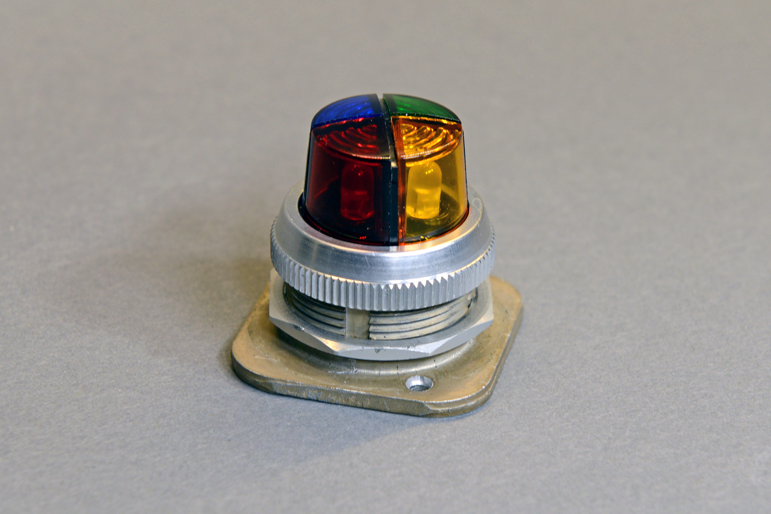
Ring, collar, LED board, and lens ready for panel mounting.
Now assemble the ring, nut, collar, LED board, and lens into a unit. At this point, the assembly can be mounted into a panel at its final location.
Driver Board Design

Cluster pilot light driver board schematic.
The goals for the driver board were to allow powering the LEDs from a single +5V supply, to supply a constant 15mA of current to each LED regardless of the LED’s forward voltage, to be able to switch the LEDs from either +3.3V or +5V, and to follow Digilent’s PMOD standard for the I/O connections to the board.
I used NPN transistors to switch each LED on or off. To supply a constant 15mA regardless of LED forward voltage, I used a linear 15mA constant current regulator from ON Semiconductor (NSI45015WT1G).
Driver Board

Assembled driver board.
The photo above shows the assembled driver board.
The LED board connects to the driver board using the double-row, six-position, 2mm pitch header in the upper right-hand corner of the board and a short cable. The +5V power supply for the LEDs connects to the green terminal block in the lower right-hand corner of the board.
The board can connect to any PMOD compatible output using the header on the left-hand side of the board. To drive the board from other devices, the ground pin on the header needs to be connected to the other device’s ground pin and pins 1 to 4 on the header need to be connected to digital outputs on the other device. A low will shut off the corresponding LED. A high will turn on the corresponding LED. This board is compatible with both +3.3V and +5V logic.
I’m powering this board from the green terminal block rather than the PMOD header so I left the +V — +VLED jumper unstuffed and unconnected.
The Finished Assembly
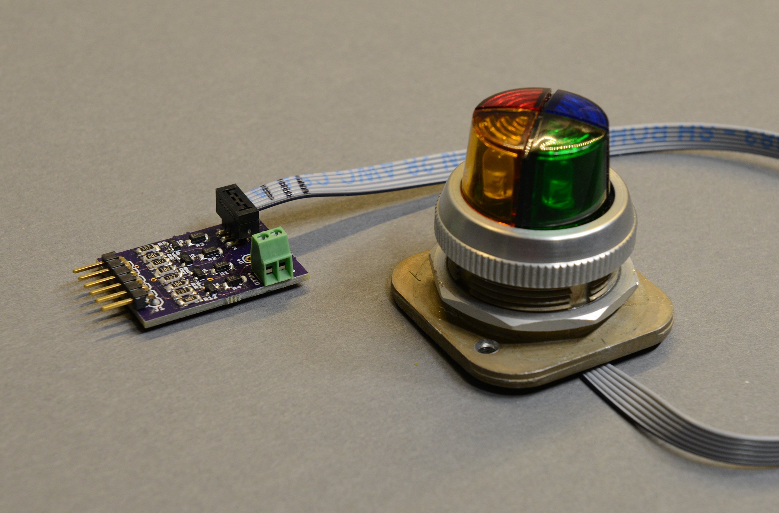
Hack complete! The finished pilot light assembly and driver board.
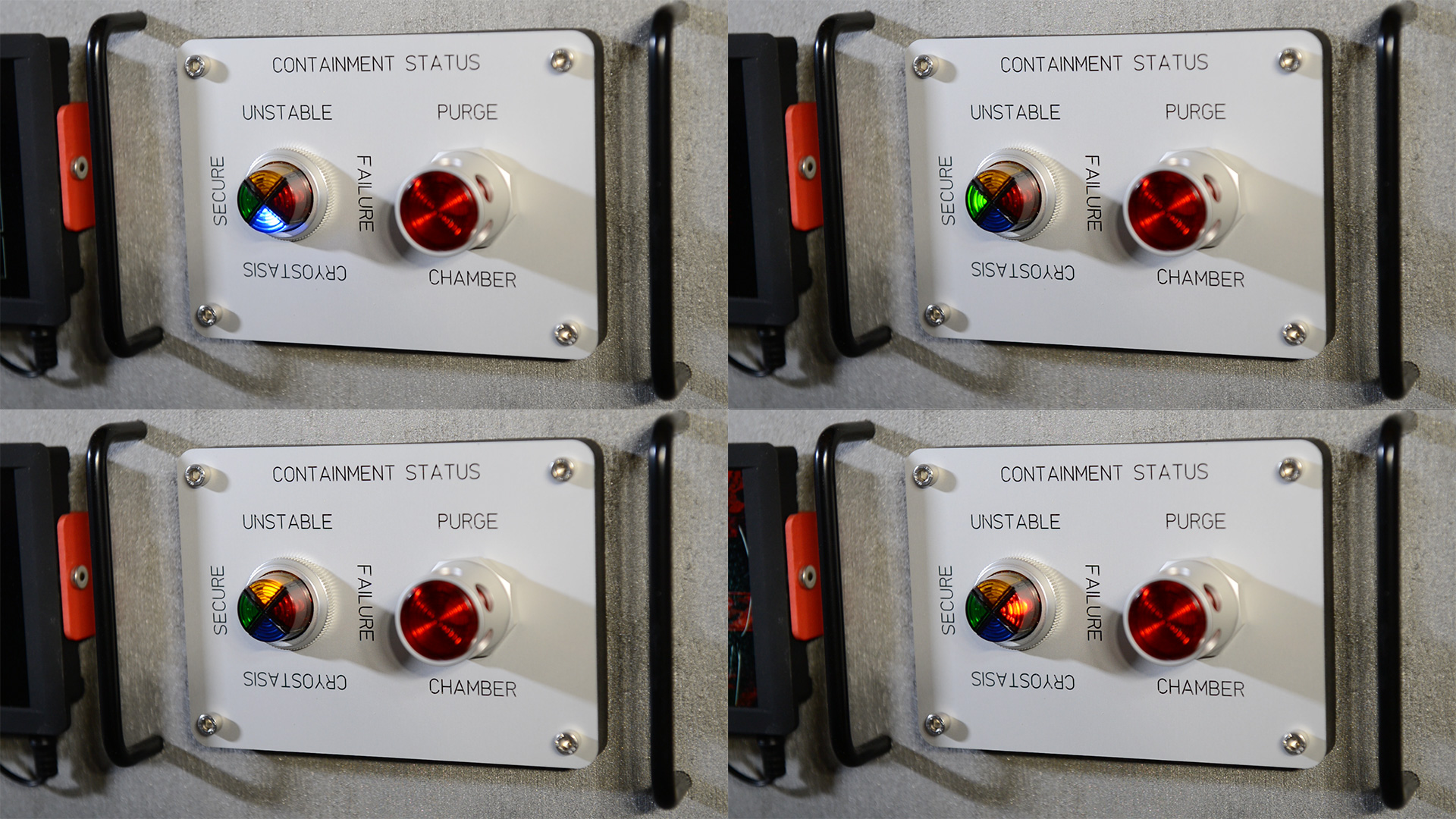
Here’s the final assembly installed and illuminated on a prop I’m building for Halloween.
Here’s the final assembly. It’s quite a bit less bulky than the stock cluster pilot light. With all four LEDs illuminated, it consumes only 60mA—less than 1/3 that of the stock cluster pilot light with just a single bulb illuminated. Finally, the LEDs can be switched on or off using +3.3V or +5V logic signals without running the LED current through the microcontroller or FPGA.