

Assembled homebrew DMX-controlled RGB LED light fixture.
This project is a small DMX-512 controlled, color-changing RGB LED light. The light can be controlled via the DMX512 protocol or it can run a number of built-in programs depending on how the software is configured. The light incorporates an advanced 16-bit PIC24 microcontroller with PWM capabilities, a 3D printed enclosure, a laser cut acrylic lid, a custom switching power supply, and a MEMS oscillator. The light measures roughly 2.25″ square by 1.25″ high. This light is the evolution of my RGB LED light designs that span back over a decade.
(This next section is long. If you want to skip the history of how this design came to be and go directly to a description of the design instead, click here.)
Early RGB LED Light Designs
The biggest influence on these RGB LED light designs has been the introduction of low-cost PCB manufacturers that cater to hobbyists and the introduction of affordable 3D printing.
Mechanical Form Factors
Early low-cost PCB manufacturing services such as those from ExpressPCB offered a fixed-sized board with two layers and no solder masks for a low cost. As a result, the board designs used through-hole components, were limited to the sizes made available by the board house unless you wanted to pay a ton extra, and you were lucky to find an interesting enclosure that would hold your board. The free PCB layout tools of the time were a bit limited too but they worked well enough for simple boards.
The photo below shows one of my designs from the early 2000s. The board is about 3″ by 2″, has through-hole components only, uses a PIC16F688 microcontroller, and uses a linear regulator to step 24V down to 5V for the microcontroller. The linear regulator is not very efficient and runs hot to the touch. The ice cube enclosure is an Ikea lamp they sold in the early 2000s. I made a ton of these as gifts for family and friends.
If you’re interested in making a color changing lamp of your own, Ikea has tons of low-cost lamps that are extremely suitable to retrofitting with your own RGB LEDs and electronics.
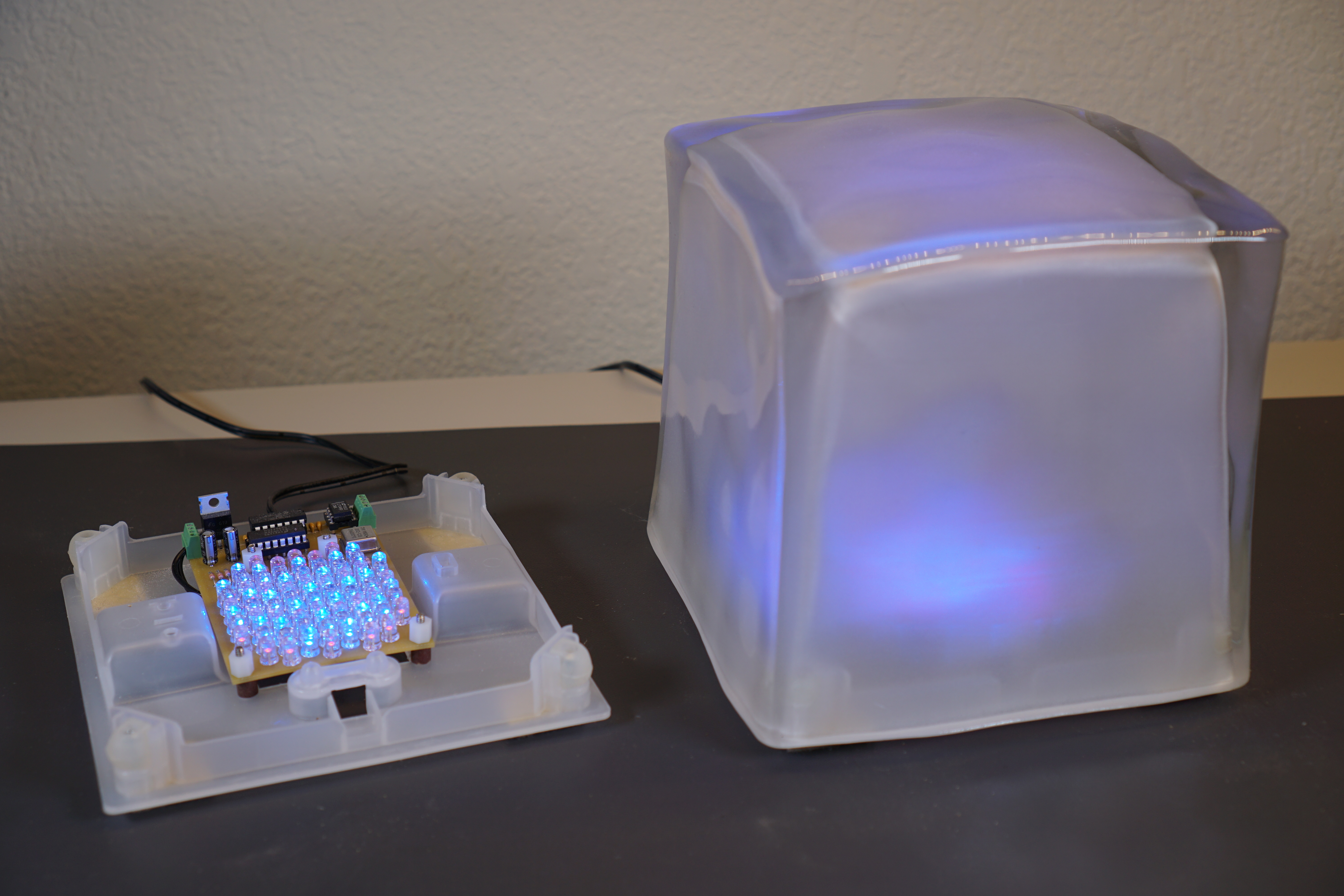
An RGB LED color changing light design of mine from the early 2000s. The circuit board was manufactured by ExpressPCB and it’s powered by a PIC16F688 microcontroller. The entire assembly was retrofitted into an ice cube lamp from Ikea.
The Early Electronics
Below is a close-up of the board from the ice cube lamp. There’s a microcontroller to control the LEDs, a Maxim part for receiving DMX, an oscillator, a linear regulator, and a transistor switch.
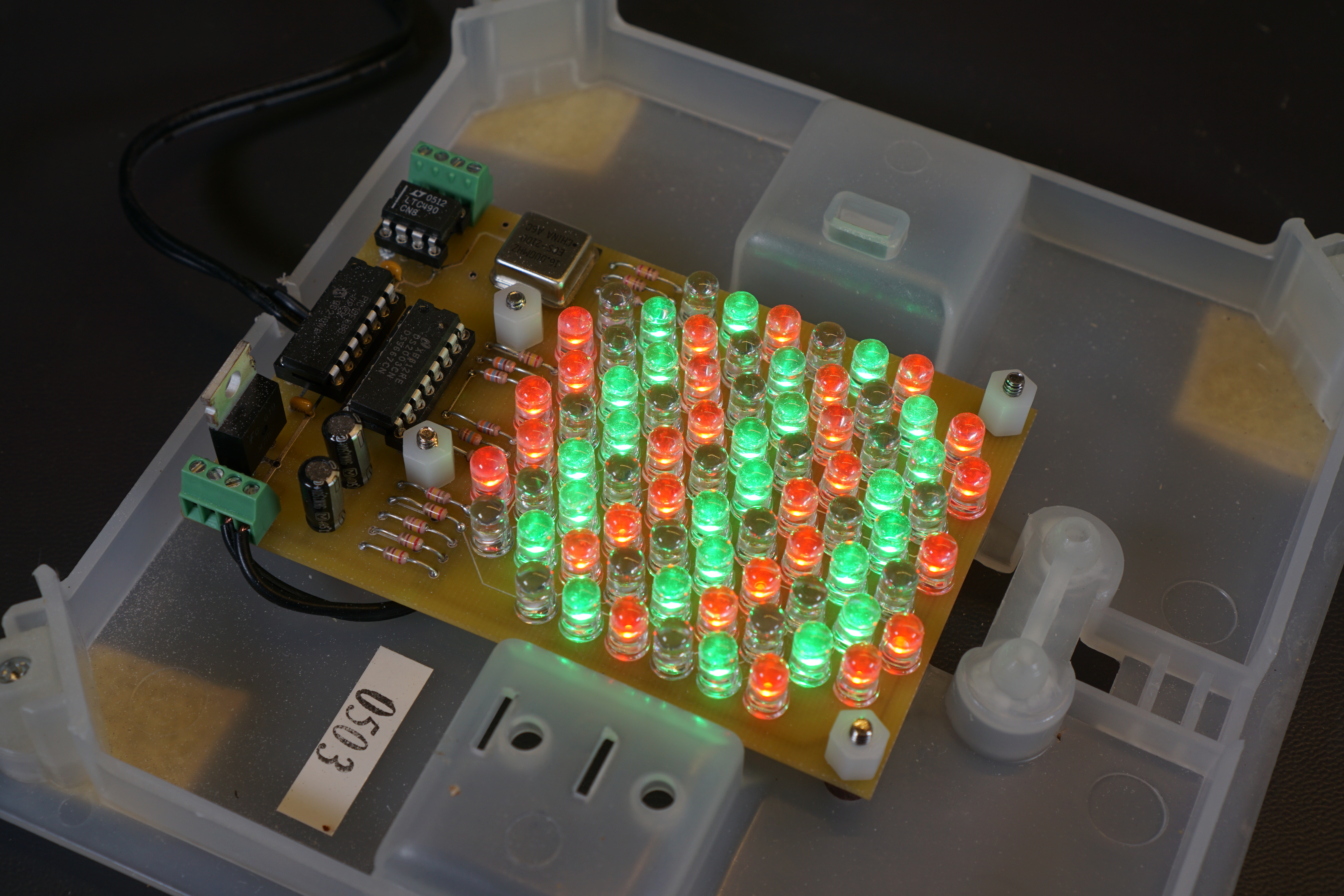
The microcontroller is a Microchip PIC16F688. The code for this microcontroller was written in assembly. PWM was initially implemented in the main loop of the code. These lights could only cycle through a serious of colors. Later PWM was implemented in an interrupt service routine (ISR). Once PWM was in the ISR, the main loop of the code was reworked to receive DMX. Now these lights could cycle through a series of colors or be controlled via DMX.
The worst part of these lights was there was no provision for in-circuit programming or debugging. The PIC16F688 supported in-circuit programming but I didn’t have room on the board for the connector. Updating the software required removing the PIC from the board, placing it in a dedicated programming fixture, re-programming the part, then placing the PIC back in the socket. For in-circuit debugging, a special bond out version of the chip had to be used.
Technology Evolves—Custom Boards and Better CPUs
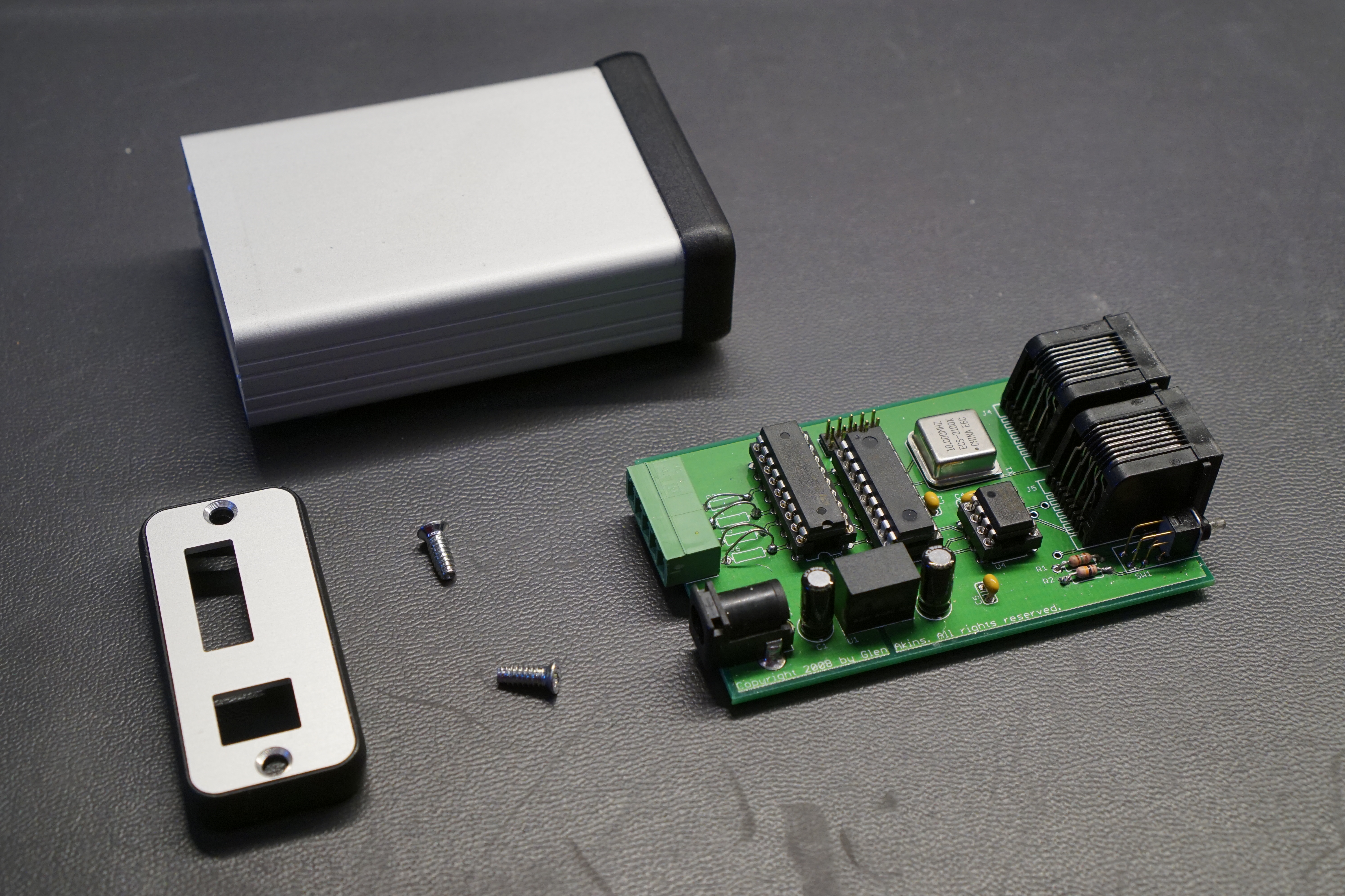
RGB LED lighting controller based on a PIC18F1320 microcontroller. Custom board size with solder masks but still using all through-hole components. This module drove a board of LEDs located in a lamp too small to hold both the LED board and driver electronics.
Custom Boards
In the late 2000s, SparkFun launched a low-cost PCB manufacturing service called BatchPCB. Pricing was $2.50 per square inch plus shipping. The service offered two layer boards with solder masks and silkscreens. They supported custom-sized boards and would even cut to a custom outline if provided. At the same time, Eagle CAD launched a free hobbyist version of their schematic capture and PCB layout tools.
These two developments suddenly allowed hobbyists to make their own high-quality custom boards of any shape and size. I took full advantage of the situation and made several new RGB LED lamps. Many of these boards were either round or designed to fit in extruded aluminum enclosures like the one in the photo above. The green boards on this blog post were all made at BatchPCB.
In 2010, DorkbotPDX launched a similar PCB batching service and opened it up to the general public. Hobbyists now had two different board services catering to small orders. DorkbotPDX eventually became oshpark.com then in 2013 SparkFun shut down Batch PCB and referred users to OSHPark. In June 2016, Autodesk purchased Eagle PCB. A free version of Eagle PCB continues to exist but users looking to upgrade to larger board areas have to move to Autodesk’s controversial pay-as-you-go usage model. For users looking for non-commercial / open source PCB CAD tools, KiCad has made terrific strides in the past two years and is now a viable alternative to Eagle PCB.
Better CPUs and Better Tools

RGB LED lamp based on a PIC18F1320 microcontroller. The PIC18 has supports in-circuit programming and debugger and has enough horsepower to do ISR-based dimming while receiving DMX-512 or commands from an IR remote control.
Around the same time as the hobbyist PCB revolution, I upgraded the microcontroller in my lights from a PIC16F688 to a PIC18F1320. The PIC18F1320 had a PC-based toolchain that included a free C compiler and debugger. Additional optimizations could be purchased for the compiler but the free version was good enough to dim the LEDs inside an interrupt service routine. No more assembly code! The PIC18F1320 also offered in-circuit programming and debugging capabilities. These two capabilities shaved tons of time off the software development process.
Evolution of Software-Based Dimming
Another change I made around this time frame was to move from pulse width modulation (PWM) dimming to pulse density modulation (PDM) dimming. In PWM dimming, the duty cycle of a fixed-frequency square wave varies from 0% to 100% to dim the LED from completely off to completely on. In PDM dimming, both the frequency and density of a series of pulses vary to dim the LED from completely off to completely on. See the figure below.
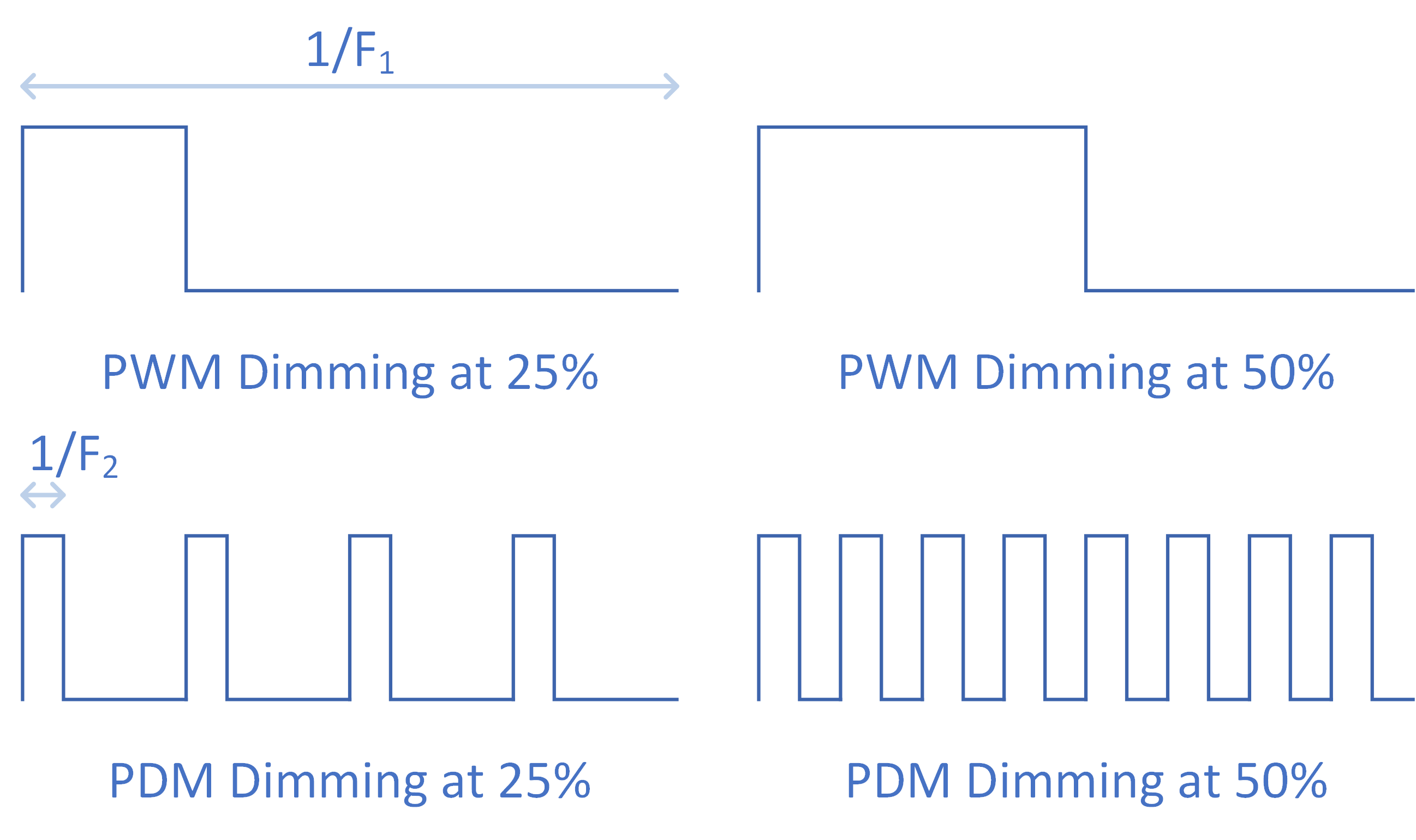
In PWM dimming, the duty cycle of a square wave varies in proportion to the commanded LED brightness. The frequency of the square wave is the frequency of the ISR timer divided by the resolution of the system. In PDM dimming, the pulse density varies in proportion to the commanded LED brightness. The maximum frequency of the pulses is the frequency of the ISR timer. PDM dimming can result in higher refresh rates and less flickering when recorded on video.
To implement PDM dimming in software a variable is used as an accumulator. At a fixed frequency inside an interrupt service routine, the commanded brightness level is added to the accumulator. If the accumulator rolls over, i.e., the carry bit is set after the add, the output pin is asserted. If the carry bit is clear, the output pin is deasserted. In some architectures, it’s possible to directly copy the carry value to the output pin without using any comparison or branch instructions.
In my implementation, the accumulator and commanded brightness are both 16 bit unsigned integers but only the lower 10 bits of the integers are used. If after an add the 11th bit is set, that’s considered a carry and the output pin is asserted. If not, the output pin is cleared. The 11th bit is then cleared in preparation for the next cycle of the algorithm. This is repeated for each of the red, green, and blue channels.
Here’s the code for the red channel:
        // default to all LEDs off
        pwm_temp = 0;

        // process red LED
        pwm_red_counter += pwm_red_level;
        if (pwm_red_counter >= 1024) {
            pwm_red_counter -= 1024;
            pwm_temp |= RED_LED_BIT;
        }

        // process remaining channels
        // ...

        // update port a
        LATA = pwm_temp;
The use of 10-bit accumulators gives 1024 distinct levels of brightness. Using 1024 levels enables better gamma correction and thus better brightness resolution particularly at lower brightness levels.
A Step Backwards for Free Compilers Necessitates the Move to Hardware PWM
Up until this point, I had been using the Windows-only MPLAB IDE and the free version of the C18 compiler. The limited optimizations of the free C18 compiler were sufficient to move in and out of the dimming ISR quickly enough to leave spare CPU cycles available in the main loop of the code.
Sometime around 2010, Microchip released the MPLAB X IDE and their new XC8 compiler. These were both cross platform and ran on Windows, Mac, and Linux. This was great. We could use the development tools wherever we wanted. Unfortunately the free version of the XC8 compiler had poorer performance when entering and exiting interrupts than the C18 compiler.
This resulted in the PIC18F1320 spending almost 100% of its time inside the ISR and as a result my ISR-based software dimming routines no longer functioned. This necessitated an upgrade to a PIC24 microcontroller with PWM done in hardware. With a PIC24 and PWM hardware, the performance of the compiler and the ISR entry/exit routines was no longer critical.
As a side note, in late 2018, I did break down and purchase the pro version of the XC8 compiler but at $1000 it’s out of reach for most hobbyists. In addition to the generated code running faster, the generated code is smaller. The pro version of the compiler is thus useful for compiling space constrained applications such as USB bootloaders and the Ethernet code included with their PoE eval board too.
Some PIC Micros Have Hardware PWM!
To take my RGB lights to the next level, I needed a better microcontroller that included hardware PWM features. Fortunately, Microchip has the Microchip Advanced Part Selector or MAPS tool. This online tool lets you perform a parametric search through all their available devices to find devices that meet your needs.
The basic requirements were a PIC24 with at least 3 PWM channels and sufficient memory to not worry about the limitations of the free compiler. One additional requirement was the availability of a low-cost development board that would permit programming and testing of the PWM peripheral without having to build my own boards.
After some searching I found my part, the PIC24EP128MC202, and development board, the Microstick II. The PIC24EP128MC202 has three channels of hardware-based 16-bit PWM. Within an hour of receiving the development board and microcontroller, I had the basic PWM functionality working. Time to design some boards.
The 6″ Strip with 16-bit PWM Dimming and Gamma Correction
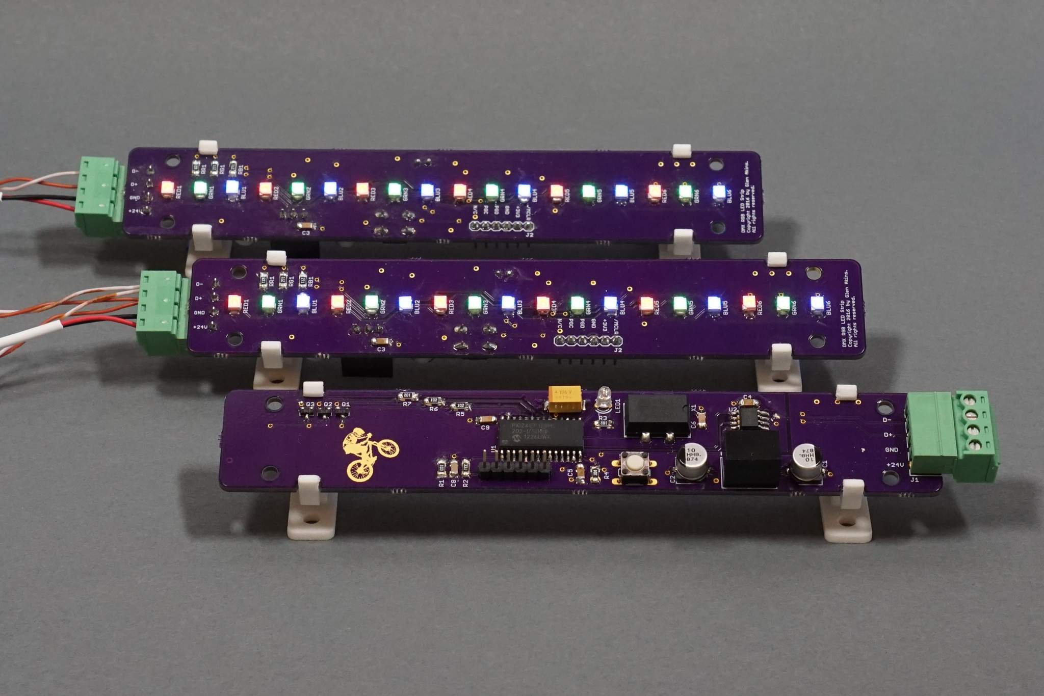
PIC24-based RGB LED Strips. Each strip is 152.4mm long and contains six of each color of LED.
The first RGB LED lamp design to use the PIC24EP128MC202 was a six-inch strip light. The strip light used six each of 3528 red, green, and blue surface mount LEDs. The board also featured slots that snapped into 3D printed tilted stands. The board was powered by 24V and had DMX control.
DIN Rail Mount
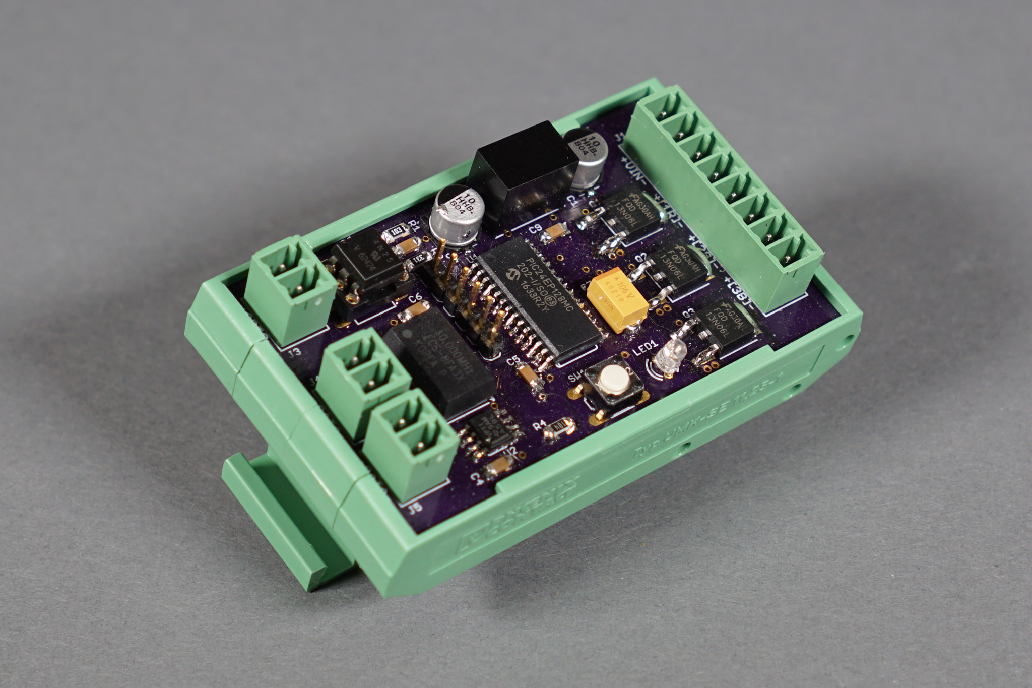
The second iteration of the PIC24EP128MC202-based RGB LED controller was designed to control LED strips for my crate beast Halloween prop. The requirements for this controller were that it be able to drive a few feet of LED strips and had a DIN-rail mount form factor so that it could be mounted beside the PLC that controlled the operation of the prop. This necessitated moving to large MOSFET power transistors instead of the smaller BJT transistors used on the strip version. Also, all I/O was placed on pluggable terminal blocks to facilitate quick repairs should they be required.
Round v1
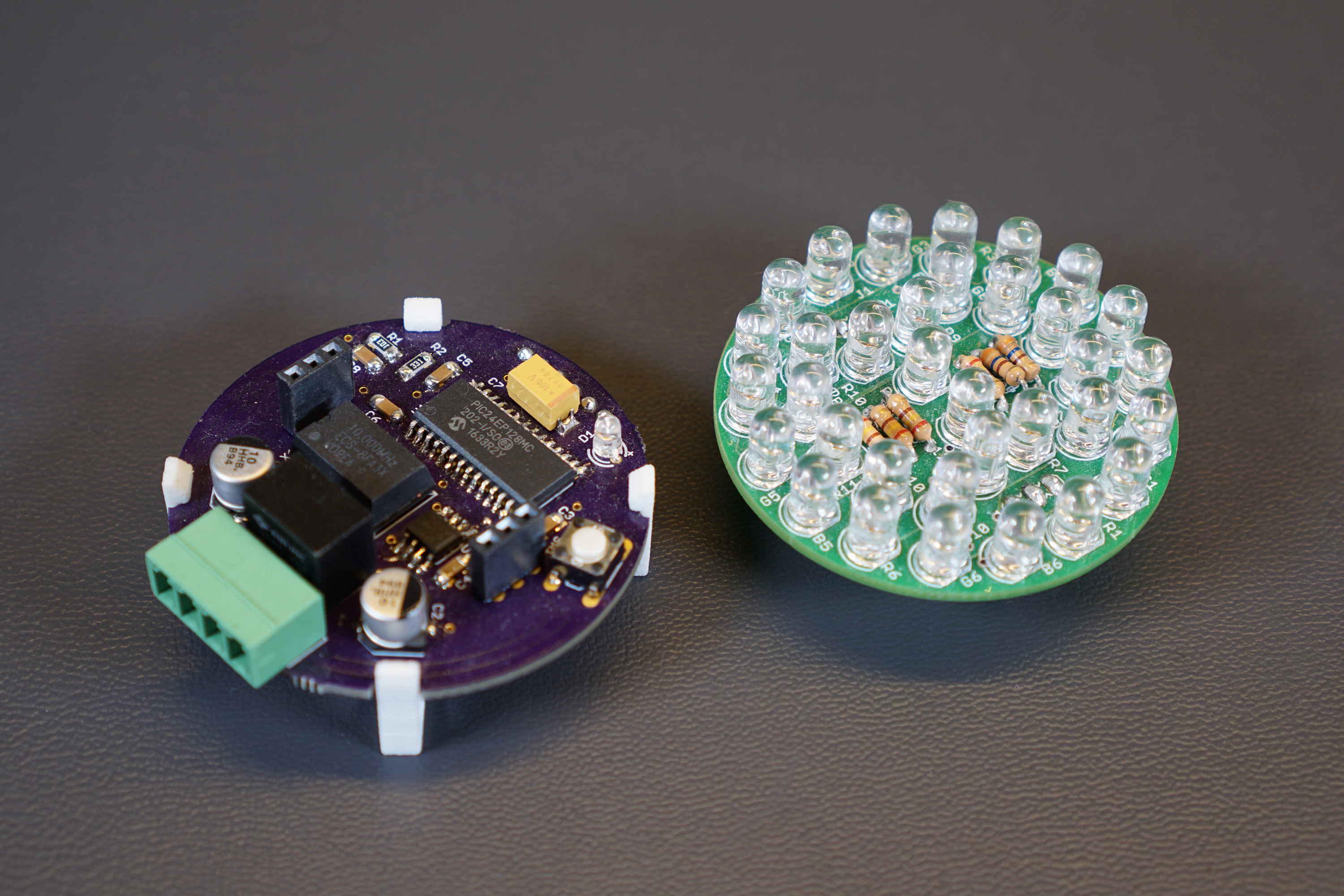
The next iteration was a 2″ round version of the six inch strip light. The electronics were placed on one board, the LEDs were placed on a second board, and the two boards connected together using some header strips and header pins. The electronics board contained slots that snapped into a mounting bracket. This permitted the board to lay flat or be taped or screwed in place. There were still some minor annoyances like not having a case, the power supply hit the bottom of the LED board, and the oscillator and low ESR caps are huge.
Round v2
That brings us to the latest version of the RGB LED lamp. The basic requirements were:
- The lamp is completely enclosed.
- The lamp uses a low-profile switching power supply.
- The lamp uses a small oscillator.
- The lamp uses a small and inexpensive low-ESR cap for the PIC24.
Other than the above, I liked the round form factor, software, and basic functionality of the first round version.
Hardware Design
This board has a lot of experiments including a MEMS oscillator, a custom switching power supply, and a new low-ESR capacitor for the PIC24’s Vcap pin.
This design had lots of new things to try out: a new power supply, a new oscillator, a new capacitor, and a new enclosure with an overlapping lip designed to compensate for tolerances in the vertical stack up of the assembly.
Selecting a PIC24 Variant
Picking a PIC24 was easy. The design would use the same PIC24EP128MC202 that the previous three iterations used. Below is a schematic showing the basic connections for the PIC24. To this basic schematic, we’ll add a switching power supply, a 10 MHz MEMS oscillator, DMX transmit and receive capability, and some transistor switches that control the LEDs.
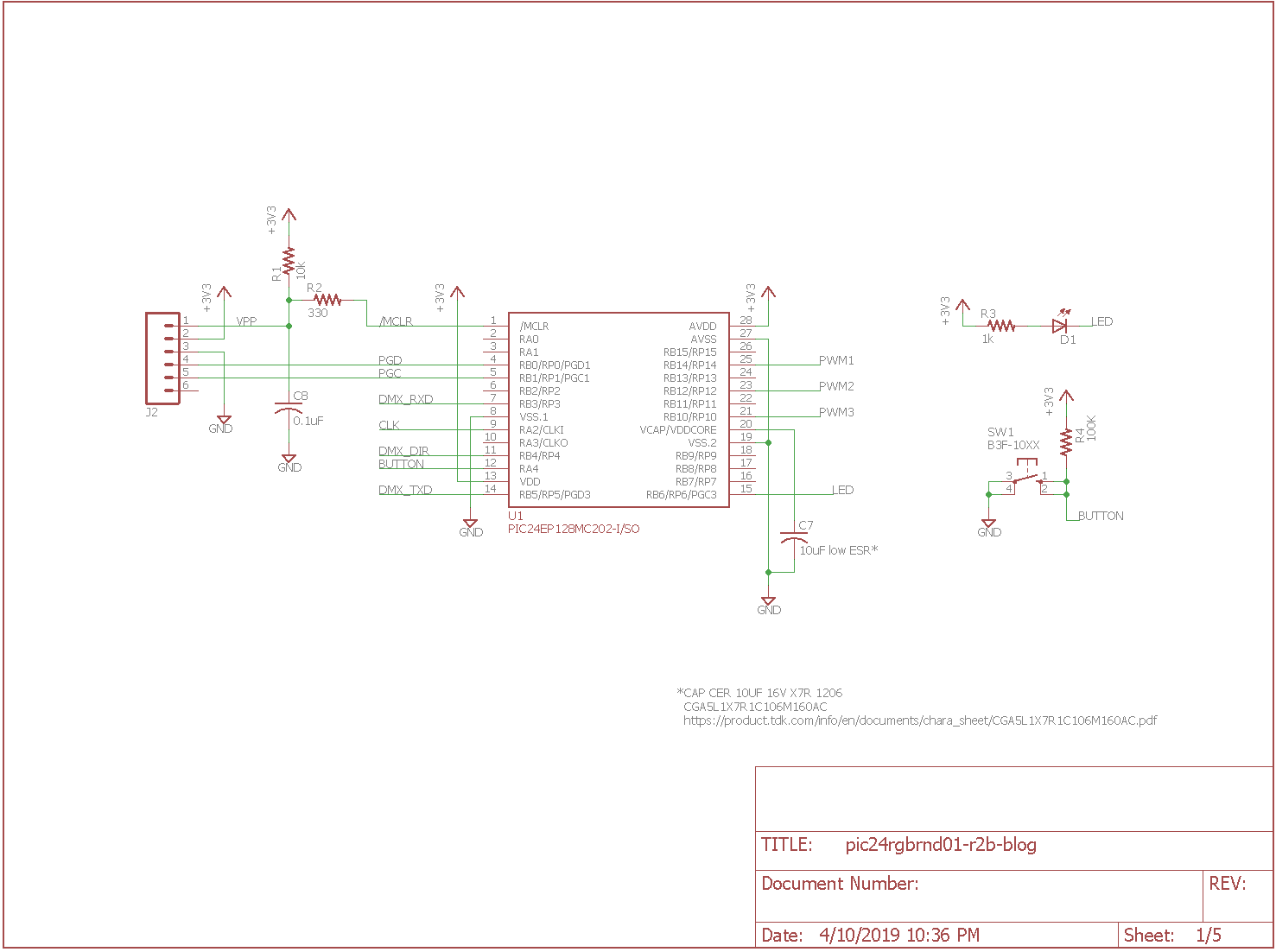
Basic PIC24 connections.
Low ESR Cap Selection
One of the goals for this project was to use a smaller and less expensive low-ESR cap on the PIC24’s VCAP/VDDCORE pin. Here’s the requirements according to the PIC24EP128MC202 data sheet:
A low-ESR (< 1 Ohm) capacitor is required on the VCAP pin, which is used to stabilize the voltage regulator output voltage. The VCAP pin must not be connected to VDD and must have a capacitor greater than 4.7 μF (10 μF is recommended), 16V connected to ground. The type can be ceramic or tantalum.
After perusing capacitor data sheets for over an hour, I finally settled on a TDK part that had < 1 Ohm ESR at all frequencies between 10kHz and 100MHz. The TDK CGA5L1X7R1C106M160AC capacitor is a 10uF +/- 20% ceramic capacitor with an X7R temperature characteristic, a rating of 16V, a 1206 package, and best of all, a price of about fifty cents in small quantities. The previous low ESR cap was huge and over three dollars.
TI Simple Switcher Buck Converter
Another goal for this project was to use a lower-profile switching power supply capable of stepping the input +24V power supply voltage down to +3.3V for the PIC24 microcontroller and other digital logic. I had been using a Cui V7803-500 high-efficiency switching drop-in linear regulator replacement on the previous designs. This part is very tall and causes interference when mating the LED board to the logic board. I needed something shorter.
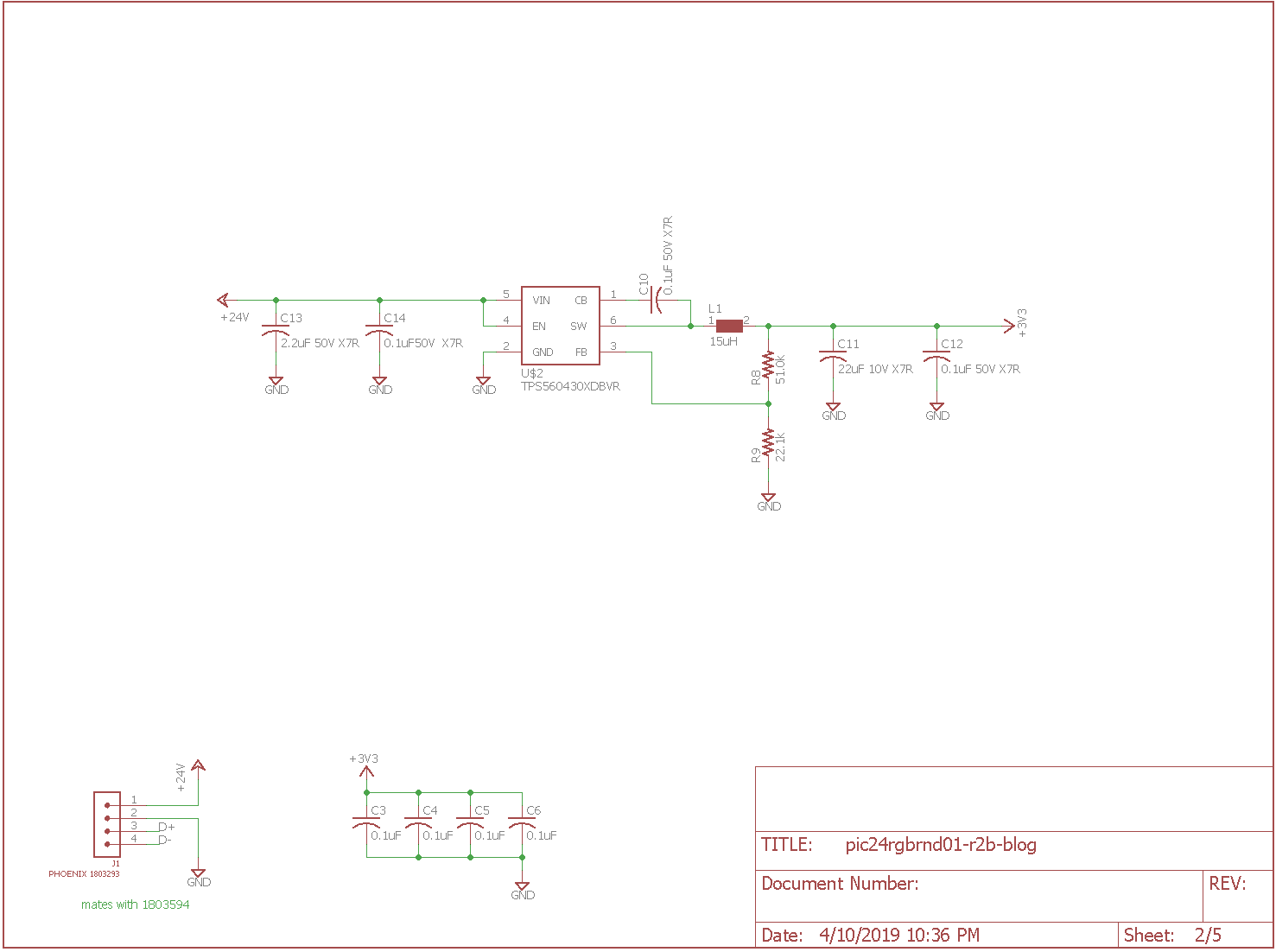
TI Simple Switcher schematic.
TI has a series of high input voltage step down switching regulators called TI Simple Switchers. These are easy to use and require minimum external support components. I selected one of these then used their reference design schematic and PCB layout to recreate the circuit and layout on my project.
The schematic for the switching power supply is shown in the schematic above. Also on this schematic page are decoupling capacitors for all the digital circuitry and the power / data input connector. This power supply circuit has plenty of vertical clearance. Unfortunately as built, it occupies more board real estate than the CUI device.
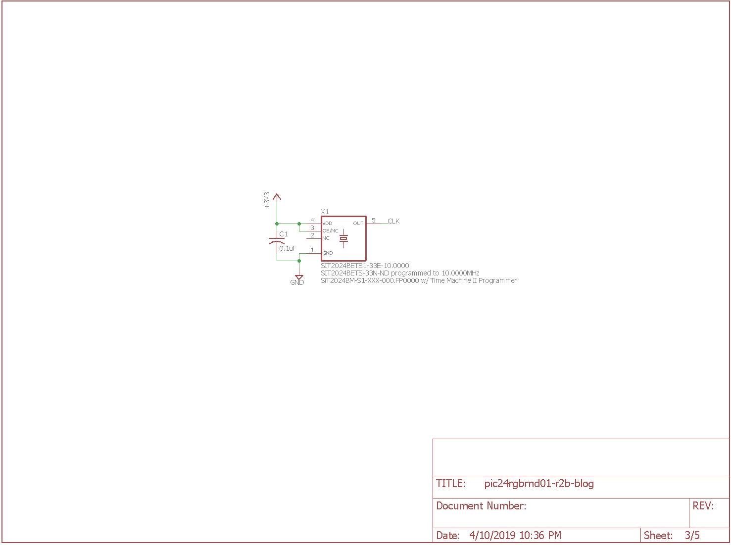
SiTime MEMS Oscillator
To make room for the new switching power supply, I needed a smaller oscillator. Most small crystal oscillators are in leadless packages that are hard to solder. While I was working on this project, news broke about high helium atmospheres crashing iPhones. The root cause was helium penetrating the MEMS oscillator used in the iPhone and changing the oscillator’s frequency. I did a bit more research and discovered a company called SiTime that makes a wide range of MEMS oscillators.
Digging further, they had a 3.3V version in a tiny, easy-to-solder SOT23-5 package that could be programmed to run at 10MHz. Even better, Digi-Key sells them and will program them to your requested frequency. The exact manufacturer part number is SIT2024BETS-33N and the Digi-Key part number is SIT2024BETS-33N-ND. Just add one to your cart and specify the programming frequency in the order notes. As shown in the schematic below, they’re pretty easy to use too. Just add a decoupling capacitor and tie the output enable pin high.
Receiving DMX
The hardware for transmitting and receiving the DMX protocol is remarkably simple. If you want to spend a lot of money you can use isolated RS-485 transceivers. I’d already spent enough on this project so I used a TI SN65HVD11D as shown in the schematic below. Hook up the D- and D+ lines to the DMX connector. Hook up the data in, data out, and direction lines to the microcontroller. At some point, I need to figure out an ESD protection circuit for the DMX D+ and D- signals.
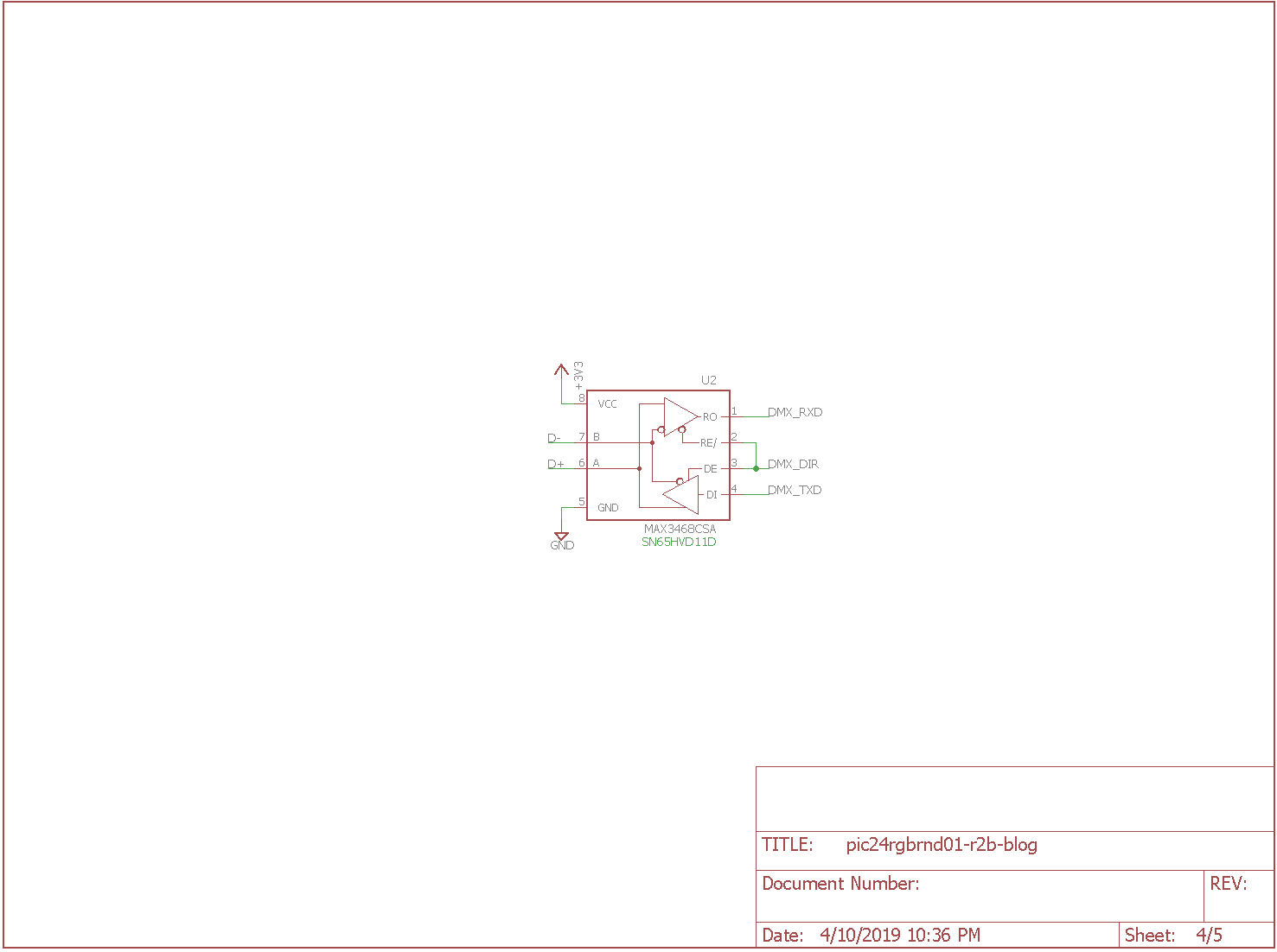
DMX transmit / receive circuitry. This could use some ESD protection in a future version.
Transistor Switches
I’ve been using FMMT619TA NPN BJT transistors to switch the strings of RGB LEDs on and off for what feels like forever now. There was no reason to change now. These are in a tiny SOT-23 package. They’re rated for 2A. They can easily switch on and off the 40mA of LED strings without getting hot or requiring heat sinks. A 1k resistor connected between each of the PIC’s PWM outputs and each transistor’s base limits the base current to prevent destruction of the transistor while also supplying enough base current to drive the transistor into its saturation region.
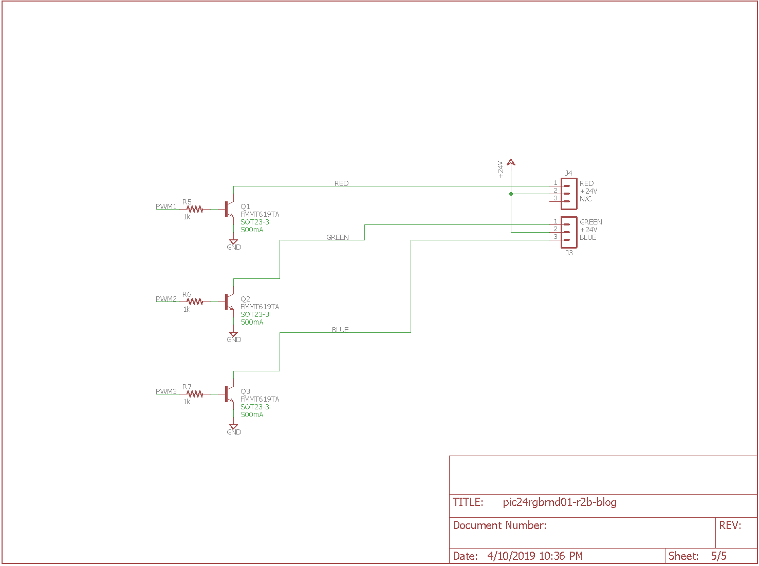
NPN BJT transistors used to switch the LEDs on and off.
Completed Schematic
Below is the completed schematic for the RGB lamp’s controller board.
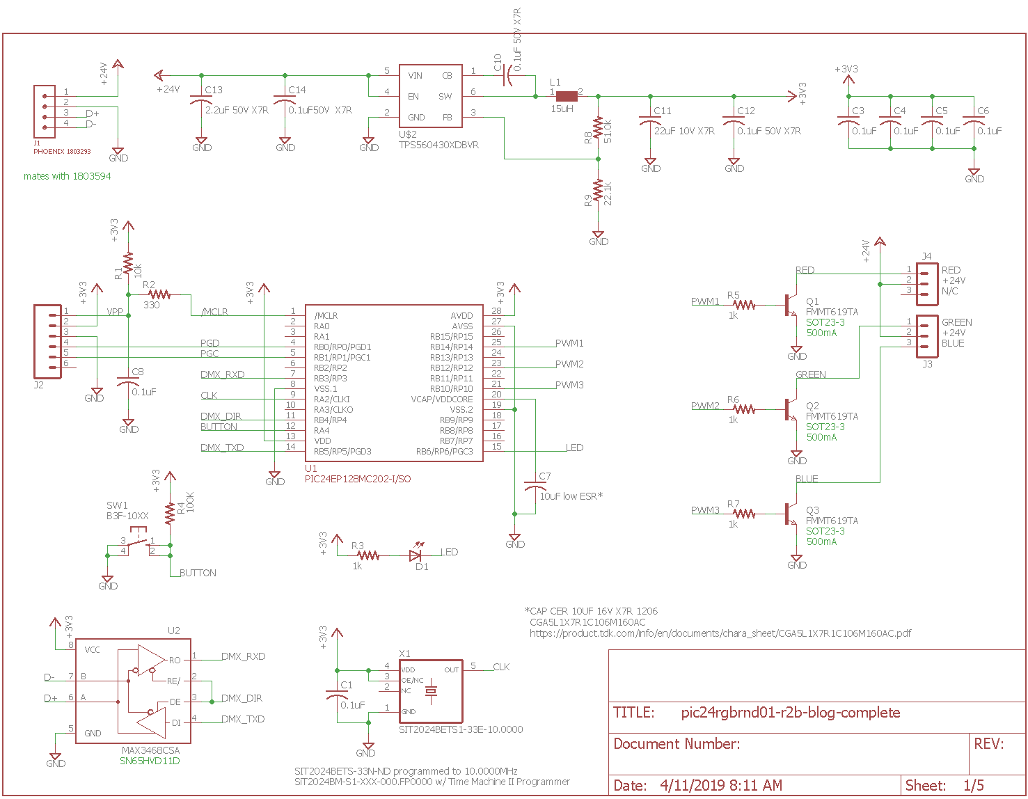
Completed schematic.
Board Layout
Now that the schematic was complete, it was time to move on to the board layout. I drew the initial board outline as a sketch in Fusion 360. I exported the sketch as a DXF file then imported the DXF file on to layer 20, the dimension layer, in Eagle PCB. A few of the arcs and lines had to be touched up by hand to get the board outline to be a completely closed shape.
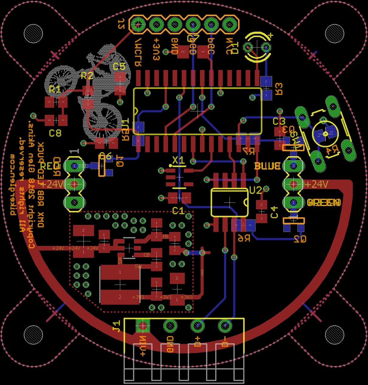
Completed board layout.
Components are arranged similarly to how they are on the first version of the round PCB RGB LED lamp. The power supply layout is copied from the TI Simple Switcher evaluation board. The power transistors that switch the LEDs on and off are on the back of the board. The top layer includes a +3.3V power fill. The bottom layer includes a ground fill. A second ground fill was included on the top layer directly underneath the switching power supply. This ground fill is heavily coupled to the bottom layer ground fill using tons of vias.
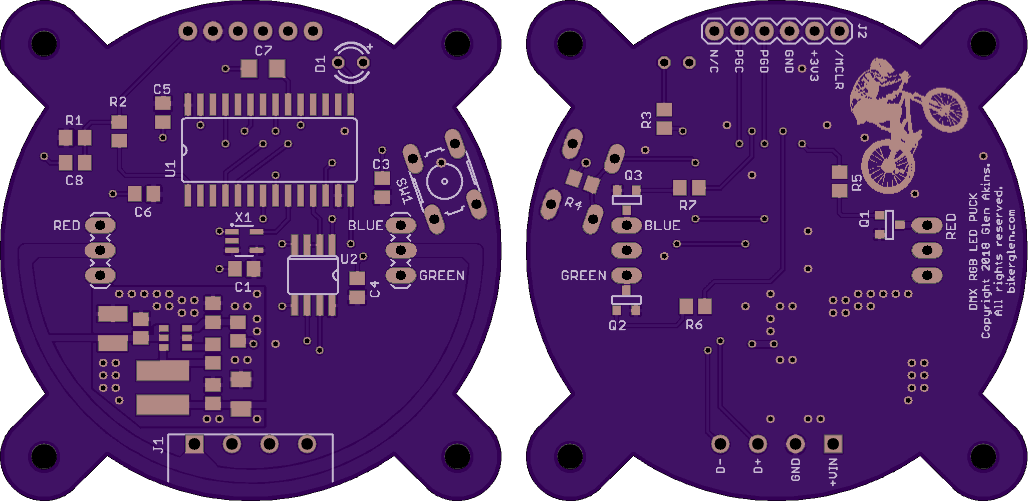
Oshpark board renders.
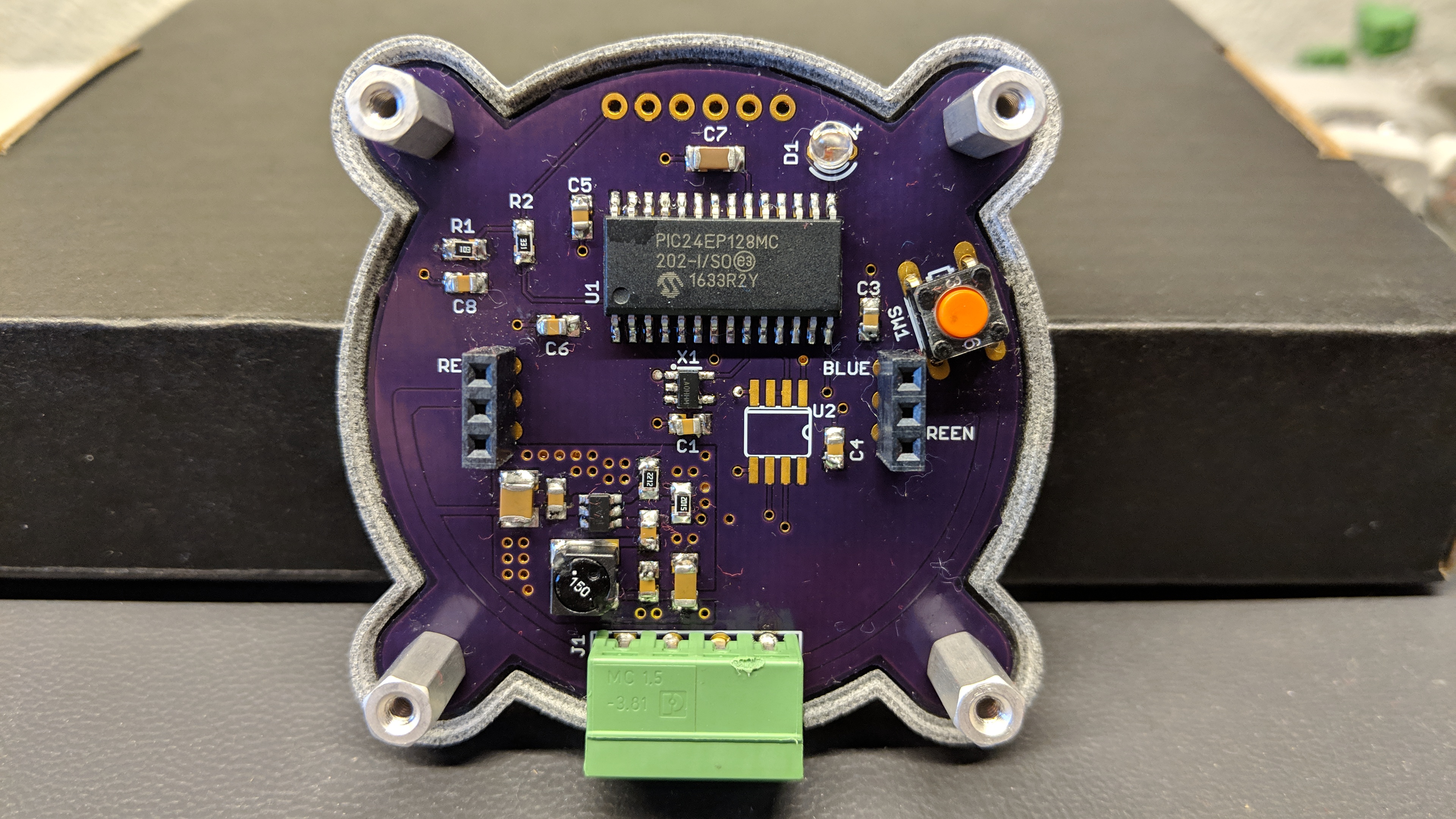
The final step in the board design process was to upload the board’s gerber files to Oshpark and check the renders for any final mistakes. This is where problems with the silk screen like incorrectly mirrored or overlapping text become apparent. Finally I ordered boards and assembled them when they arrived. Below is a photo of both sides of the assembled board.
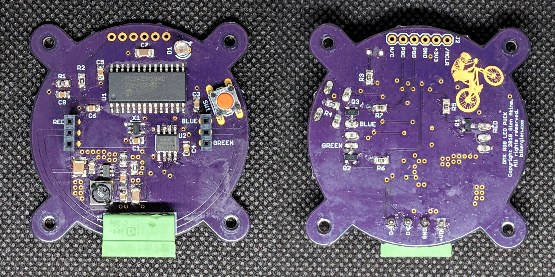
The completed board. Probably should get some isopropyl alchohol and clean it up a better sometime.
The LED Board
The LED board was simple in comparison to the controller board. It’s just a bunch of through hole LEDs, resistors, and terminal strips. The LEDs are arranged in a pair of red LED strings, a pair of green LED strings, and a pair of blue LED strings. Each red string uses 7 LEDs and each green and blue string use 5 LEDs. The resistors were chosen to limit the current to each string of LEDs to 15 mA.
Here’s the schematic. I have no idea if those CREE part numbers are good or not anymore. They’re several years old. I used LEDs from my parts stock. Sometime I’ll have to look up the exact part number I used and add them to this post.
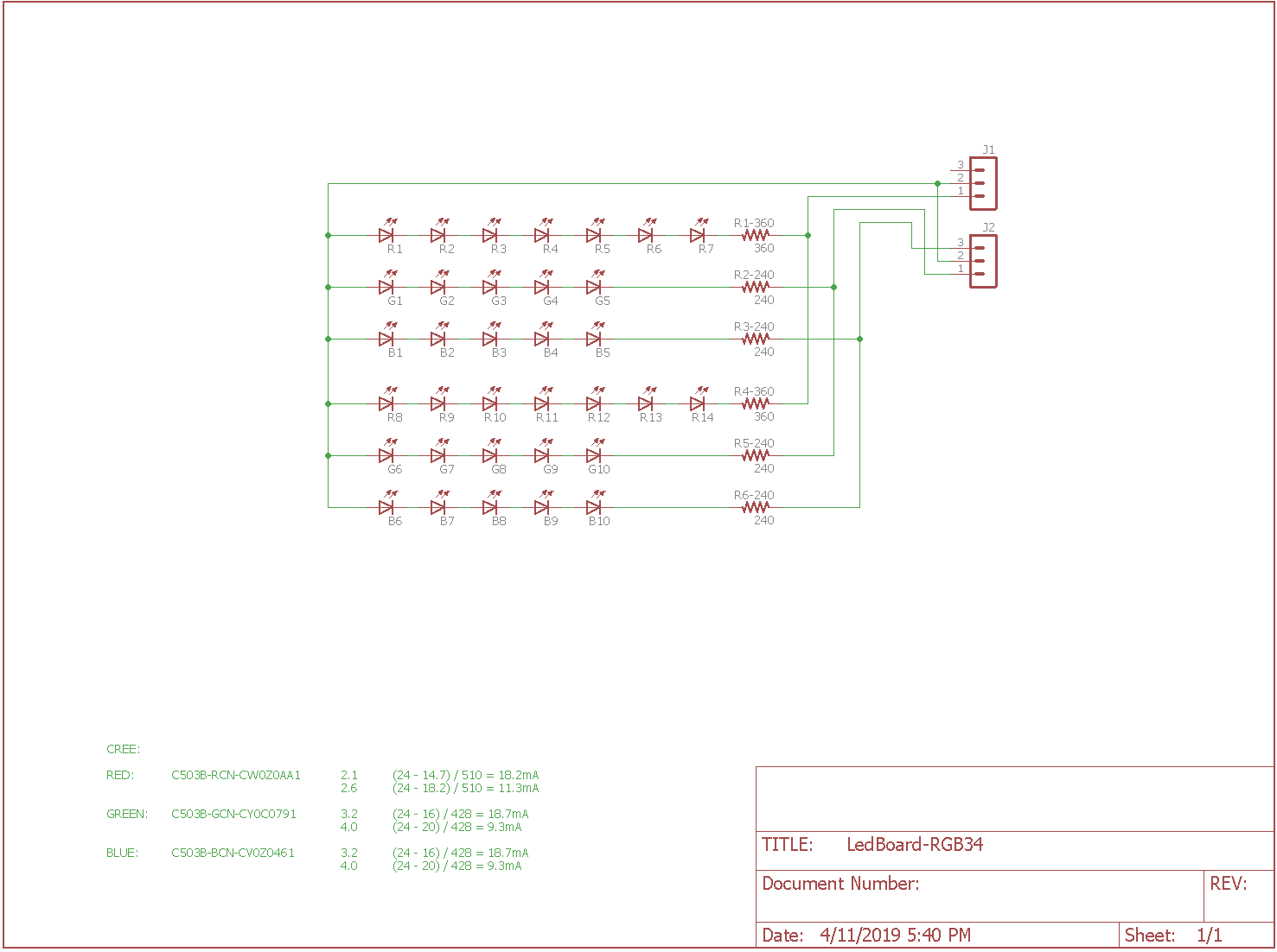
Led board schematic.
Here’s the Oshpark render:
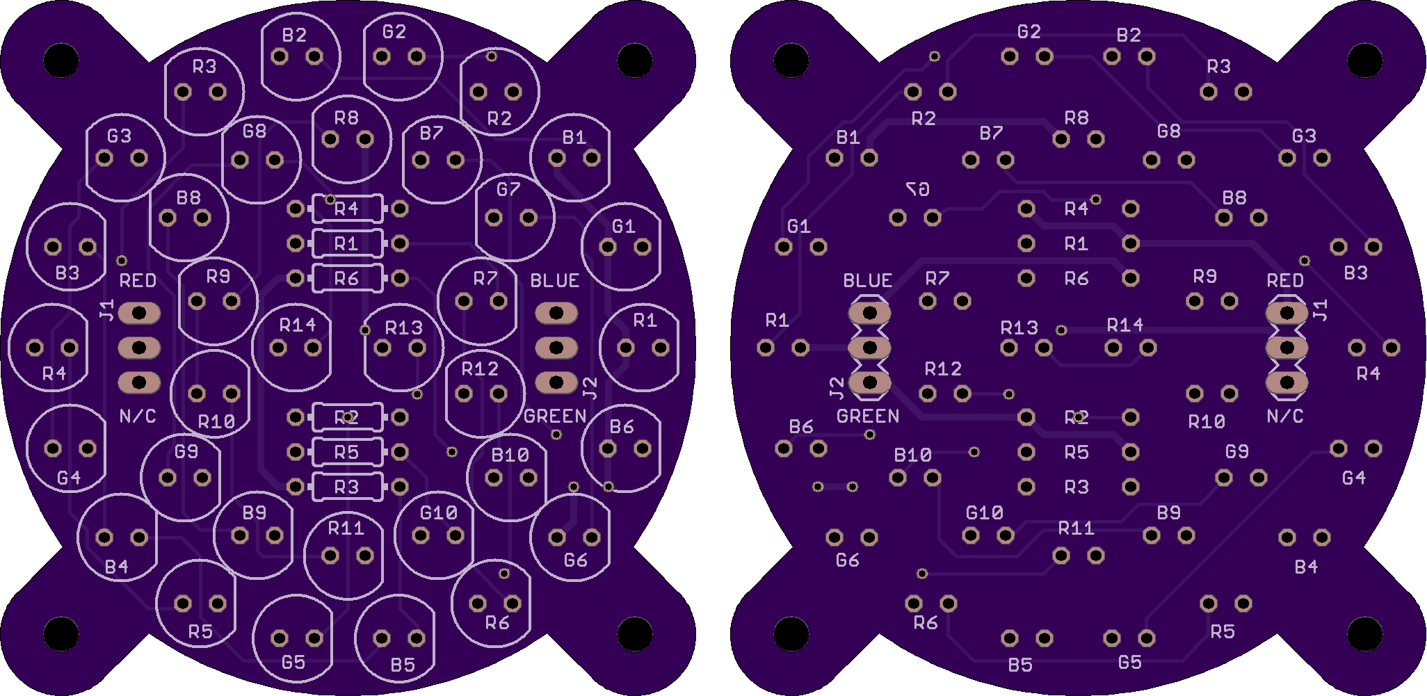
Oshpark render of the LED board.
And here’s a photo of both sides of the assembled LED board.
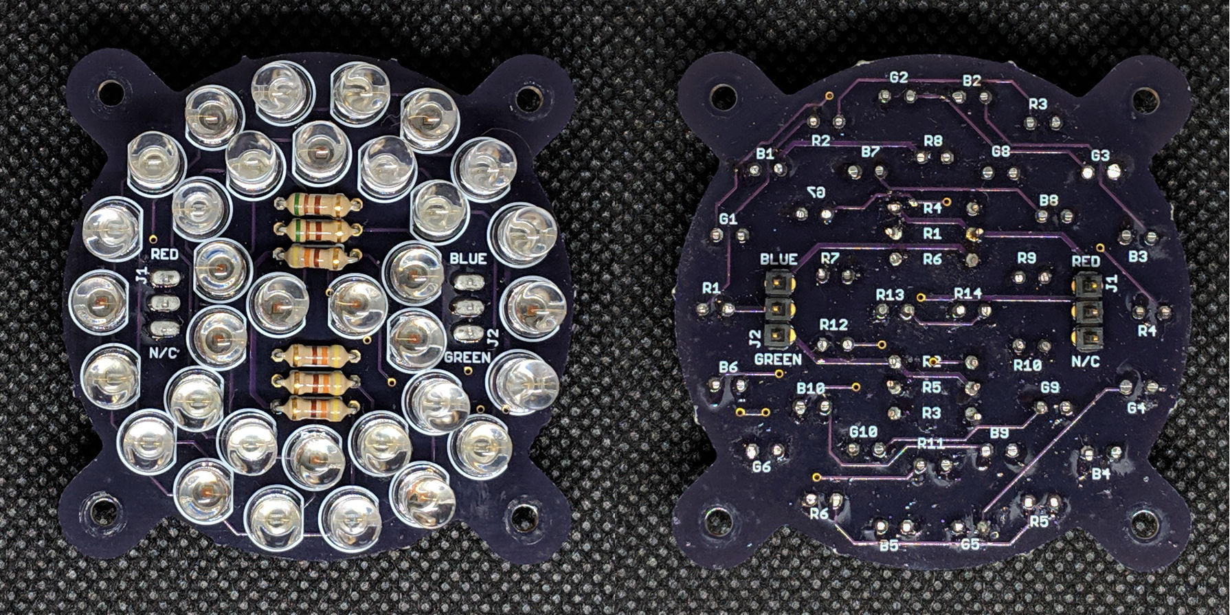
The assembled LED board. Guess which LEDs are red.
Mechanical Design

This build had two circuit boards, a 3D printed enclosure, a laser cut acrylic lid, and numerous screws and standoffs that all had to come together and function as a single unit.
This build was one of my more complicated mechanical designs as well. The enclosure needed to hold two circuit boards and a lens. It also had to have a cutout for the power / data connector. The vertical stackup had lots of tolerances yet the enclosure still needed to fit together tightly regardless of the actual dimensions of the parts used. I also planned on using a relatively new 3D printing process and material.
Material
Most of my 3D printing experience is with nylon printed on Electro Optical System’s line of selective laser sintering (SLS) printers. Around the time of this project, HP released their line of HP Multi Jet Fusion 3D printers. The service bureau I normally use for 3D prints, Sculpteo, was making a big push to popularize HP’s Jet Fusion process and get users to try out the new material. I figured I’d give it a try.
Sculpteo has a comparison of the EOS’s SLS and the HP Jet Fusion technology. The design rules for both printers are very similar and I don’t tend to push the design rules with either technology. This means that what I print on one printer will usually print on the other printer without issues. Generally, the thinnest printable feature is 0.7mm thick and a thickness of 1.5mm to 2.0mm works well for walls.
The biggest differences between the two printers for me are the accuracy of the parts, the stiffness of the material, and the color options. The Jet Fusion prints have better accuracy and are slightly stiffer / less flexible than the EOS SLS parts.
Two project enclosures printed on HP Jet Fusion 3D printers. One is the raw finish. The other is dyed black.
On the downside, Jet Fusion prints have less finishing options than EOS SLS parts. The EOS SLS PA12 nylon is white. This permits finished parts to be dyed just about any color. The Jet Fusion nylon is a dark gray. The only real color options are the raw dark gray, which is what I used on this project, and dyed black. Above is a photo of two different projects in the raw finish and the dyed black finish.
Enclosure Bottom
The enclosure bottom was designed to hold the PCB by the four tabs extending out from the central circular part of the board. These tabs fit in four recesses in the enclosure bottom and hold the board TODO mm above bottom of the enclosure. This allows room for small surface mount components like resistors, capacitors, and SOT23 transistors to be mounted on the bottom of the board.
The cavities that hold the tabs and board are 1.65mm deep to hold the 1.6mm thick board. The clearance between the board and all edges of the interior of the enclosure is 0.5mm. On the underside of the enclosure are four recesses to hold 2-56 pan head hex drive screws.
Here’s a render of the bottom half of the enclosure as viewed from the top:

Render of the bottom half of the enclosure as viewed from the top.
Here’s a render of the bottom half of the enclosure as viewed from the bottom:
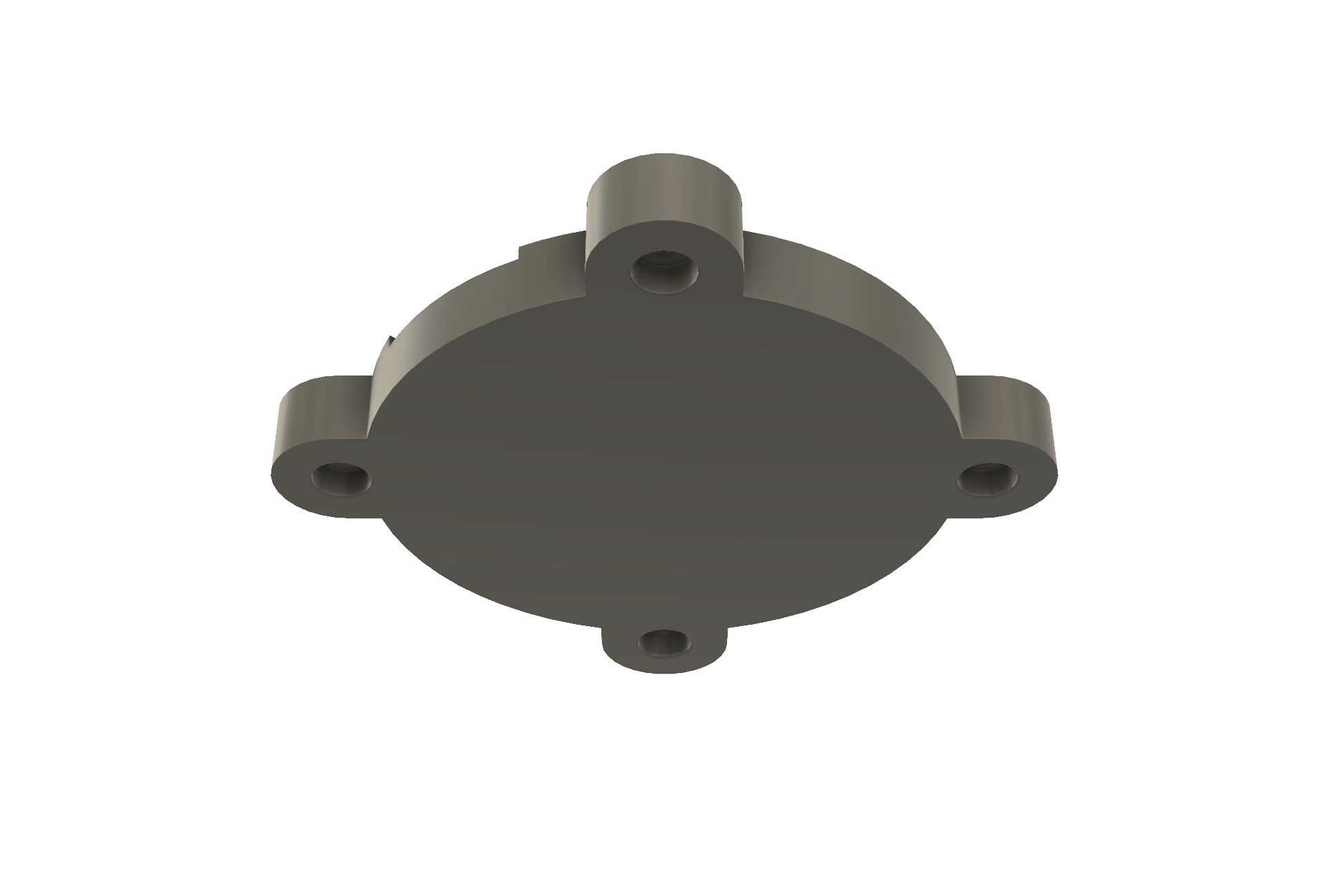
Render of the bottom half of the enclosure as viewed from the bottom.
Enclosure Top
The enclosure top rests on the enclosure bottom and hold the circuit board in place. It is tall enough to hold both boards with some clearance between the top of the LEDs and the bottom of the lid. Here’s a render of the top half of the enclosure as viewed from the top:
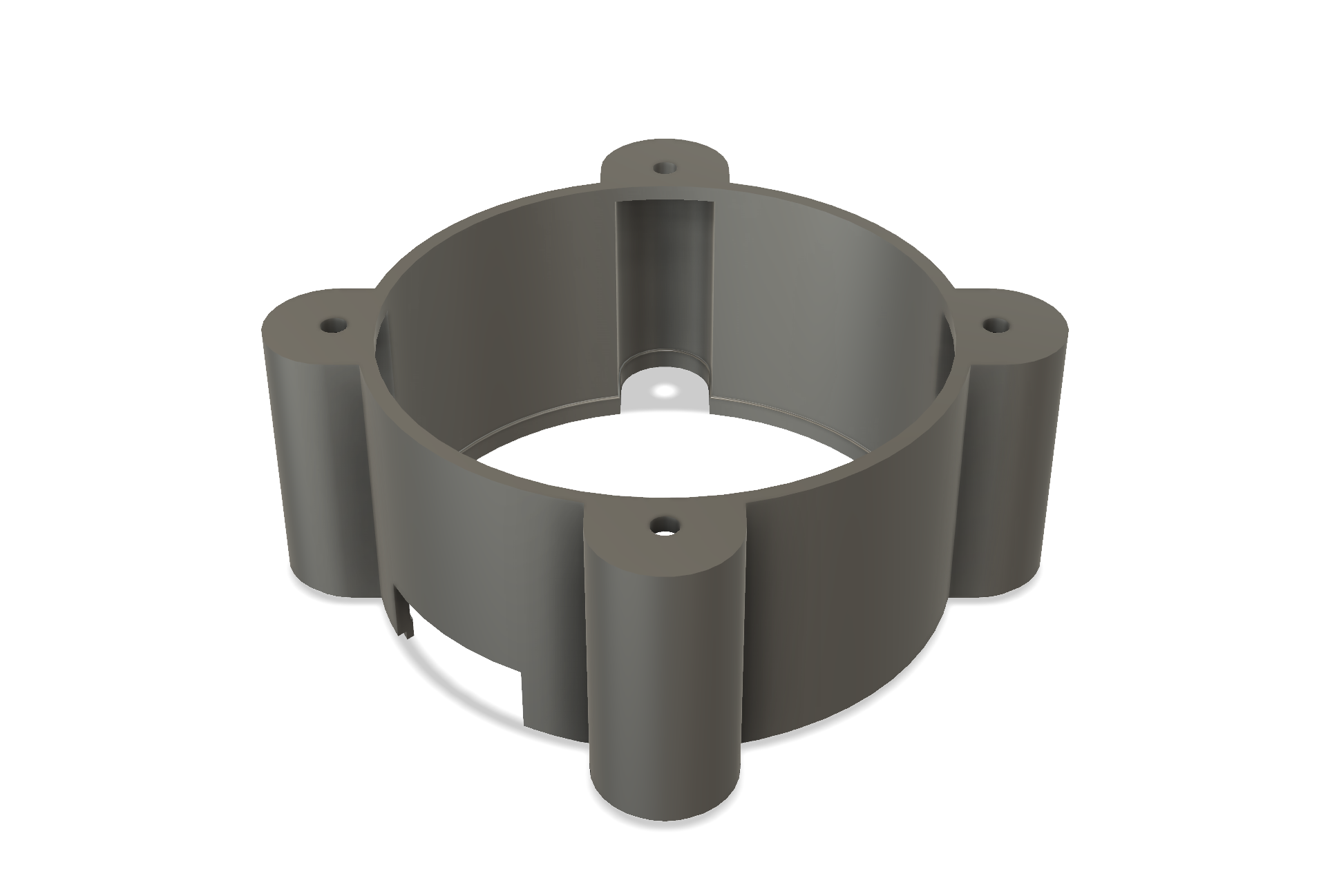
Render of the top half of the enclosure as viewed from the top.
Here’s a render of the top half of the enclosure as viewed from the bottom:
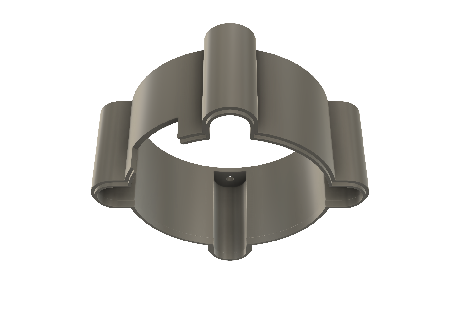
Render of the top half of the enclosure as viewed from the bottom.
Connector Cutout
To create the cutout for the connector, I used the Fusion 360 construction, sketch, and extrude commands. The first step was to use the construction tools to create four planes each offset from the sides of the connector by 0.25mm. The photo below shows the constructed planes:

Construction planes offset 0.25mm from the outside surfaces of the connector.
The next step was to create a new sketch on the bottom plane. This rectangle needed to be sized to cut away the portions of the enclosure around the connector. The left edge was at the left plane. The right edge was at the right plane. The front extended just beyond the enclosure front. The rear extended just beyond the inside wall of the enclosure.
Once the rectangle was sketched, I exited the sketch and used the extrude command to cut both halves of the enclosure. The extrusion height ran from the bottom plane to the top plane and the mode was set to cut:
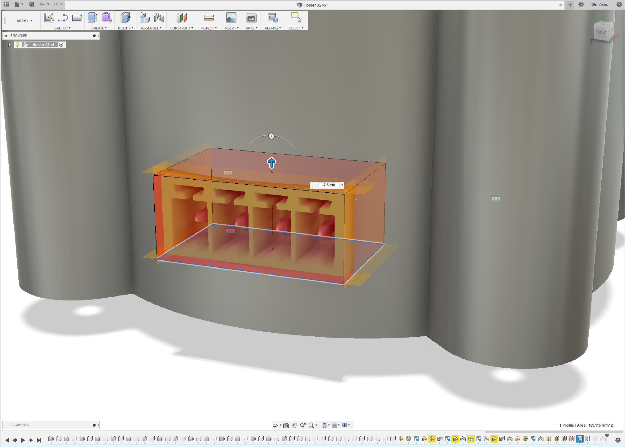
The extrude and cut operation.
This left me with a hole perfectly sized for the power / data connector.
Compensating for Vertical Tolerances
The vertical stackup has a lot of different components with varying tolerances. A solution was needed to ensure the enclosure halves fit together snug regardless of the individual component tolerances. The solution was to create overlapping lips on each half of the enclosure. If the vertical stackup came up short, the enclosure halves would rest on each other. If the vertical stackup came up tall, the lip would still fill the gap between the enclosure halves even if they didn’t directly rest on each other. Circled in red below is the lip that runs all the way around both halves of the enclosure.
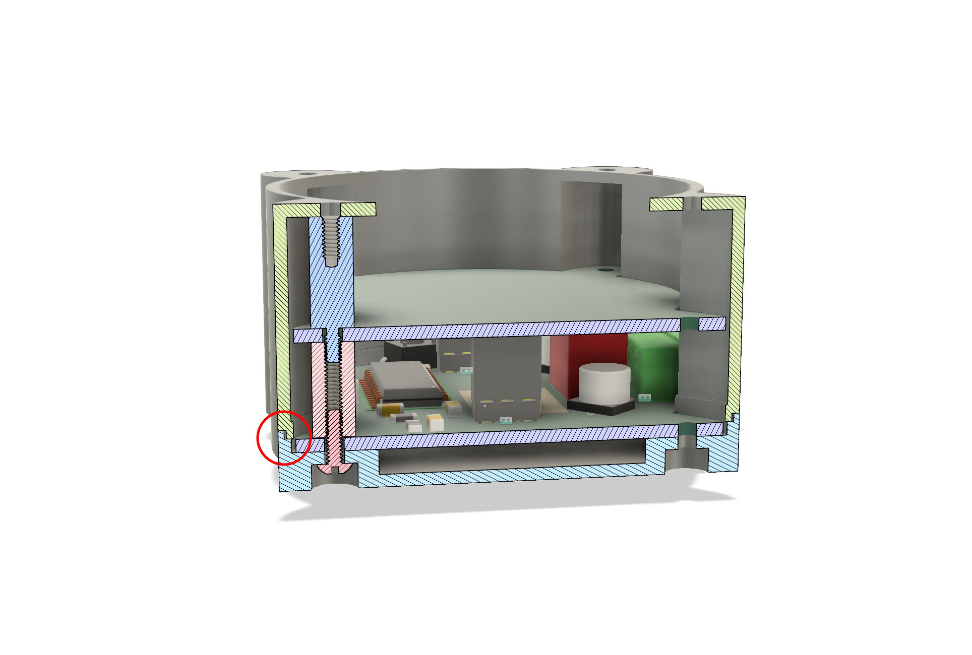
Circled in red is the lip that runs all the way around both halves of the enclosure.
On the bottom half of the enclosure, the lip wall is 0.7mm thick and runs along the outside surface of the enclosure. It’s 1mm tall. On the top half of the enclosure, the lip is 0.8mm thick and extends 0.25mm into the inside of the enclosure. The clearance between the two lip walls when assembled is 0.25mm. On the top half of the enclosure, the overall lip height is 2mm. That is divided into two portions each with a height of 1mm. The lower portion mates with the lip on the bottom half of the enclosure. The upper portion is there to meet the minimum wall thickness requirements for the 3D printing process.
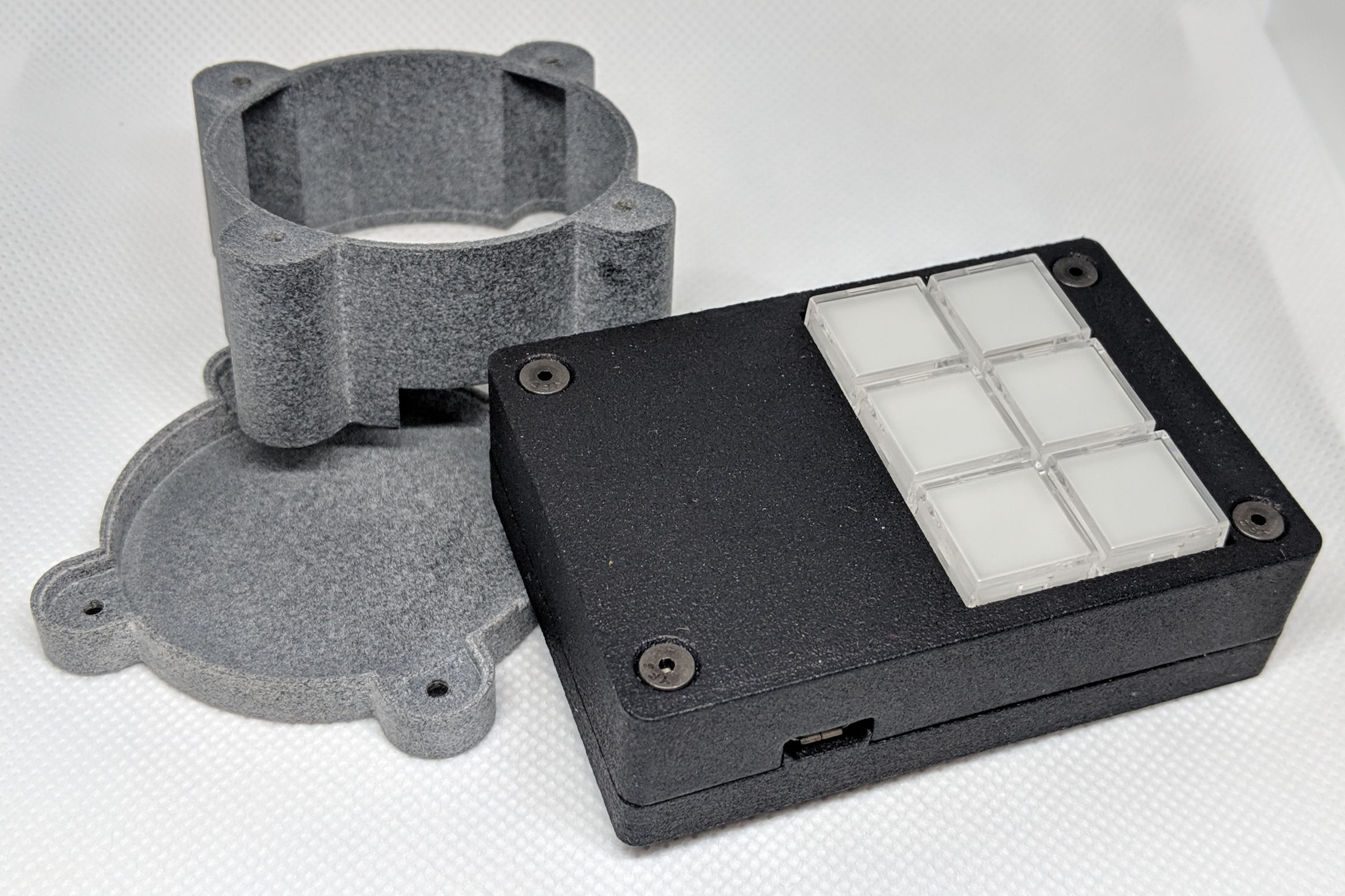
The photo below shows the overall stackup of the components inside the light fixture. You can see the lip on the two enclosure halves too.
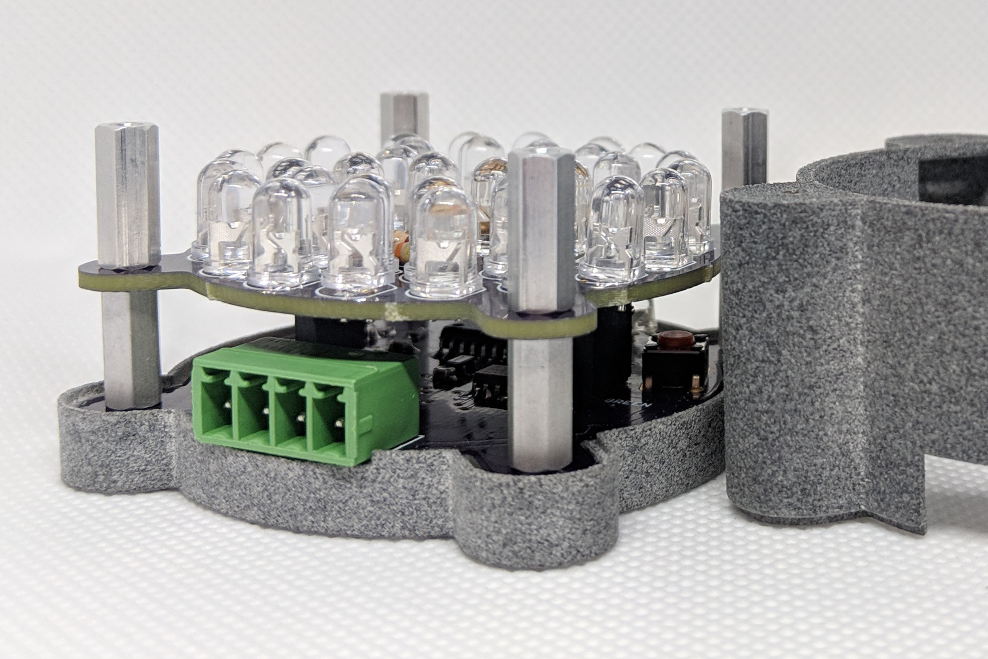
If you look closely, you can see the overlapping lips on each half of the enclosure in this photo.
Laser Cutting the Lid
The final mechanical part of the project was to laser cut a lid for the enclosure out of clear acrylic. The laser cutting service requires a DXF file with the outline to cut. To generate a DXF file to cut, I created a sketch on the top of the enclosure then used the sketch project command to project the geometry of the top of the enclosure into the sketch. Once that was completed, I right clicked on the sketch in the design browser and selected export DXF. I uploaded the DXF file to the laser cutting service and received a laser cut acrylic lid for the project about a week later.
Software
Setting the Config Bits
One of the more painful steps when using a new PIC microcontroller for the first time is determining the correct values for the processor’s config bits. These bits are programmed alongside the firmware. The usually control the clock source for the processor and the functionality of some I/O pins. When they’re wrong, things don’t work as expected. Errors in the config bits can result in your PIC running at half speed, one-fourth speed, or hilariously, 32kHz instead of 32MHz. Here’s the values of the config bits I used on this project:
// FICD
#pragma config ICS = PGD3
#pragma config JTAGEN = OFF

// FOSCSEL
#pragma config FNOSC    = FRC
#pragma config PWMLOCK  = OFF
#pragma config IESO     = OFF

// FOSC
#pragma config POSCMD   = EC
#pragma config OSCIOFNC = OFF
#pragma config IOL1WAY  = OFF
#pragma config FCKSM    = CSECMD

// FWDT
#pragma config PLLKEN   = ON
#pragma config WINDIS   = OFF
#pragma config FWDTEN   = OFF
The FICD config bits control debugging. In this case, the in-circuit debugging is placed on the PGD3 pins and JTAG is disabled. The FOSCSEL bits select the internal RC oscillator. The internal RC oscillator will be used at power up until the PLL is configured and locked to the external SiTime MEMS oscillator.
The FOSC bits select an external oscillator on the clock input, set the OSC2 pin as a general purpose IO, enable clock switching, and enable multiple reconfigurations of the peripheral pin select module. Clock switching must be enabled to switch from the internal RC oscillator to the PLL clock output later in software. The PPS select allow the external IO pins on the PIC24 to be assigned to different peripherals inside the PIC24. If you’re designing a brushless motor controller or antilock brake system where malfunctions could be destructive, setting the IOL1WAY bit to ON would be a good idea to prevent errant software glitches from reconfiguring the IO pins. In our case, multiple reconfigurations are fine.
The final group of bits are the FWDT watchdog timer bits. We enable PLL lock detection but disable the watchdog timer. Again, if you’re designing a brushless motor controller or antilock brake system where malfunctions could be destructive, enabling the watchdog timer might be a good idea.
Clock Switchover
Based on the configuration bits, our PIC24 boots with the internal RC oscillator as the clock source for the CPU. The PIC24 is capable of running much faster than that though by locking its internal PLL to an external clock source and running from the PLL clock output. Here’s the code to do that:
    // Configure PLL prescaler, PLL postscaler, PLL divisor
    // with 10MHz external clock
    // Fin   = 10MHz
    // Fplli = Fin/N1  = 10/2  = 5MHz     0.8 < Fplli < 8.0
    // Fsys  = Fplli*M = 5*32  = 160MHz   120 < Fsys  < 340
    // Fosc  = Fsys/N2 = 160/2 = 80MHz    15  < Fosc  < 120
    // Fcy   = Fosc/2  = 80/2  = 40MHz
    PLLFBD             = 30; // PLLFBD  = M-2  = 32-2 = 30
    CLKDIVbits.PLLPOST =  0; // N2 = 2 => PLLPOST = 0
    CLKDIVbits.PLLPRE  =  0; // N1 = 2 => PLLPRE  = 0

    // Initiate Clock Switch to Primary Oscillator with PLL (NOSC=0b011)
    __builtin_write_OSCCONH(0x03);
    __builtin_write_OSCCONL(OSCCON | 0x01);

    // Wait for Clock switch to occur
    while (OSCCONbits.COSC!= 0b011);

    //  Wait for PLL to lock
    while (OSCCONbits.LOCK!= 1);
The code above boots using the internal RC oscillator and enables the PLL. We then switch immediately to using the clock output from the PLL. Once the PLL is locked to the external SiTime MEMS oscillator, we boot into the main portion of our code. The result is that our PIC24 is now running at its maximum rated speed.
Using the PWM Peripheral
The following initialization code configures the PWM peripheral to run at a PWM frequency of 1220.7 Hz (1220.7 Hz is the 80 MHz Fosc divided by 65536):
    // initialize PWM
    PTCONbits.EIPU = 1;
    PTCON2bits.PCLKDIV = 0b000;
    PTPER = 65535;

    PHASE1 = PHASE2 = PHASE3 = 0;
    PDC1 = PDC2 = PDC3 = 0x100;
    DTR1 = DTR2 = DTR3 = 0;
    ALTDTR1 = ALTDTR2 = ALTDTR3 = 0;
    IOCON1 = IOCON2 = IOCON3 = 0xC000;
    PWMCON1 = PWMCON2 = PWMCON3 = 0x0000;
    FCLCON1 = FCLCON2 = FCLCON3 = 0x0003;

    PTCONbits.PTEN = 1;
The following code is then used to update the PWM peripheral with new red, green, and blue values:
PDC1 = PMapLut[rx_data[0]];
PDC2 = PMapLut[rx_data[1]];
PDC3 = PMapLut[rx_data[2]];
The PWM peripheral has 16-bit resolution so I also needed a new gamma table to take advantage of the increased resolution. The PMapLut array holds the gamma correction table. Here’s the most recent version of my gamma table:
static const unsigned short PMapLut[256] = {
       0,    63,  127,  191,  191,  255,  255,  319,  319,  383,  447,  447,  511,  511,  575,  639,
      703,  703,  767,  831,  895,  895,  959, 1023, 1087, 1151, 1151, 1215, 1279, 1343, 1407, 1471,
     1535, 1599, 1663, 1727, 1791, 1855, 1919, 1983, 2047, 2111, 2239, 2303, 2367, 2431, 2495, 2623,
     2687, 2751, 2815, 2943, 3007, 3135, 3199, 3263, 3391, 3455, 3583, 3647, 3775, 3839, 3967, 4031,
     4159, 4287, 4351, 4479, 4607, 4735, 4799, 4927, 5055, 5183, 5311, 5439, 5567, 5631, 5759, 5887,
     6015, 6207, 6335, 6463, 6591, 6719, 6847, 6975, 7167, 7295, 7423, 7615, 7743, 7871, 8063, 8191,
     8383, 8511, 8703, 8831, 9023, 9151, 9343, 9535, 9727, 9855,10047,10239,10431,10623,10751,10943,
    11135,11327,11519,11775,11967,12159,12351,12543,12735,12991,13183,13375,13631,13823,14079,14271,
    14527,14719,14975,15167,15423,15679,15871,16127,16383,16639,16895,17151,17407,17663,17919,18175,
    18431,18687,18943,19199,19519,19775,20031,20351,20607,20863,21183,21503,21759,22079,22335,22655,
    22975,23295,23551,23871,24191,24511,24831,25151,25471,25791,26175,26495,26815,27135,27519,27839,
    28223,28543,28927,29247,29631,29951,30335,30719,31103,31423,31807,32191,32575,32959,33343,33727,
    34175,34559,34943,35327,35775,36159,36607,36991,37439,37823,38271,38719,39103,39551,39999,40447,
    40895,41343,41791,42239,42687,43135,43647,44095,44543,45055,45503,46015,46463,46975,47423,47935,
    48447,48959,49471,49983,50495,51007,51519,52031,52543,53055,53631,54143,54655,55231,55743,56319,
    56895,57407,57983,58559,59135,59711,60287,60863,61439,62015,62591,63167,63807,64383,65023,65535
};
Selecting and Configuring Modes
When the software begins operation, it checks the pushbutton switch to see if it is depressed. If it is, the software checks to see that the switch remains depressed 50 times over one second. If it is, the software enters its configuration mode.
In configuration mode, the default operation of the light and the DMX address can be set by sending a specially formatted DMX packet to the light. The light can be configured for gamma-corrected 8-bit or raw 16-bit DMX operation, random strobe mode, sine oscillator mode, color wash mode, or lamp test mode. Once the mode is configured, the red channel blinks three times and the light returns to normal operation.
DMX
In DMX mode, the software listens for its DMX address. Once three (GC 8-bit mode) or six (raw 16-bit mode) addressed bytes are received, the software updates the PWM levels with the received light levels. To configure GC 8-bit mode and set the fixture address, the following DMX packet is sent to the fixture while it is in configuration mode:
<dmx addr hi byte> <dmx addr lo byte> <0x00> <~dmx addr hi byte> <~dmx addr lo byte> <0xff>
To configure raw 16-bit mode and set the fixture address, the following DMX packet is sent to the fixture while it is in configuration mode:
<dmx addr hi byte> <dmx addr lo byte> <0x00> <~dmx addr hi byte> <~dmx addr lo byte> <0xff>
The DMX address in the packets above ranges from 1 to 512.
Random Strobe
In random strobe mode, the three channels of the fixture blink randomly. This mode was supported to blink the white lights on my Crate Beast Halloween project. In that project, an additional IO pin on the PIC24 had to be asserted to enable the flashing lights. To configure random strobe mode, send the following DMX packet to the fixture while it is in configuration mode:
0x02 0x02 0x00 0xfd 0xfd 0xff
Sine Oscillators
In sine oscillator mode, the three channels output a sine wave. The frequency of the sine wave varies smoothly and randomly causing the lights to go in and out of sync with each other over time. This mode is great for slow ambient background light effects when you don’t want to worry about programming a complete DMX show.
A friend and I wrote this software initially while I was in college in the early 90s. Over the decades, it’s been run on numerous platforms. I currently use this mode in my Crate Beast Halloween prop for the red background lighting inside the crate, the background fire effect on my zombie pit, and the green/cyan/UV foreground lighting on my zombie containment unit.
To configure sine oscillator mode, send the following DMX packet to the fixture while it is in configuration mode:
0x02 0x01 0x00 0xfd 0xfe 0xff
Color Wash
In color wash mode, the fixture smoothly scrolls through a color wheel of 1536 different fully saturated RGB hues. This mode is great for slow ambient background color-changing light effects when you don’t want to worry about programming a complete DMX show. To configure color wash mode, send the following DMX packet to the fixture while it is in configuration mode:
0x02 0x04 0x00 0xfd 0xfb 0xff
Lamp Test
In lamp test mode, the fixture cycles through each channel at full brightness with about a one second pause between channels. To configure lamp test mode, send the following DMX packet to the fixture while it is in configuration mode:
0x02 0x03 0x00 0xfd 0xfc 0xff
Changes for Next Version
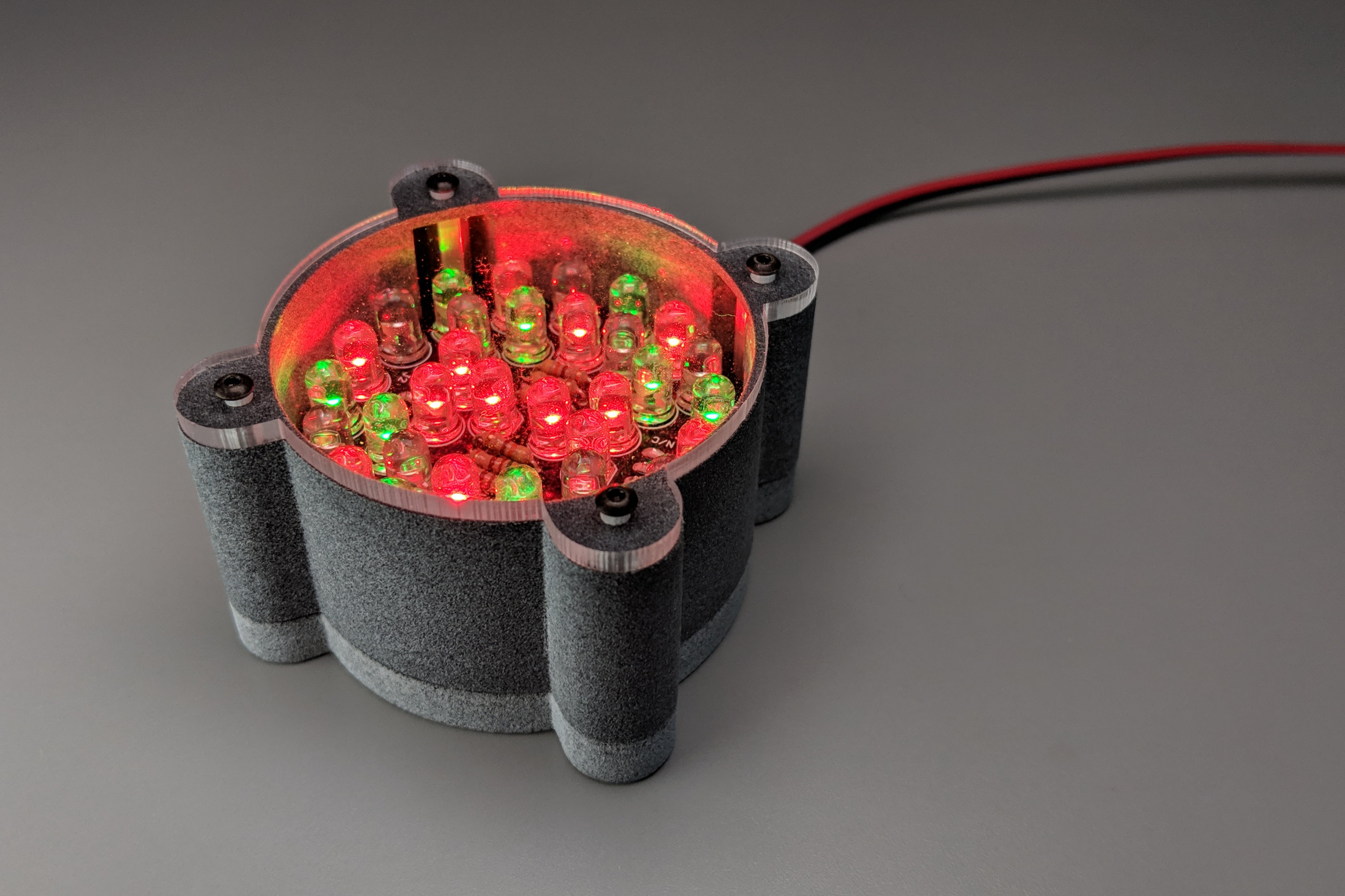
The finished light. It’s never too early to start thinking about the next version.
After disassembling the light several times to hold down the configuration button during power up, one change I would make to the hardware would be to make the button accessible without disassembling the light. The easiest way to accomplish this change would be to create a new board layout that uses a right-angle button, place the button close to the edge of the board, then finally place a small hole in the enclosure that permits pressing of the button with a small non-conductive object such as a toothpick.
Another upgrade would be to make the firmware upgradeable over the DMX interface. This would require a bi-directional RS-485 adapter for a PC or Mac and the installation of a bootloader in the PIC24’s FLASH memory. If the configuration button were held down during power up, the bootloader could listen for a command to load new firmware over the DMX interface. If the command was received, the upgrade would continue. If not, the bootloader would time out and jump into the existing firmware which could then permit configuring the operating mode and DMX address or jump to normal operation. This should only require software changes and thus be possible using the existing hardware.