After seeing this cube and this cube, I decided it was time to build an LED cube of my own leveraging the BeagleBone Black and FPGA work I had already done for my six-panel mini video wall. The cube project is essentially purely mechanical since the existing BBB software and FPGA code will work unmodified to drive the cube.
3D Printed Brackets
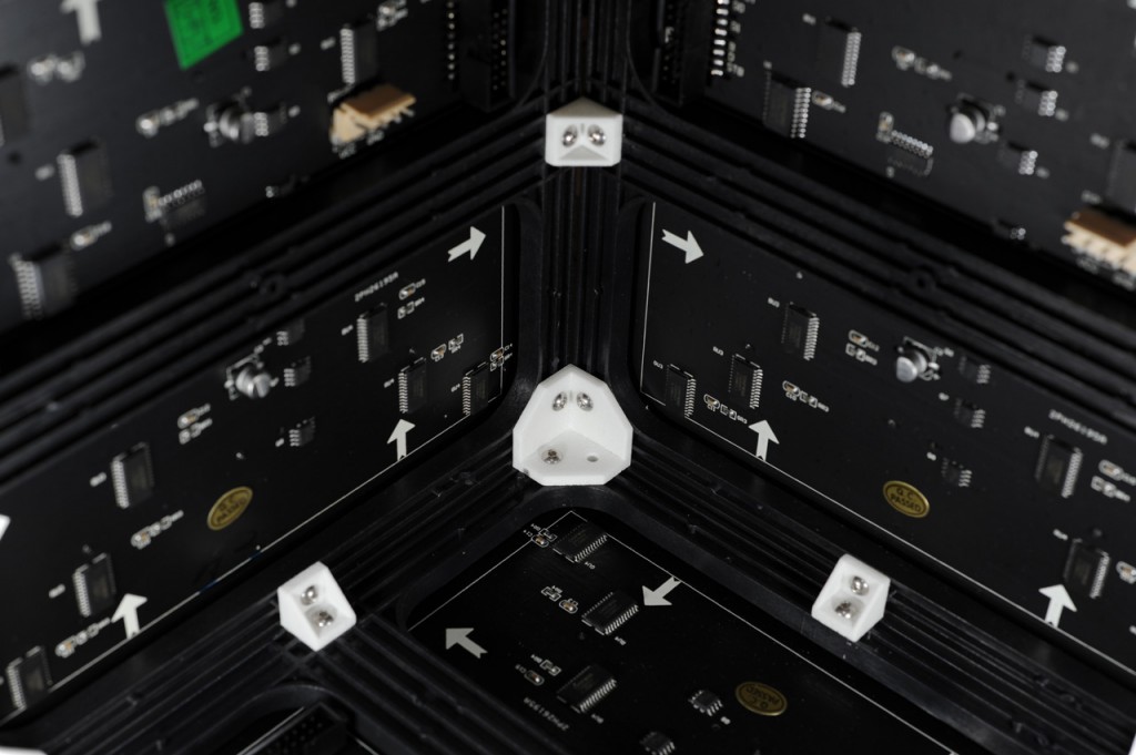
The first step in this project was to decide how to hold the six RGB LED panels together in a cube shape. I experimented with cutting and drilling aluminum angle iron into brackets to hold each panel to its neighbors. That experiment worked but was not easy to replicate. I finally decided to draw a set of brackets using Sketchup and have the brackets 3D printed. The brackets would attach at the corners and midpoints of each panel. Since I do not own a 3D printer, I used sculpteo.com to print the brackets out of white nylon.

3D printed brackets. The larger brackets hold the corners together. The small brackets hold the midpoints together.
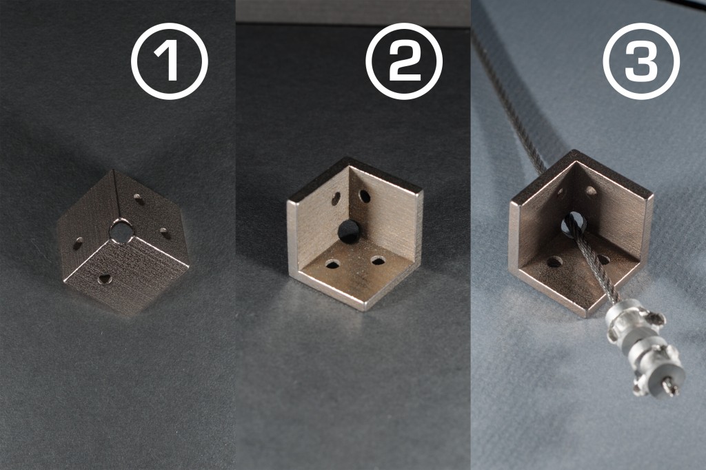
I wanted to be able to hang the cube from the ceiling. Rather than hang the cube by its power cord or networking cable, I decided to hang the bracket using a piece of wire rope. I swaged two stops on to one end of the wire rope. The wire rope and stops are a bit rough and would eventually wear through the plastic nylon corner so I used shapeways.com to 3D print a pre-drilled hanging bracket for the top corner out of stainless steel.
Both the Sketchup and STL files for each of these different brackets are in my github repository.
Panel Order
The next step was to decide the order of the panels. I wanted to minimize the seams between images so I decided panels 1, 2, and 3 should connect at their sides then panels 4, 5, and 6 should connect at their sides. I also wanted the panel with the minimum number of wired connections to be the lid. Panel 1 only has one power connection and one data connection so it had to be the lid. Finally panels 1, 2, and 3 would slide sideways into panels 4, 5, and 6. This would make the corner where panels 1, 4, and 5 come together the top.
Construction
The next step was to assemble the cube using the brackets and M3 x 6mm screws.
The lid panel is secured using friction. I cut the heads off four longer M3 screws and threaded those into the four corners of the lid panel. Friction and gravity are enough to hold the lid panel on top of the cube.
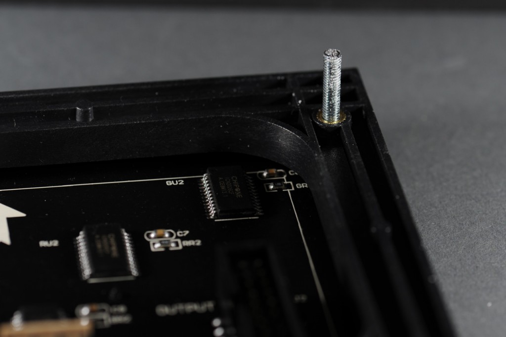
One of four corners of panel 1, the lid panel, showing the M3 post used to hold the lid on to the cube.
Temporarily assemble the cube and mark the corners of the panel where the wire rope will exit the cube.
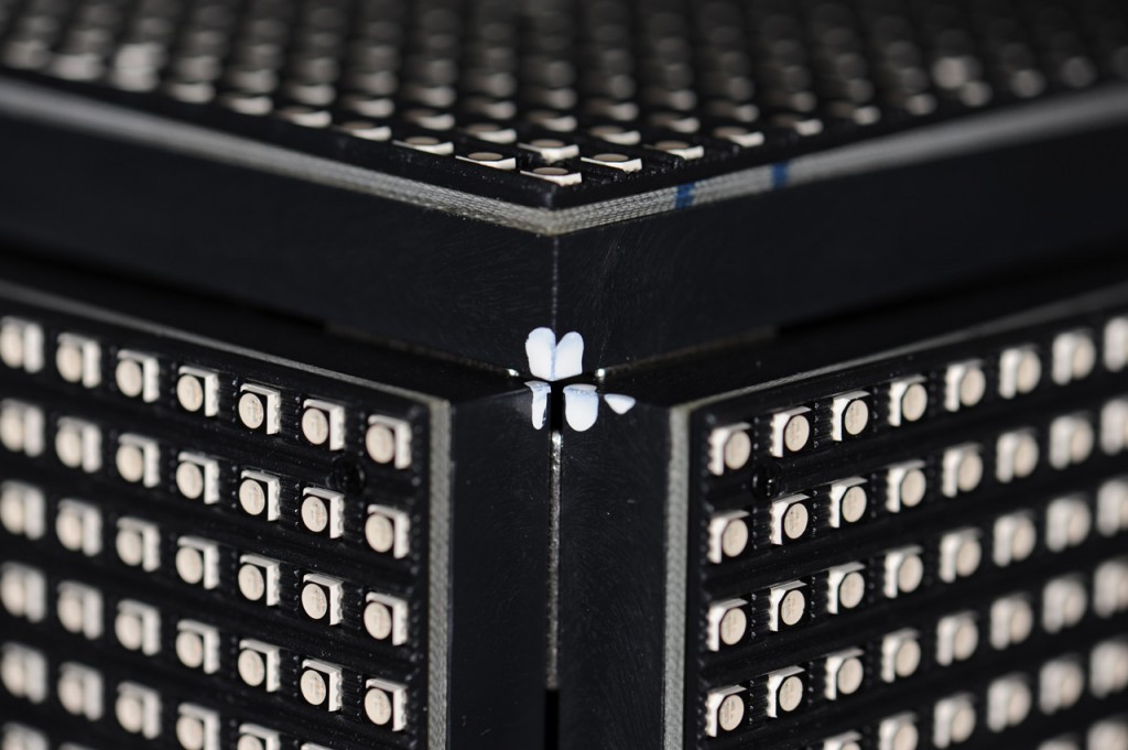
Disassemble the marked panels and use a rotary tool or file to knock the corners of the panels down just enough for the wire rope to exit the cube. Labeling the panels with tape makes it easier to keep track of which panel is which as the cube is being assembled.

The corners of panels 1, 4, and 5 were they meet at the top of the cube. The corners were knocked down just enough with a rotary tool for the wire rope to exit the cube.
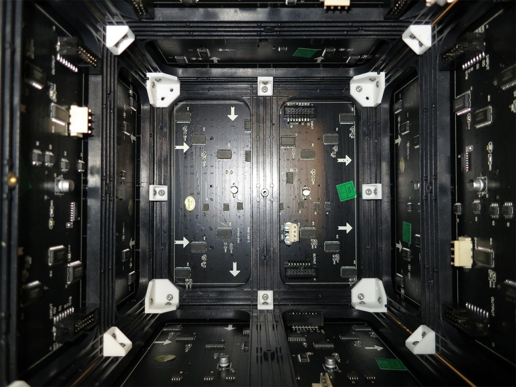
Complete the mechanical assembly of the cube using seven of the nylon corner brackets and eight of the nylon side brackets. The corner brackets will need to be rotated to accommodate the holes in the panels.
Electrical Connections
Now wire the cube. Connect the output of panel 6 to the input of panel 5, the output of panel 5 to the input of panel 4, etc., until finally connecting the output of panel 2 to in the input of panel 1. You’ll need to make a slightly longer ribbon cable assembly to connect the output of panel 4 to the input of panel 3. Connect the output of the LogiBone FPGA board to the input of panel 6.
After making the data connections, use three of the wire harnesses that came with the LED panels to supply power to the cube. I used a wire nut to join all the ground connections together and another wire nut to join all the +5V connections together. These were connected using some hookup wire to a 2.1mm DC barrel jack that mates with the plug on my +5V DC power supply.
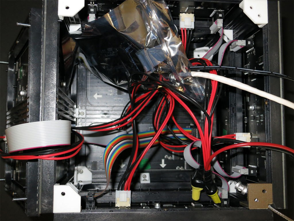
Wired cube interior. The BBB and LB FPGA boards are inside a plastic bag until a proper mounting bracket can be fabricated.
Be sure to use electrical tape to insulate any exposed power conductors and secure any cables that could come loose inside the enclosure. I have the BeagleBone Black and LogiBone FPGA board inside a plastic bag to keep them from shorting to any exposed conductors on the LED panels. This is a temporary measure (beware of heat!) until I have time to design a bracket to mount the BBB and LB boards to the inside surface of one of the LED panels.
The Finished Product
Here’s a photo of the finished cube hanging in my basement.
Using a Stand to Display the Cube
I also built a small stand out of dowel rods and MDF plywood. I’ve yet to paint the stand. If you would rather use a stand than hang the cube, the magic angle for cutting the dowel rods is 55 degrees. The stand still needs to be painted flat black.
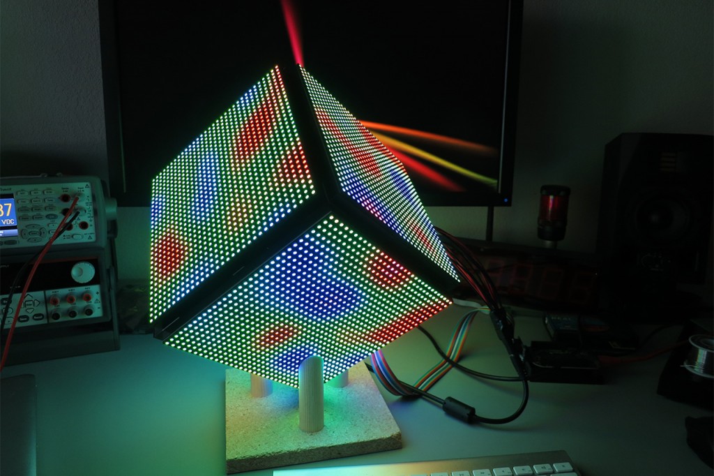
The cube sitting in its stand on my desk. The dowel rods are cut at 55 degrees and hold the cube with the top corner pointing straight up. The stand still needs to be painted black.
Some Ideas for Improvements
The interior of the cube gets quite warm. Ideally the BBB and LB would be located in a plastic housing attached to the wire rope above and outside the cube. A short ribbon cable would then run from the plastic housing to the interior of the cube. Lastly, I need to install the wireless drivers and connect to the BBB over WiFi instead of using a wired Ethernet cable. This would greatly reduce the bulky wiring exiting the top of the cube.


