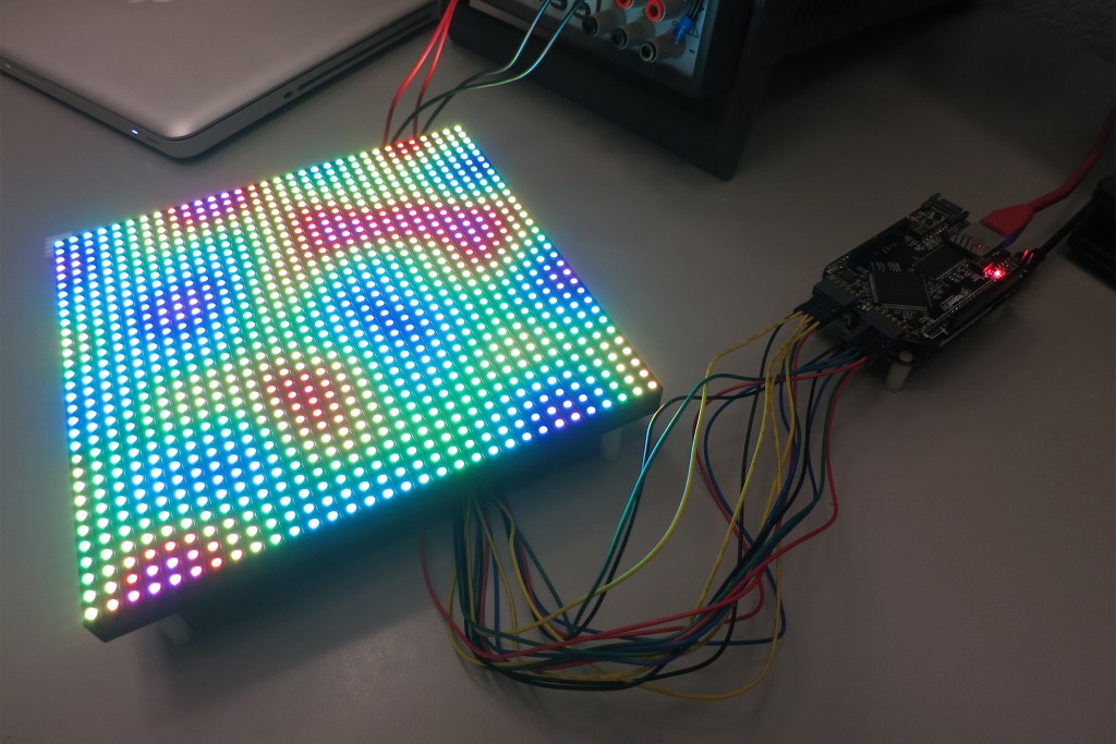
My latest project uses a BeagleBone Black and a Xilinx Spartan 6 LX9 FPGA to drive a 32×32 RGB LED matrix.

BeagleBone Black + LogiBone FPGA board driving a SparkFun 32x32 RGB LED panel.The displayed pattern is a frame from a Perlin noise pseudorandom sequence.
This project lets me display cool and interesting patterns on a matrix of 32×32 RGB LEDs. That’s 1024 RGB LEDs or 3072 individual LED chips that need to be controlled! Rather than attempt to control all the LEDs in software only or using one of the BBB’s programmable real-time units (PRU), I decided to use the CPU to generate the patterns and use the FPGA to handle the heavy duty task of refreshing the LEDs.
Using the FPGA to refresh the LEDs leaves me with nearly 100% of the BBB CPU available to generate patterns and lets me implement 12-bit color at a refresh rate of 200Hz. A 200Hz refresh rate has no perceptible flicker and prevents scan lines from showing when photographing or filming the panel. A typical 12-bit color software implementation using the PRU to refresh the panels only refreshes at 50 to 60Hz.
Having the CPU free to compute patterns rather than refresh the display lets me generate some rather complicated patterns that otherwise might not be possible. Right now the most complicated and interesting pattern is seamlessly looping Perlin noise but other various abstract patterns, animated GIFs, text, etc., can be displayed.
Seamlessly looping Perlin noise running at 50Hz on 1024 pixels requires 102,400 3D Perlin noise calculations per second. Using floating point math with no compiler optimization, this quickly burns through the BBB CPU cycles. Had I attempted to refresh the panel using a small embedded processor such as an Arduino, I wouldn’t have had the CPU bandwidth available to both calculate this complicated pattern and refresh the display.

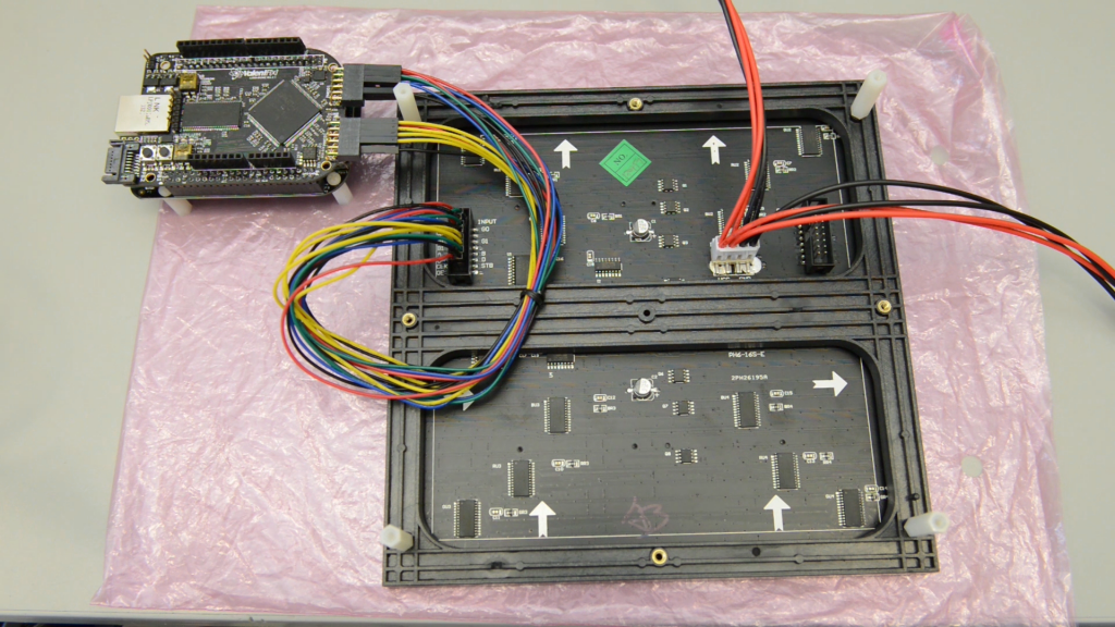
The wiring that is required to interface the BBB and LogiBone FPGA board to the 32x32 RGB LED panel.
To build this project, I used a stock BeagleBone Black SOC board, a ValentFX LogiBone FPGA board with a Xilinx Spartan 6 LX9 FPGA, a 32×32 RGB LED panel from SparkFun, and some jumper wires from Pololu Robotics. The LogiBone FPGA board was a beta unit acquired through their Kickstarter campaign. To build and simulate the FPGA, I used the free Xilinx WebPack tools. Being free, the Xilinx WebPack tools permit hobbyists (or anyone building small designs) to simulate, synthesize, map, and place and route code for a select set of Xilinx’s devices.
Speaking of simulation, do it! The very first bit file I loaded into the FPGA board worked the very first time I loaded it except that I had a mirror image on the display from feeding the RGB data into the display right-to-left instead of left-to-right. I reversed the order, ran another sim, and built another part. Bingo. Second try. Perfection.
After building everything and getting everything to work, I made a short video demonstration of the project, wrote a complete tutorial on how anyone with a BeagleBone Black, a LogiBone FPGA board, and an LED panel can replicate results, then uploaded all the required code and files to github. Below are links to the code, tutorial, and video.
Links to Project Files:
Enjoy!
