

The Nixie tube connected to the socket / driver board and the socket / driver board connected to the upside down power / controller board.
The first in this series of posts described building a socket and driver board for a Dalibor Farny R|Z568M Nixie tube and driving the tube using a power supply and Particle Photon from another Nixie project. This post covers building a power supply and controller board that mounts underneath the socket and driver board to power the Nixie tube and control the displayed digits.
Schematic
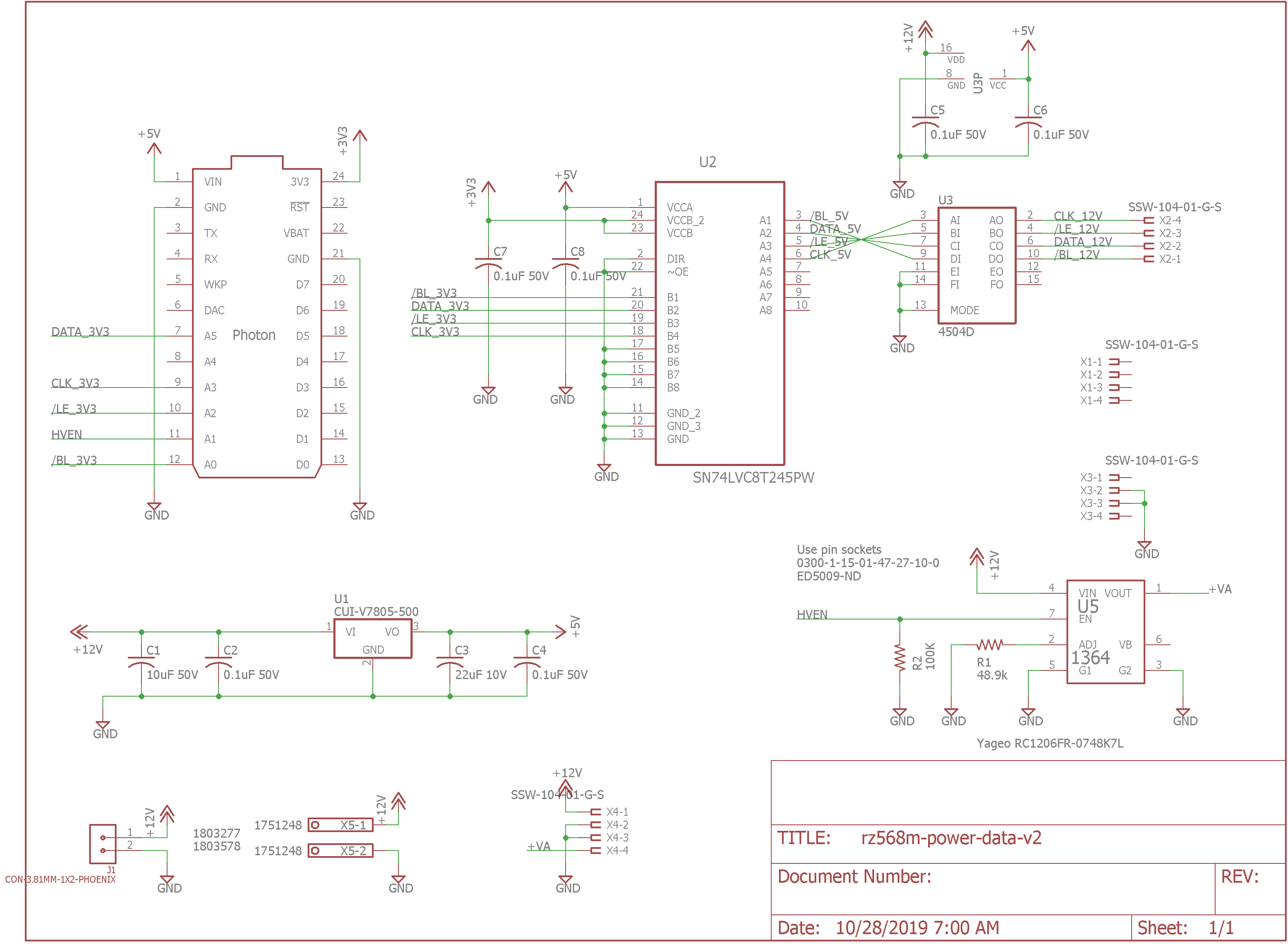
Schematic.
The schematic for this project is almost identical to the schematics I’ve used in the past for driving IN-4, IN-12, and IN-18 Nixie tubes with a Microchip HV5522. The major functional blocks are power supplies, a Particle Photon, and some voltage level translators. The only real differences between this design and past designs are the number of header sockets and the type of power connector.
Power Supplies
This project requires three supply voltages. The Particle Photon requires 5 volts, the HV5522 serial-to-parallel converter requires 12 volts, and the Nixie tube’s anode requires 170 volts. The Particle Photon also has its own on-board 5 volt to 3.3 volt regulator.
I chose to power the board from an external 12 volt supply. This provides the 12 volts required by the HV5522. 12 volts is also easy to step down to 5 volts and up to 170 volts. The 12 volt power input is on J1 or X5. The footprints for these two components are on top of each other on the board. You can stuff either the pluggable terminal block or the fixed screw terminal block when assembling the board.
U1 and C1 through C4 form the 5 volt power supply. U1 is a CUI V7805-500 switching linear regulator replacement. It has a wide 7.5 V to 32 V input voltage range and can supply 500 mA of current with an efficiency of up to 93%. Low-ESR ceramic capacitors C1 and C3 are chosen according to the data sheet for the device and are required for stability. C2 and C4 provide additional filtering.
The 170 volt power supply is a Taylor Electronics Services 1364LN 1364 HVPS horizontal low-noise power supply. R1 sets the output voltage to 170 volts and R2 keeps the power supply disabled until the Particle Photon software is running and is ready to enable the high-voltage supply. From the formula in the data sheet, R1 should be 48.871 k for an output voltage of 170 volts. The chosen 48.7 k resistor sets the output voltage to 170.04 volts.
Particle Photon
Controlling everything is a Particle Photon. The Particle Photon has a very comprehensive set of libraries for Wi-Fi, SPI, and time of day clocks. The firmware can also be flashed over the air which allows the Photon to be embedded into the project then never touched again. We’ll use all these functions. It requires about 300 mA at 5 volts and includes an on-board 3.3 volt regulator for its circuitry.
Voltage Level Translation
The SPI serial interface on the Photon uses 3.3 volt I/O. The HV5522 requires 12 volt logic level inputs. I could not find any parts that directly convert 3.3 volt logic to 12 volt logic. Instead, I’m using a Texas Instruments SN74LVC8T245PW to convert from 3.3 volt logic to 5 volt logic then a CD4504D to convert from 5 volt logic to 12 volt logic. Fortunately, the I/O only runs in a single direction from the Photon to the HV5522 so we do not need to convert any 12 volt logic back down to 3.3 volt logic.
Board
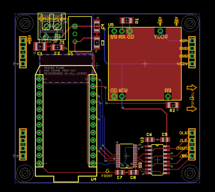
Board.
The board is designed to mount upside down and underneath the socket and driver board. The M3 screw holes in the corner and the 0.1″ pitch header sockets on the rear of the board align with the screw holes and header pins on the socket / driver board. The rest of the components are mounted on the front of the board. The two power connector component footprints overlap intentionally so that either a pluggable terminal block or screw terminal block may be used with the board.
Assembly
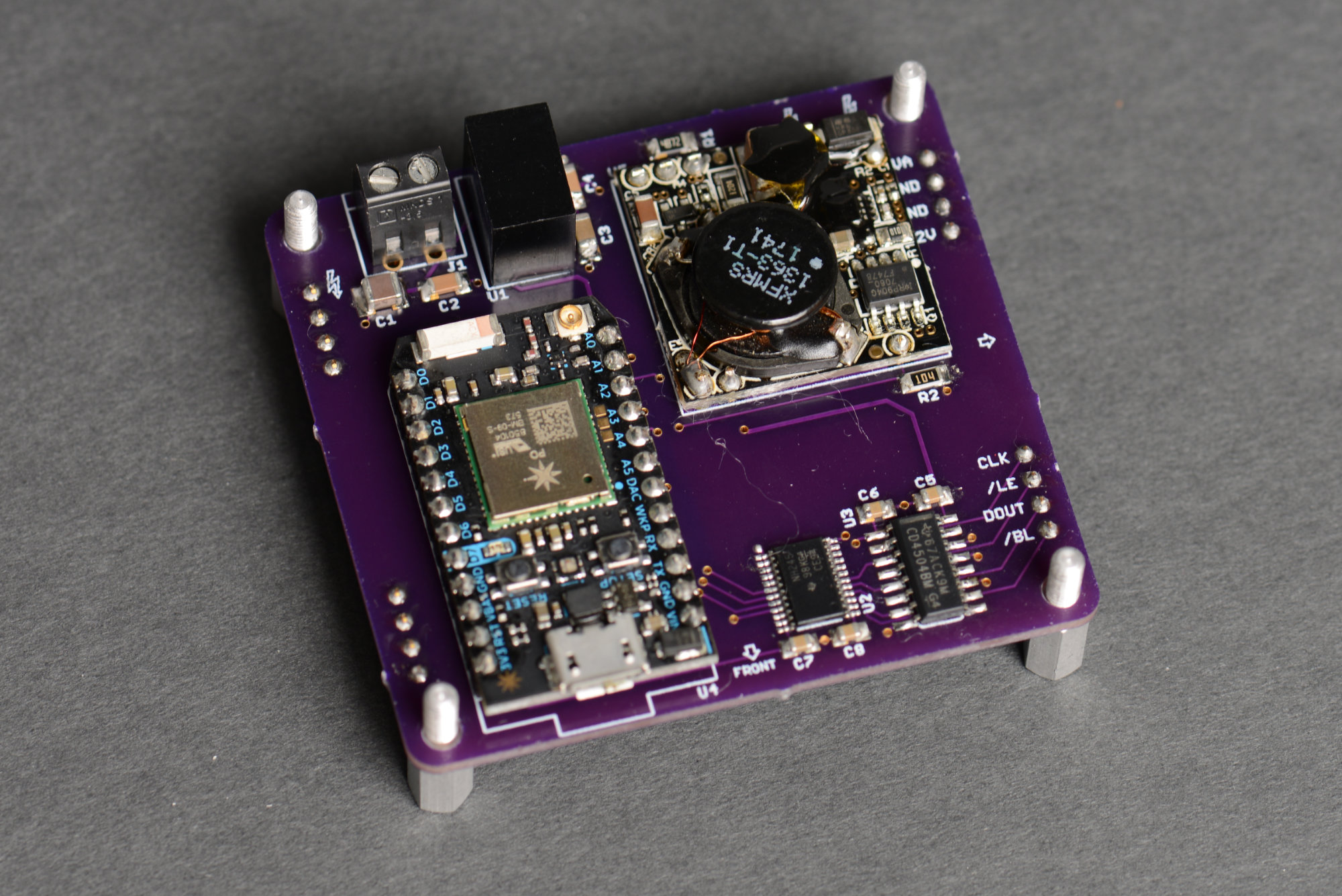
The assembled power / controller board for this Nixie tube project.
Assembly is fairly straight forward. I soldered the header sockets on the board first. I used the same technique to mechanically align and secure the header sockets for soldering that I used on the socket / driver board. After the header sockets were soldered, I soldered the surface mount components then the Photon, high-voltage power supply, 5 volt regulator, and power supply screw terminal block.
I could have used header sockets for the Photon and power supply instead of soldering them directly to the board but this would have made the board sandwich and the resulting enclosure taller which I did not want to do.
Bringup

Close up of the tube and two boards mounted together. The top standoffs are threaded F/F M3 11 mm standoffs. The bottom standoffs are threaded F/M M3 10 mm standoffs.
To bring up the board, I connected it to a bench supply using the screw terminal block on the board. I set the bench supply to 12 volts with a current limit of 300 mA. I adopted the Photon into my account using Particle’s phone app then downloaded the software from the previous post on the socket / driver board to it. Once the software was running, I used a DMM to measure the anode voltage at the header sockets. It measured slightly under 170 volts.
I turned off the bench power supply output and connected the two boards together as shown in the photograph above. When I powered the boards back up, the Nixie tube began counting from 0 to 9 just like when I used the power / controller board from my IN-18 clock design. The boards and Nixie tube nominally consume 160 mA at 12 volts which is 1.92 Watts.
Conclusion
Now that we have a two board sandwich that successfully powers and controls the Nixie tube, it’s time to design an enclosure for everything. Designing the enclosure is the subject of the next blog post.