
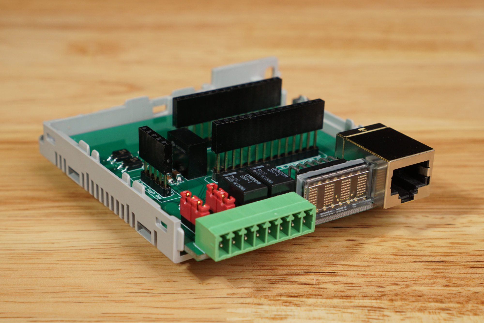
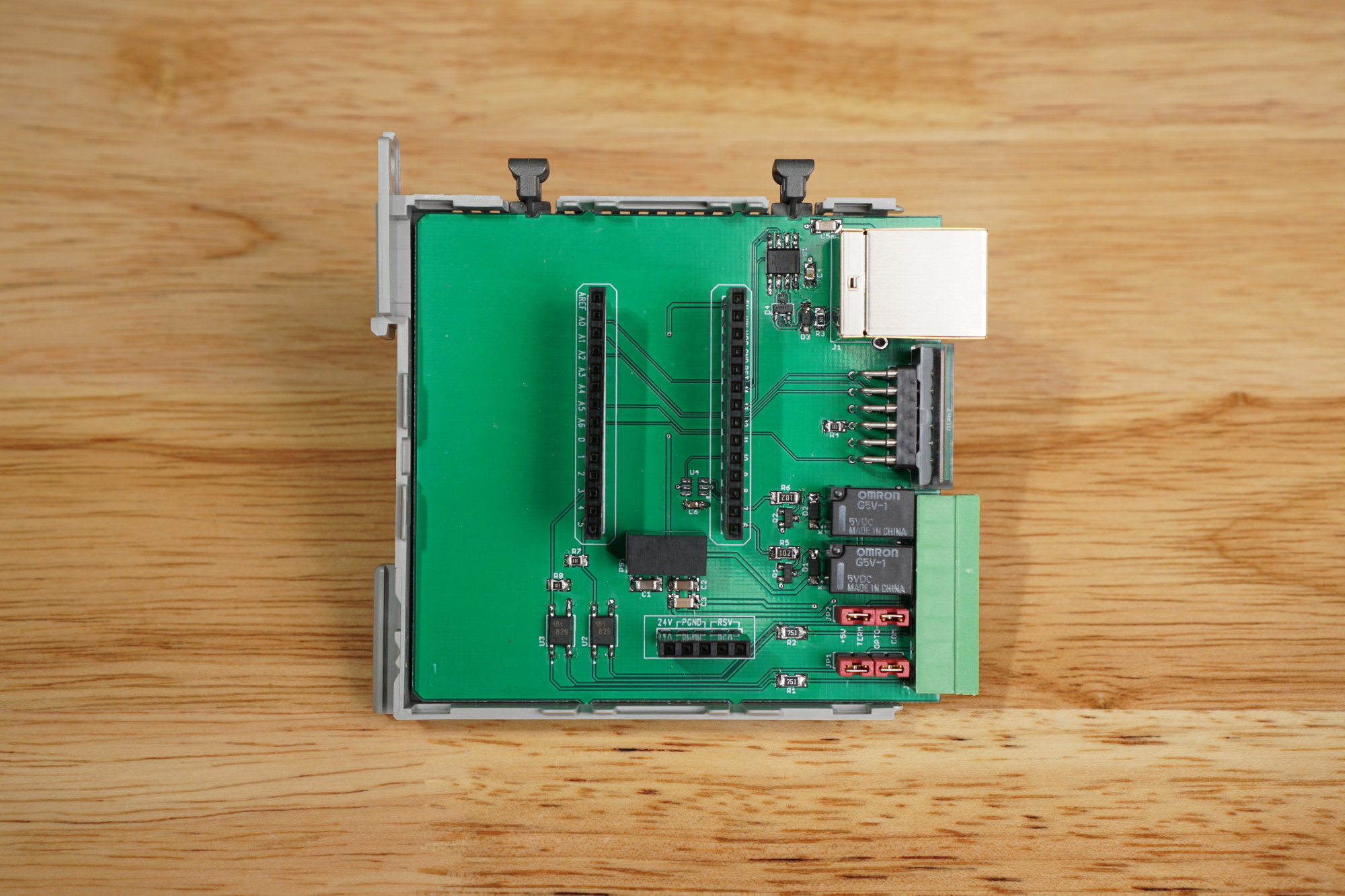
Inside my first add-on module for the P1AM-100 open source PLC. Two optically-isolated inputs, two relay outputs, a display, a half-duplex RS-485 transceiver, and a serial EEROM with a MAC address for the Ethernet module. The enclosure and headers are included in the P1AM-PROTO prototyping module. Not shown is the lid of the enclosure.
In January 2020, Automation Direct launched their ProductivityOpen family of open-source programmable logic controllers (PLC’s). The first controller in the series, the P1AM-100, is based on the Microchip ATSAMD21 microcontroller and programmed using the Arduino development environment. To encourage development, they launched a prototyping module alongside the controller. The prototyping module consists of a piece of perfboard, the required connectors, and a housing.
I was already familiar with Automation Direct and their PLC and pneumatic products after building my crate beast and zombie containment unit Halloween props a few years ago. I was intrigued by this new controller from a familiar company, the CPU selection, and the possibility of building my own modules that could tie in to the controller for future projects. I set out to build a couple of add-on modules but first needed to take a closer look at the controller and its available add-ons.
The ProductivityOpen PLC System
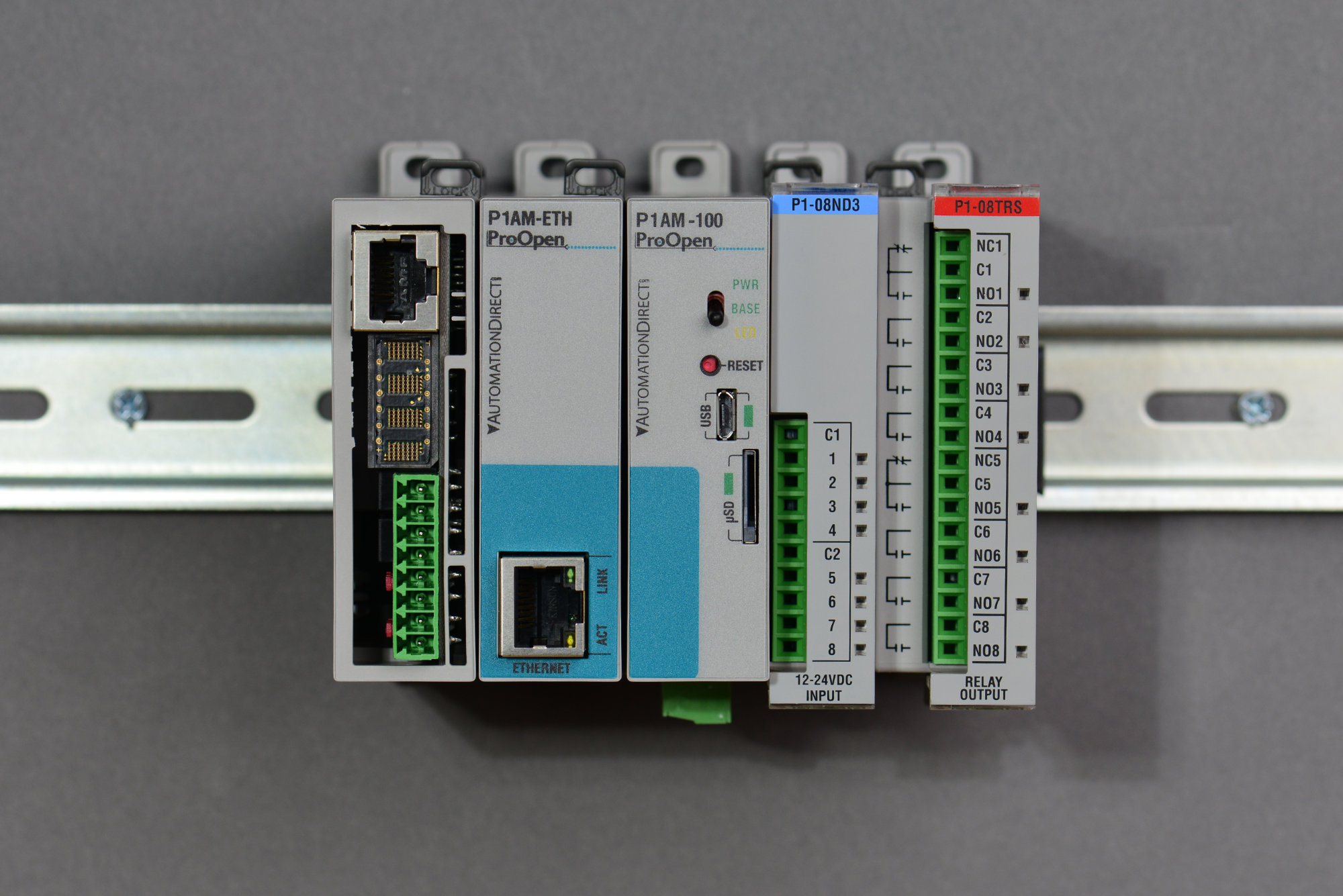
The ProductivityOpen and Productivity 1000 family. Left to right: P1AM-PROTO prototyping module with my design inside it, P1AM-ETH Ethernet module, P1AM-100 controller, P1-08ND3 input module, P1-08TRS output module.
The core of the ProductivityOpen PLC system is the P1AM-100 PLC. It’s the middle box in the photo above. The P1AM-100 is a ruggedized industrial controller with full UL and CE regulatory approval. It’s based on a the Microchip ATSAMD21 microcontroller and programmed using either the Arduno IDE or Automation Direct’s Productivity Blocks instead of the normal proprietary Productivity software suite. The ATSAMD21 is the same microcontroller that’s used on the Arduino MKR1000 board as well as the ever-popular Adafruit Feather M0 series of boards.
The PLC includes USB connectivity for programming, a micro SD card slot, a real-time clock, a switch, a user LED, and a few status LEDs. The PLC also has a watchdog circuit external to the ATSAMD21 that’s designed to reset the ATSAMD21 should it stop running. The PLC can be powered using a power supply that connects to the left of the P1AM-100 (not pictured), a USB cable, or a 24 volt supply connected to the 3 pin connector on the bottom of the PLC.
Proprietary Modules on the Right
On the right hand side of the PLC is a connector to permit using all the Productivity 1000 series modules with the PLC. The P1AM libraries include function to use these modules inside your Arduino code but the operation of the interface and the modules themselves are not open source. Pictured above are a P1-08ND3 input module and a P1-08TRS relay output module. All the P1000 modules require 24 volts and will not run if only a USB supply is used.
Open Source Modules on the Left
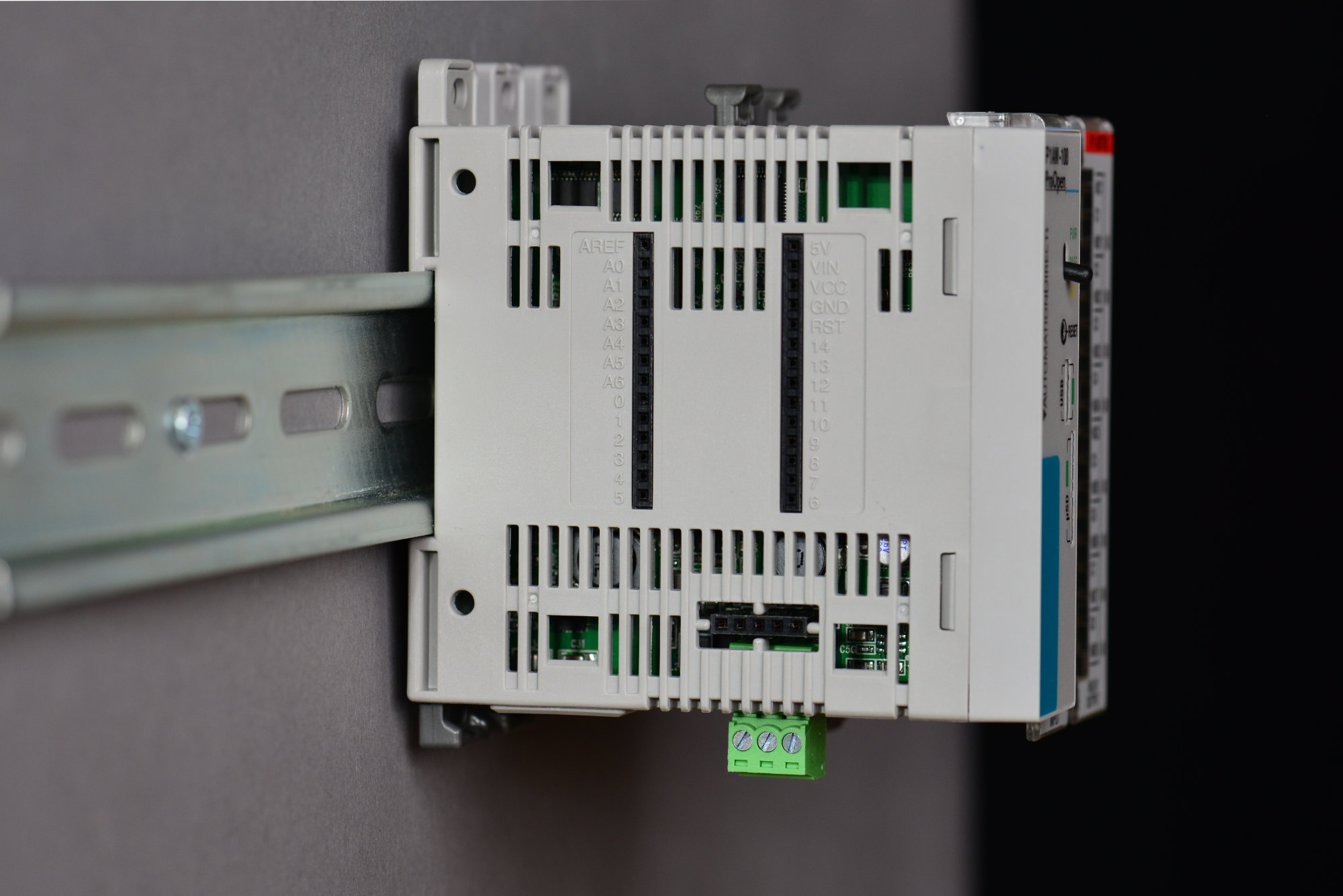
Arduino MKR1000 compatible header sockets on the left side of the P1AM-100 PLC.
The left side of the controller is where things start to get interesting. The left side of the PLC has Arduino MKR1000 compatible header sockets. Any existing MKR1000 shields can plug directly into these sockets and work with the controller. In addition, Automation Direct offers three modules of their own.
The P1AM-ETH offers Ethernet connectivity for the system and is similar to the Arduino MKR ETH shield but comes with UL and CE approvals and a plastic enclosure. It’s immediately left of the controller in the photo at the top of this section. The P1AM-GPIO is a simple breakout board that brings the I/O on the MKR header sockets out to screw terminals.

The contents of the P1AM-PROTO prototyping kit.
The P1AM-PROTO though is the most interesting of these modules. It’s a blank slate consisting of a plastic enclosure, a piece of perf board, a set of header sockets, and a blank front panel. The contents of the P1AM-PROTO kit is shown in the picture above. If you have a simple circuit, you can solder and wire wrap the circuit directly on the provided piece of perf board. If you have a more complex design, you can replace the perf board with a circuit board of your own design.
What’s Open Source and What’s Not Open Source
The ProductivityOpen series is an interesting blend of open source and proprietary designs. The Ethernet, GPIO, and prototype modules are 100% open source. Full schematics and Gerbers are provided. The Productivity 1000 modules remain proprietary but a software library is provided to use them in your open source designs.
The core of the product line, P1AM-100 PLC, is a mix of proprietary and open source parts. Schematics are provided for the ATSAMD21 and most of the “logic” type hardware surrounding it. Full schematics and Gerbers are not available.
This is sufficient information to design hardware to plug into the MKR1000-compatible header sockets and write software to control your hardware. The interface to the P1000 modules and the ruggedized 24 volt power supply circuit remain proprietary. The Arduino-compatible bootloader is open source. There’s a footprint for a ARM SWD programmer/debugger on the board but it is not populated.
Getting Started
The documentation for the project contains the getting started guide for the PLC and guides to using the CPUs, shields, and P1000 modules. It includes instructions for downloading the Arduino IDE and installing the required board files and libraries. It also includes some brief snippets of example code showing how to use the shields and P1000 modules.
Automation Direct has a GitHub repository containing more detailed examples for many functions of the PLC and modules. FACTS Engineering has a GitHub repositories with the P1AM libraries and board files for the Arduino IDE and the design files for their open-source shields. The design files repository also contains a schematic of the core functionality of the P1AM-100.
Finally, Automation Direct has a section of their forums dedicated to the P1AM-100 and its shields and modules.
Building an Add-On Module
After playing around with the CPU and Ethernet shield for a while, I definitely wanted to build my own add-on shield to fit inside the P1AM-PROTO prototyping enclosure. For my first module, I eventually decided on the following feature set:
- Some optically isolated inputs.
- Some relay outputs.
- Some sort of a display or other indicators.
- An RS-485 interface so I could run the DMX controller software I wrote for my DMX FeatherWing project on the ruggedized P1AM instead of the Feather M0.
- A Microchip EUI-48 serial EEPROM so I could assign a unique Ethernet MAC address to the WIZnet Ethernet controller inside the P1AM-ETH module.
This would be enough features for a modest Halloween prop controller, a new controller for my garage door overhead lights, or running my DMX controller software from my DMX FeatherWing project on the P1AM instead.
Regardless of the feature set, I needed a library for my PCB design software that at least had an outline of the board with the PTH pads for the header sockets in the correct location.
Creating an Eagle PCB Library for the P1AM Prototyping Module
I started my add-on module design by building a library containing a PCB footprint with the board outline, silkscreen layers, and pads for the header sockets, and a schematic symbol for the Arduino MKR headers.
Automation Direct doesn’t provide native PCB design files for the P1AM-PROTO perfboard but they do provide the Gerbers used to manufacture the perf board. Luckily, my PCB design software, Eagle PCB, has an option to import Gerbers into a board design.
If you download and unzip the perf board Gerbers, you’ll see eight files in the archive:
- P97868.GBL — bottom traces
- P97868.GBO — bottom silkscreen
- P97868.GBS — bottom solder mask
- P97868.GKO — board outline
- P97868.GTL — top traces
- P97868.GTO — top silkscreen
- P97868.GTS — top solder mask
- P97868.XLN — drill file
We’re interested in the board outline, silkscreen, and drill files. Eagle cannot import a Gerber into a library package but you can import a Gerber into a board design then paste the board design into a library package. I imported the outline and silkscreen layers into a new board design. Here’s the resulting board layout:
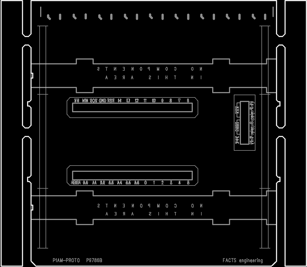
Board outline and silkscreen layers imported from P1AM-PROTO perf board Gerber files.
This board layout has everything we need to create a library for the part except the location of the drills for the header sockets. Since Eagle cannot import drills from an Excellon file, I also added the top trace layer to the design:

Added the top trace layer to the other imports.
This gave me the location of the drills even though I didn’t need the traces. At this point, I copy and pasted everything into a new library package. I removed the carriers on either side of the board then cleaned up the board outline so that it formed a continuous outer perimeter. I placed 1.0 mm PTH pads where the header sockets go using the top signal layer as a guide. Once the holes were placed, I deleted the top signal layer entirely, rotated the board ninety degrees clockwise, and changed the colors of the layers to make things more legible. Here’s the resulting library package:
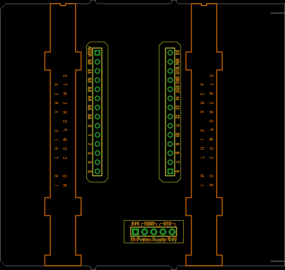
Eagle PCB library package created from P1AM-PROTO perf board Gerbers.
Note that all components need to stay outside the yellow outlines around the headers to avoid interference with the enclosure. Also components and through hole leads need to stay outside the orange outlines on the bottom of the board to avoid interference with the sliding latches on the enclosure.
The next step was to create a library symbol for the Arduino MKR headers and the five pin power header. Pretty simple:
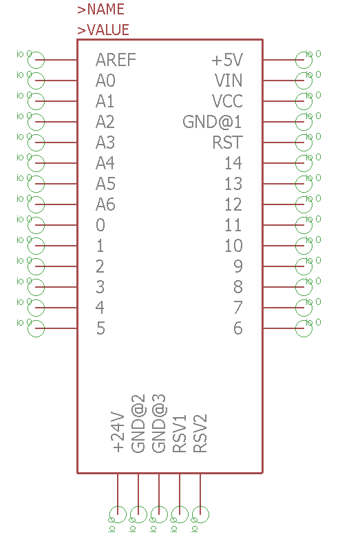
Schematic symbol for the MKR 1000 + P1AM headers.
Finally, I created a device containing the package and symbol and the library was done. My P1AM perf board library can be downloaded from my GitHub repository for this project. It has been used to fabricate four different boards now and they have all fit inside the P1AM-PROTO enclosure successfully.
The P1AM-100 documentation states that users should avoid using pins A3 and A4 if they plan on using the P1000 bus input/output modules. The user should avoid digital output 5 in their own designs as well if they plan to use the P1AM-ETH module alongside their design. The P1AM-ETH also uses the SPI bus pins so these need to be shared between your design and the module.
Add-On Module Schematic
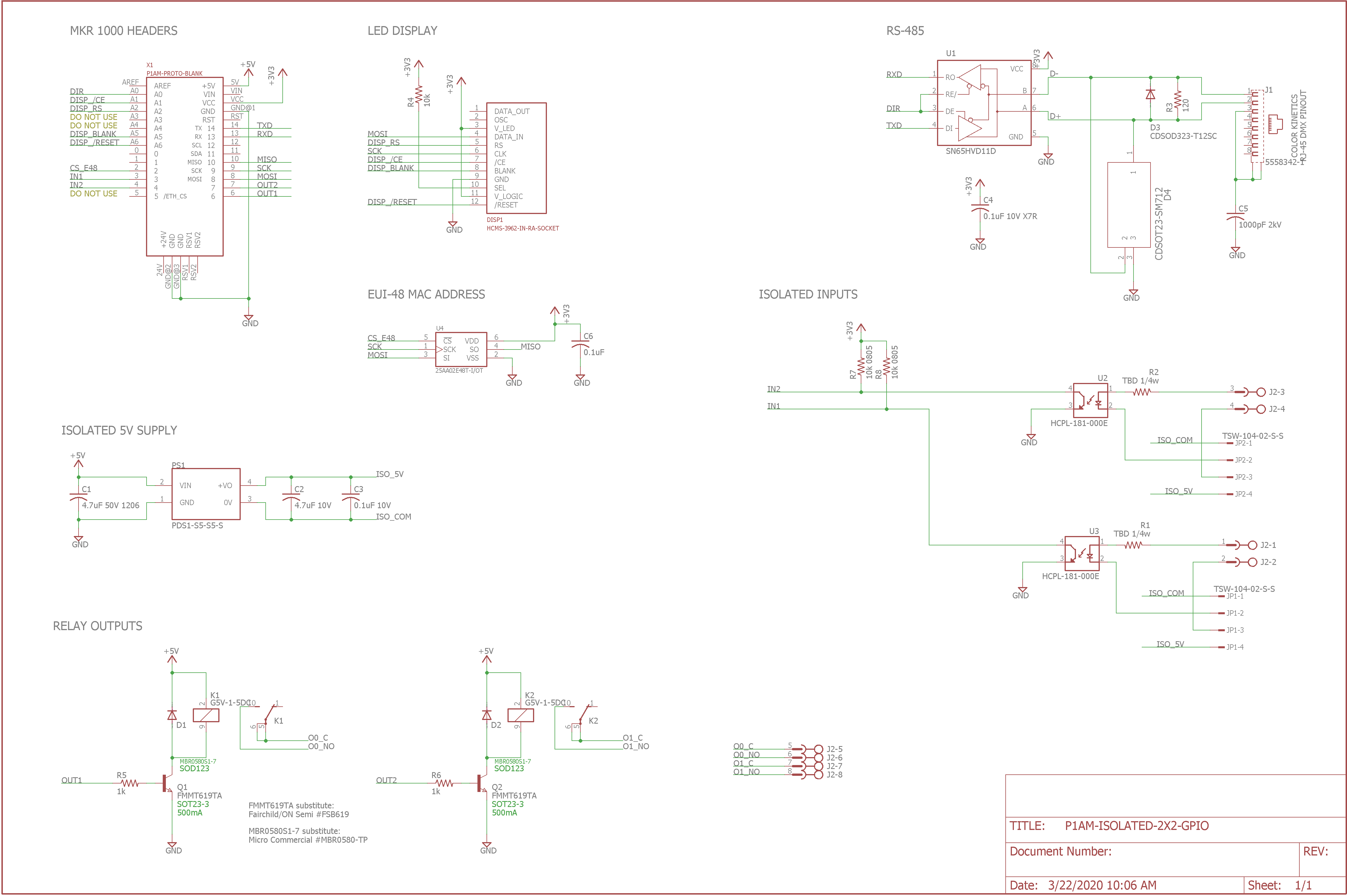
Schematic for my add-on module.
The next step was to create a schematic for my add-on module. After iterating through various input / output options, connectors, and displays to see what would fit on the board, I settled on the following feature set:
- Two optically-isolated inputs on a 3.5 mm pitch pluggable screw terminal strip.
- Two relay outputs. SPST / 1-Form-A / normally open on a 3.5 mm pitch pluggable screw terminal strip.
- Half-duplex RS-485 on an RJ-45 connector.
- A four character, 5×7 dot-matrix LED display.
- A Microchip EUI-48 serial EEPROM with a pre-programmed Etherrnet MAC address to use with the P1AM-ETH module.
Let’s look closer at each of these features and how they were implemented.
Optically Isolated Inputs

Optically-isolated input section of the schematic.
The diagram above shows the optically-isolated input circuitry. My inputs 1 and 2 are connected to digital input pins 3 and 4 respectively on the MKR headers. When no current is flowing through the optoisolator’s LED, its transistor is off and the 10k resistors pull the input to the ATSAMD21 high. When sufficient current is flowing through the optoisolator’s LED, its transistor is on and pulls the input line on the ATSAMD21 to ground.
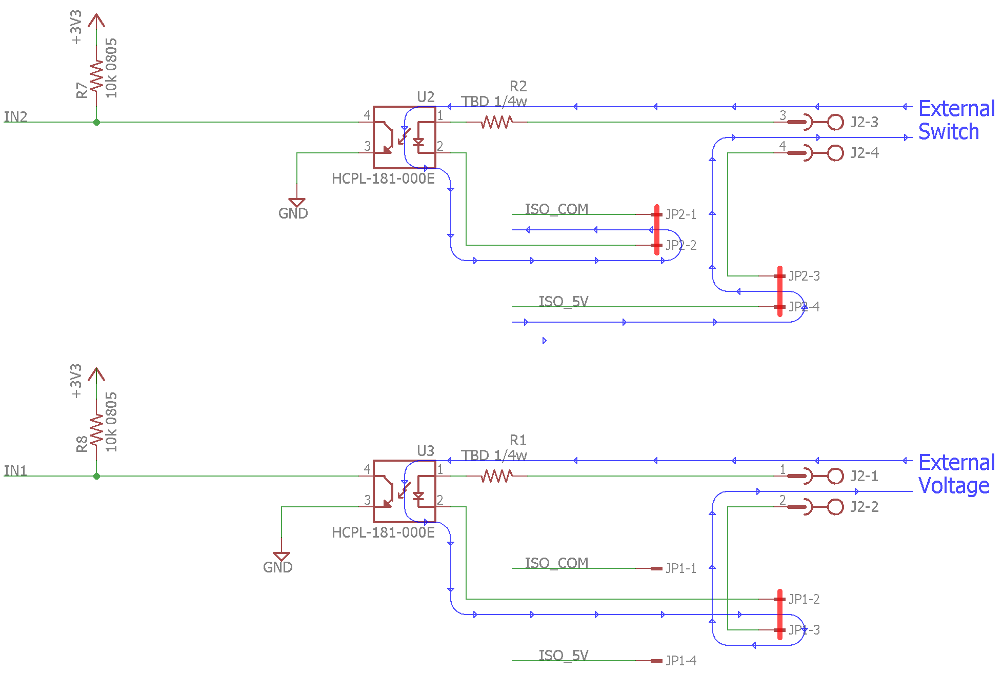
The top circuit shows the jumpers configured to use an external switch connected to the inputs. The bottom circuit shows the jumpers configured to use an external voltage connected to the inputs.
The optoisolator’s LED may be turned on by using either an external switch or an external voltage depending on the configuration of the jumpers in the circuit.
In the top circuit in the diagram above, two jumpers are used to connect pins 1 and 2 together and pins 3 and 4 together. In this configuration, 5 volts from the isolated supply is routed to the user’s external switch. When the switch is closed, current will flow through the optoisolator’s LED to the isolated supply’s ground and the LED will illuminate the photo transistor inside the optoisolator. This causes the ATSAMD21’s input to go low. When the switch is opened, current will cease to flow, the LED turns off, the transistor turns off, and the pull-up resistors will pull the ATSAMD21’s input high.
In the bottom circuit in the diagram above, a single jumper is used to connect pins 2 and 3 together. In this configuration, an external voltage can be connected to the screw terminals and used to turn on and off the LED inside the optoisolator. When a voltage is present, the LED turns on, the transistor turns on, and the ATSAMD21’s input is pulled low. When a voltage is not present, the LED turns off, the transistor turns off, and the ATSAMD21’s input goes high. The values of R1 and R2 need to be adjusted depending on the input voltage in this configuration.
Relay Outputs
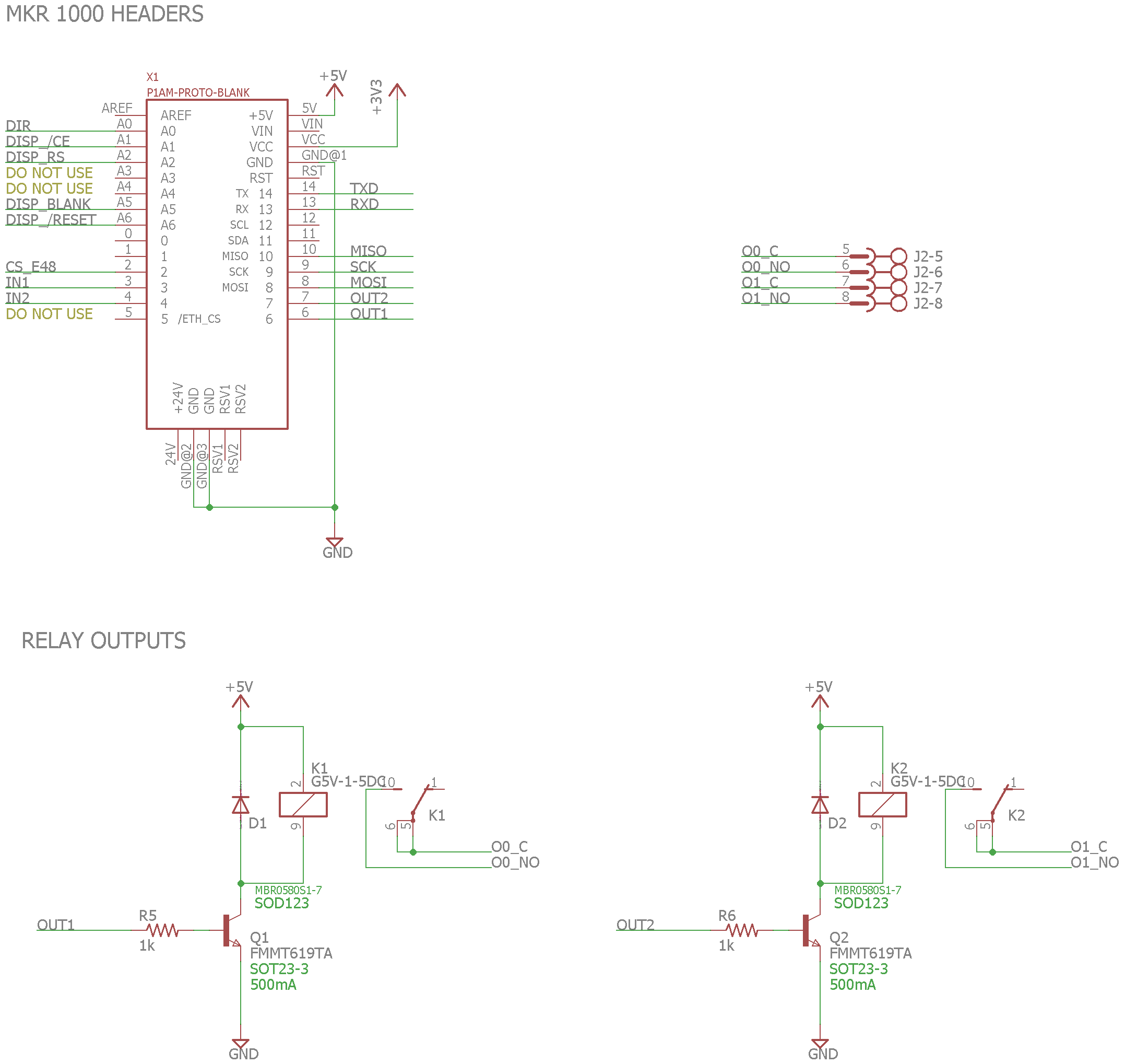
Relay output circuitry.
The schematic above shows the relay output circuitry. My outputs 1 and 2 are connected to digital outputs 6 and 7 respectively on the MKR headers. When one of the digital outputs is placed high by the ATSAMD21, a current flows into the base of the transistor. This turns on the transistor and allows current to flow through the relay’s coil. This in turn closes the relay’s contacts. When the digital output pin is placed low, the transistor turns off, the current through the coil ceases to flow, and the relay’s contacts open. The diodes protect the transistors against brief high-voltage transients when the relay is turned off.
RS-485
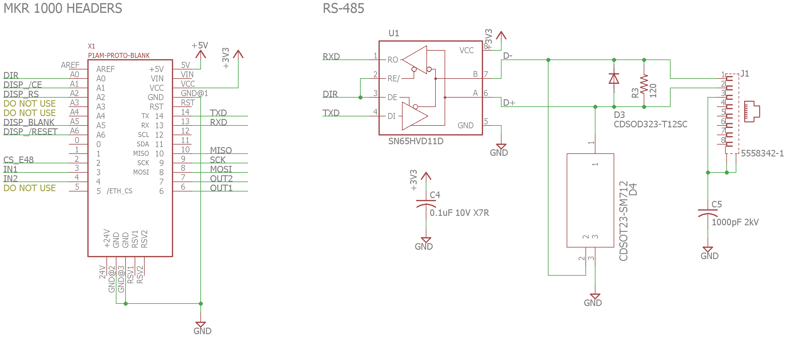
RS-485 circuitry.
The RS-485 circuitry is shown in the schematic above. Pin A0 should be configured as a digital output and is used to control whether the half-duplex RS-485 transceiver is in transmit or receive mode. The transmit and receive pins are connected to the transmit and receive pins on the MKR header. Serial data can be sent and received through an Arduino application using Serial1 and SERCOM5.
The two diodes provide additional ESD protection beyond the ESD protection built into the differential receiver. Their function is described in the TI application note Protecting RS-485 Interfaces Against Lethal Electrical Transients.
Display

The display circuitry.
I decided I needed a display on my project so I went with the coolest display I could find. The display is a Broadcom HCMS-3962 four-character, 5×7 dot matrix display mounted in a Mill-Max 299-43-312-11-001000 right angle socket. These displays have been around forever. They were originally made at HP for their instrumentaion products and somehow have survived the HP -> Agilent -> Avago -> Broadcom acquisition chain.
These displays aren’t practical for real applications because the quantity 1 price is US$36, but they’re still cool for a one off project like this one. The display is connected to the SPI bus and some digital output pins to select the display, the display’s registers, and control blanking and reset.
Serial EEPROM / Ethernet MAC Address
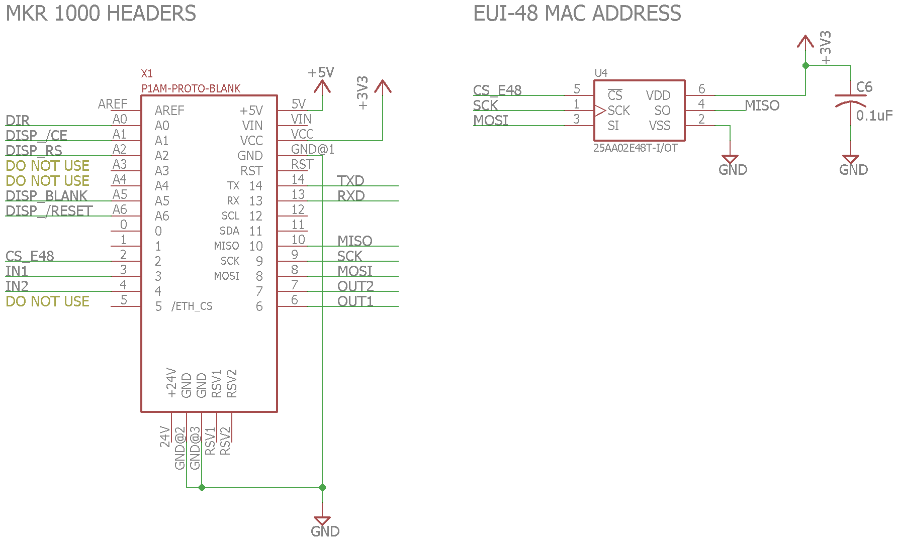
Serial EEPROM with unique Ethernet MAC address circuitry.
The final feature is a serial EEPROM with a pre-programmed Ethernet MAC address. In the case where I use this module and the P1AM-ETH together, I can read the MAC address from the serial EEPROM and pass it to the Arduino Ethernet library when initializing the Ethernet hardware.
Purchasing a block of MAC addresses for small projects like this is not feasible. Instead I’m using a Microchip EUI-48 serial EEPROM that contains a pre-provisioned, globally-unique, and write-protected MAC address. The alternative for devices that will not be used outside your local network is to use a locally administered address from one of the locally administered address pools.
Board Design
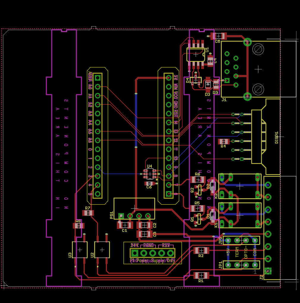
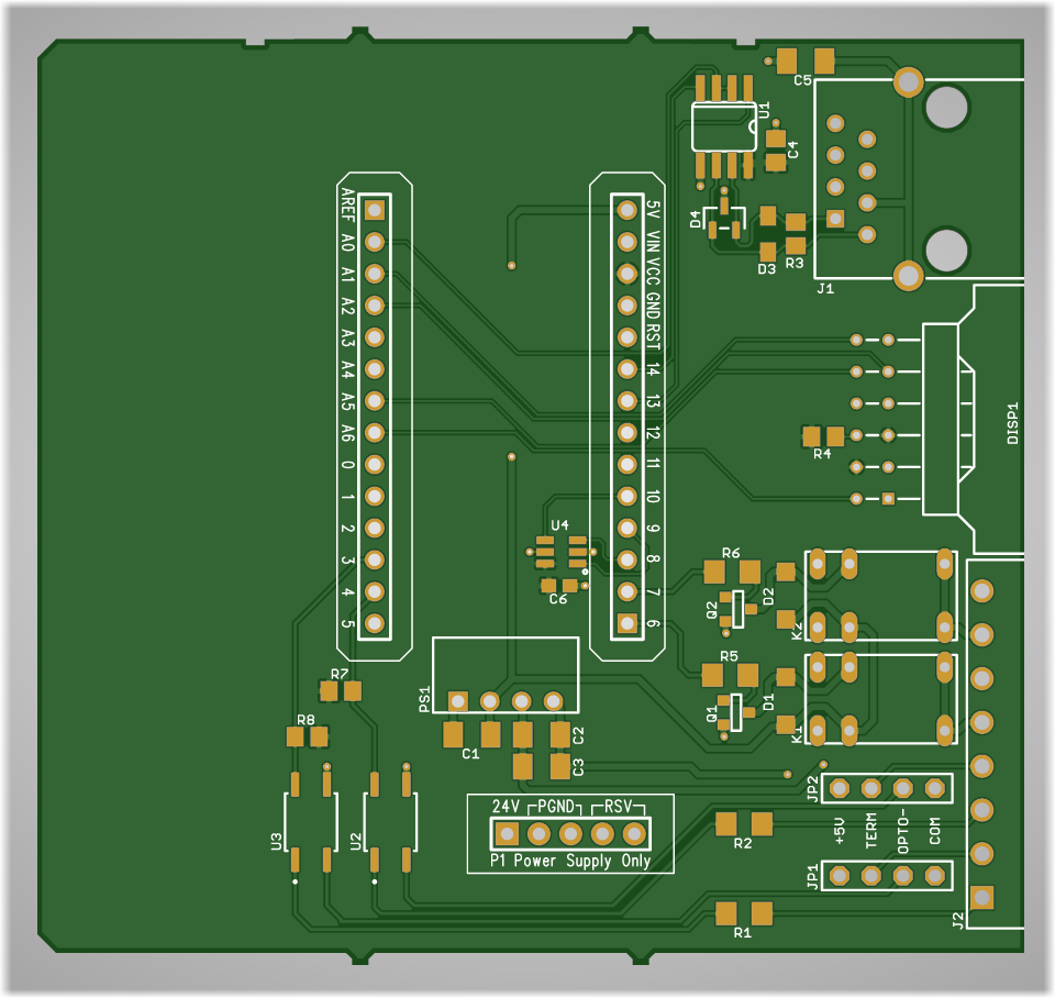
Completed board design.
Once the schematic was finished, I turned my attention to the board design. The completed board design is shown in the image above. It’s nothing too complicated but fitting components around the MKR headers was a bit tougher than expected. I also had to avoid putting any through hole component leads inside the keep outs on the bottom of the board. Any leads or components in the bottom keep out regions would interfere with the sliding latches that lock the enclosure to the P1AM-100 CPU or other modules.
Manufacturing the Board
After creating my Gerbers, I previewed them using a free online Gerber viewer.
Top View
Top view of the completed board.
Bottom View
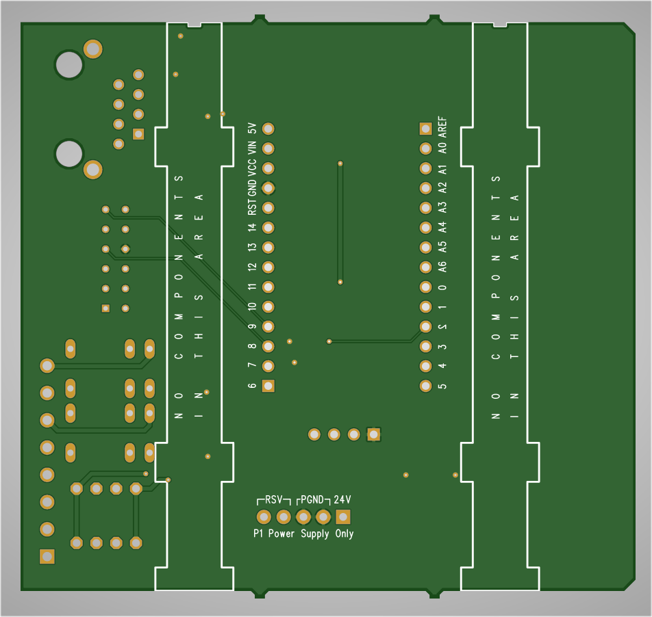
Bottom view of the completed board.
X-ray View
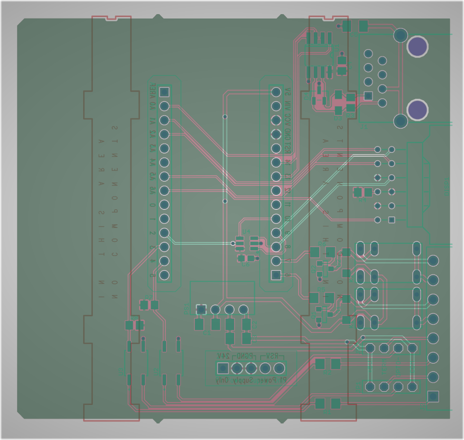
X-ray view of the completed board.
The online Gerber viewer did catch a small problem with the board outline. Because of numerical accuracy issues when importing the Gerbers, two line segments didn’t begin and end on the exact same point and technically the outline wasn’t a closed path. I fixed this issue in the library, updated GitHub with the new library, updated my boards, and created new Gerbers. This time I was happy with the previews and ordered the boards.
Finished Boards
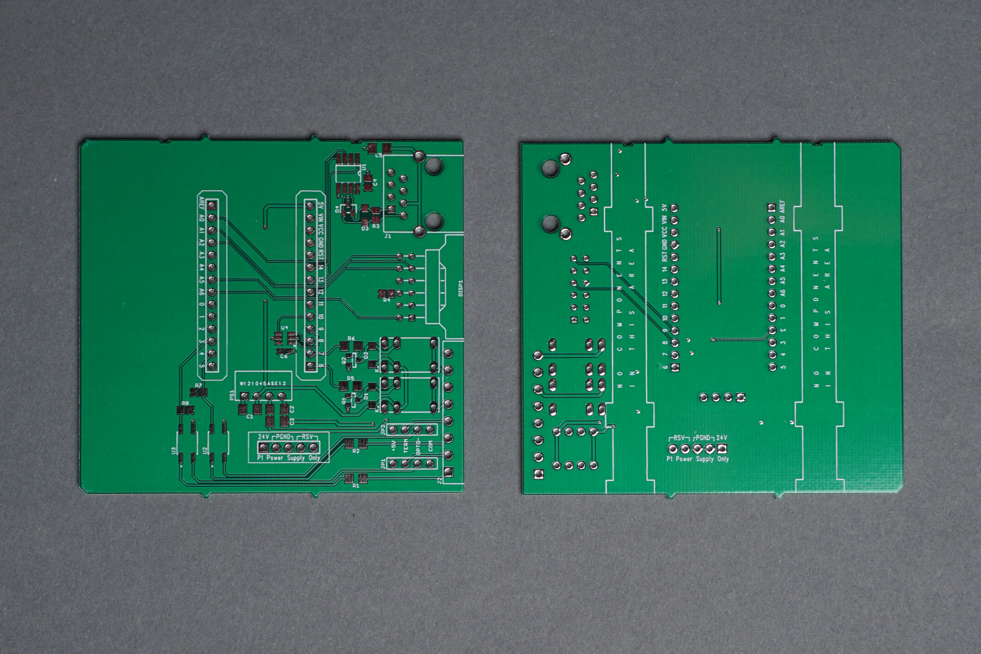
The finished, unpopulated boards.
Above is a photo of the finished boards. I immediately verified that they fit in the prototype enclosure correctly and they did.
Populating the Board
Populated board. The serial EEPROM arrived a week later and was eventually soldered in too.
The next step was to populate the board. I populated the board by hand using a pretty big chisel soldering iron, quality lead-free tin/silver/copper solder, and lots of paste flux. The socket for the display is a bit shorter than the display is tall so I plugged the display into the socket and soldered the socket a bit higher above the board than where it normally would land.
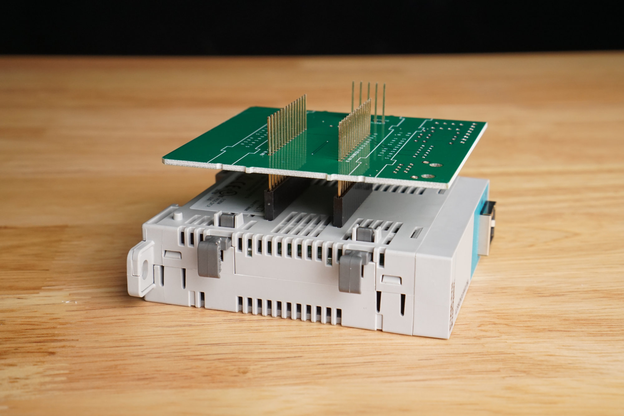
Technique to solder headers on to board.
The header sockets were a bit difficult to solder but one of the Automation Direct / FACTS Engineering engineers suggested in their forums to mount the sockets on an existing module, placing my board on the pins, then soldering the header sockets. This helped immensely. See the photo above.
Hardware Test

Photo of my prototype module undergoing hardware test.
Once the boards were populated, it was time to test them. I wrote some quick software to drive the display, read the serial EEPROM, read the isolated inputs, control the relay outputs, and drive a DMX-512 light fixture using the RS-485 interface. This allowed me to test all the hardware except the RS-485 receive function.
I also wrote code to use the Ethernet module and micro SD card and exercised them while testing the hardware. This let me verify that none of my hardware interfered with their operation. I did not test the use of P1000 bus modules or the real time clock.
Example Application: Garage Overhead Light Controller
For an example application, I decided to write some software to control the overhead lights in my garage based on the state of the garage door. Here are the requirements for the software:
- At startup:
- Initialize the hardware.
- Display “Hello, world!” on the LED display.
- Read the Ethernet MAC address from the serial EEPROM.
- Display the Ethernet MAC address on the LED display.
- Initialize the P1AM-ETH hardware with the Ethernet MAC address and get an IP address and DNS server via DHCP.
- Once the Ethernet hardware is ready, display the IP address and DNS server on the LED display.
- While idle:
- Move a dot around on the LED display to indicate that the software is still running.
- When the garage door is opened:
- Display “Garage Door Opened” on the LED display.
- Send a message over the network to an Insteon controller to turn on the garage overhead lights.
- Send a message over the network to a custom board to turn on an industrial stack light inside the house to indicate the door is open.
- Turn on the P1AM-100’s builtin LED to indicate the door is open.
- When the garage door is closed:
- Display “Garage Door Closed” on the LED display.
- Start a five minute timer.
- While the timer is running, display the time remaining on the LED display.
- After the timer expires, send a message over the network to an Insteon controller to turn off the garage overhead lights.
- Send a message over the network to a custom board to turn off an industrial stack light inside the house to indicate the door is closed.
- Turn off the P1AM-100’s builtin LED to indicate the door is closed.
All these things can be done on the local network without encryption and were successfully implemented. Rather than dive into the code here, I’ll let the (lack of) comments in the source code speak (or not) for themselves. The Arduino sketch for the project is on GitHub. Let me know if you have questions on Twitter @bikerglen and I’ll try my best to answer them.
I initially wanted to send a message to the IFTTT maker channel to indicate the state of the door and to send a text message when the door was opened using Twilio but these tasks require SSL/TLS and basic authentication. There is an SSLClient library for the ATSAMD21 and Arduino. I may look into using it at a later date.
Hardware and Software Design Files
The hardware and software design files as well as the Eagle PCB library for a board to fit the prototype enclosure are located in this GitHub repository. This project is in the p1am-isolated-2×2-gpio subdirectory.
The software in the repository includes both applications. The first application is for testing out all the hardware and is a good starting point for seeing how to control different parts of the hardware. The second application is the garage door monitor application described above and demonstrated in the YouTube video.
Next Projects
My next two projects are a full-duplex RS-485 board with similar functionality to the Arduino MKR 485 Shield and a board to add DMX-512 lighting control and sound effects to a Halloween prop controller built on the P1AM-100 with a few P1000 bus modules. Stay tuned!