
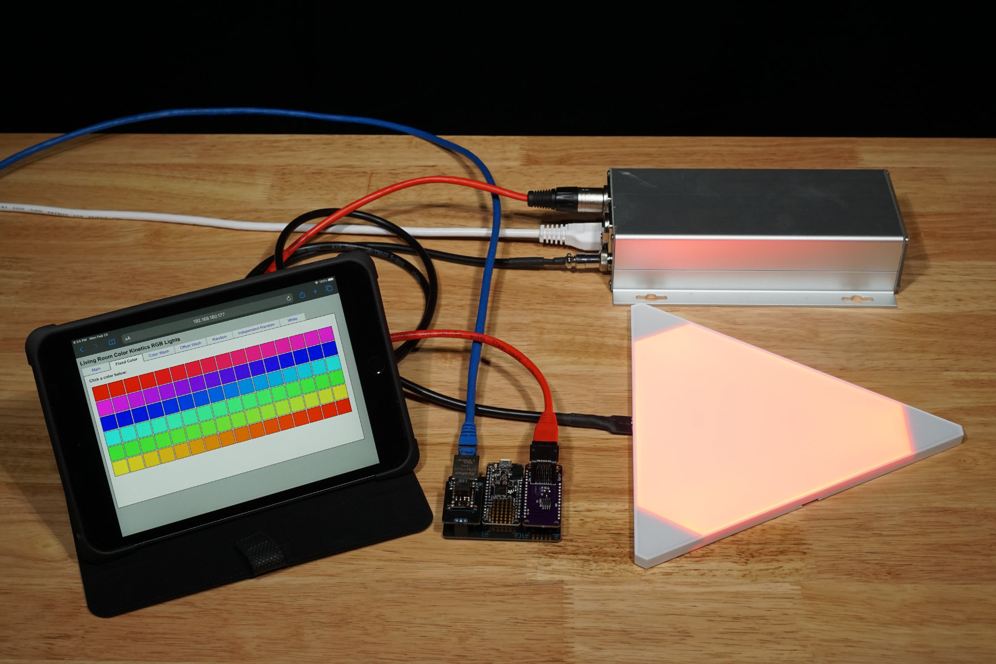
Playing around with the DMX FeatherWing, a Particle Ethernet FeatherWing, an Adafruit Feather M0 Basic Proto, the official Nanoleaf DMX interface, and a Nanoleaf Aurora tile. The GUI on the iPad tells the Feather M0 which light program to run. The program output is sent via DMX-512 to the Nanoleaf setup.
This project uses an Adafruit Feather M0 Basic Proto board to control a group of Color Kinetics or other RGB light fixtures using the DMX-512 protocol. We’ll build a DMX-512 interface FeatherWing then connect it to the Feather M0 using a Particle Ethernet FeatherWing. Once the hardware is built and assembled, we’ll write software with a web-based GUI to generate RGB lighting effects and control the attached RGB lights using the DMX protocol. By modifying the software on the Feather M0, different effects can be generated and added to the web-based GUI.
Required Materials
The materials required for this project are:
- DMX FeatherWing board and parts. We’ll discuss ordering the board, the required parts, and the assembly in the next section.
- Adafruit Feather M0 Basic Proto
- Particle Ethernet FeatherWing
- Particle Ethernet FeatherWing PoE Adapter (optional). Note: The PoE adapter has been discontinued. If you want to make your own version, the Eagle design files are available here but the header sockets on the module need to be moved to align with the headers on the Ethernet FeatherWing board.
The DMX FeatherWing
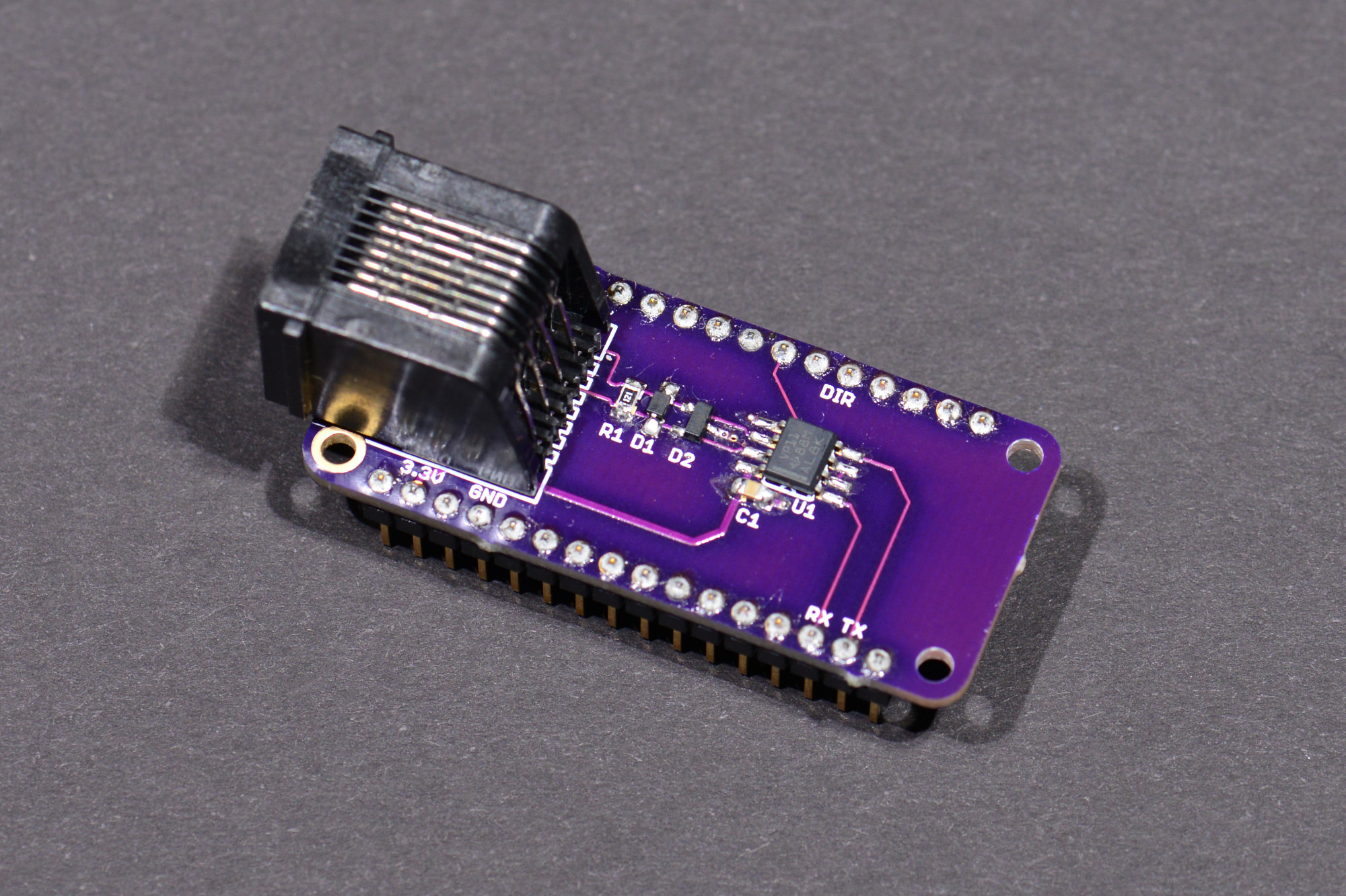
The assembled DMX FeatherWing board. I fixed the location of the DIR silkscreen label in the Eagle design files and on the board order link at OSH Park.
The photo above shows the assembled DMX FeatherWing. The next few sections are dedicated to describing and building the DMX FeatherWing hardware.
Circuit Design and Schematic
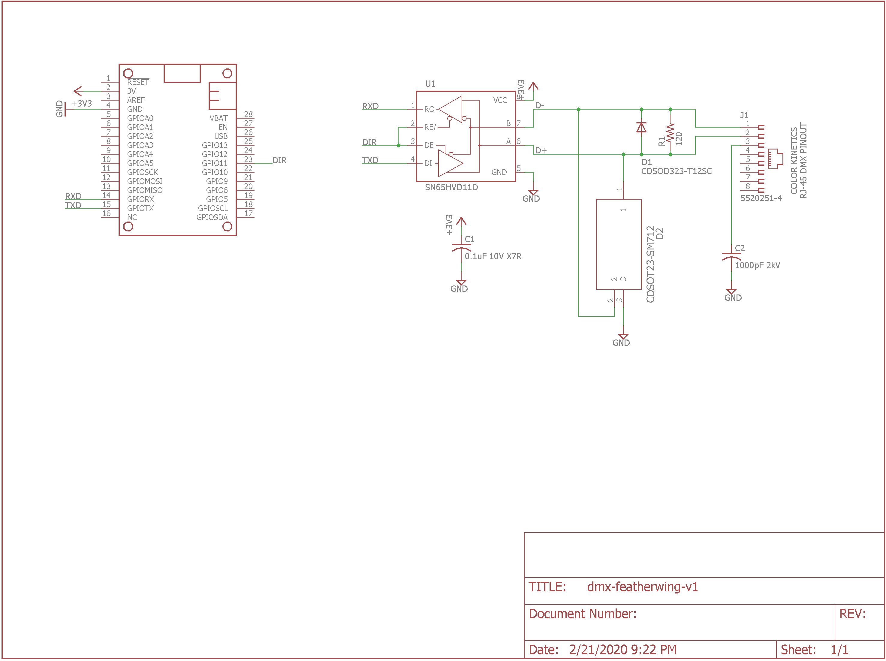
DMX-512 FeatherWing schematic.
To make sure everything conformed to the FeatherWing form factor, I started with the Eagle design for the Adafruit Power Relay FeatherWing. I deleted everything from the schematic and board except for the FeatherWing symbol and dimension lines. The FeatherWing symbol includes the board outline layer and the holes for the 0.1″ pitch, 0.025″ square post headers that connect the FeatherWing to other boards. I saved this as a new file then started my design.
U1 is a Ti 3.3V differential transceiver. Its transmit data input is connected to the Feather’s transmit data output pin. Its receive data output is connected to the Feather’s receive data input. The direction line is connected to a GPIO pin. I only plan on transmitting data so I could have tied the direction pin high to permanently enable the transmitter and disable the receiver but connecting it to a GPIO allows me to control the direction in software and could be useful for future projects.
J1 is a plastic RJ-45 8P8C jack. It’s wired to connect to Philips Color Kinetics’ lights and controllers. Other DMX lights with RJ-45 jacks may use different pin outs. Typically pins 1 and 2 are swapped or the shield is on a different pin on these lights. R1 is the 120 ohm termination resistor required at the transmitter by the DMX specification. Another 120 ohm termination resistor should be placed at the last fixture in the chain of fixtures.
The rest of the parts are for decoupling, EMC compatibility, and ESD protection. C1 is a decoupling capacitor to filter voltage transients on the supply to the differential transceiver. C2 grounds high frequency noise on the shield line while preventing a DC current loop between the board and any connected light fixtures. This should help with EMC compatibility but still provide isolation between the hardware at either end of the DMX cable.
D1 and D2 provide additional ESD protection beyond the ESD protection built into the differential receiver. Their function is described in the TI application note Protecting RS-485 Interfaces Against Lethal Electrical Transients.
Board Design
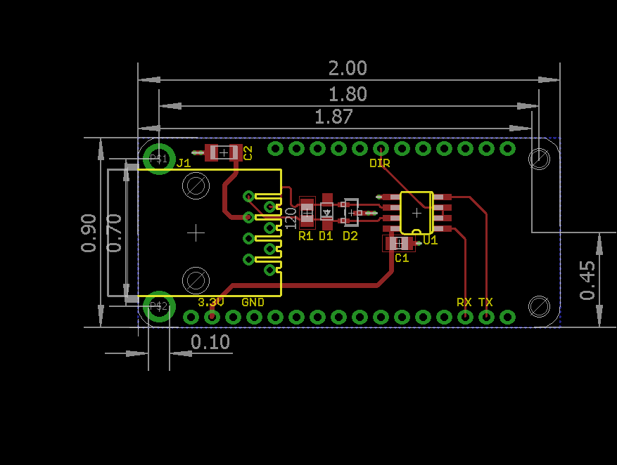
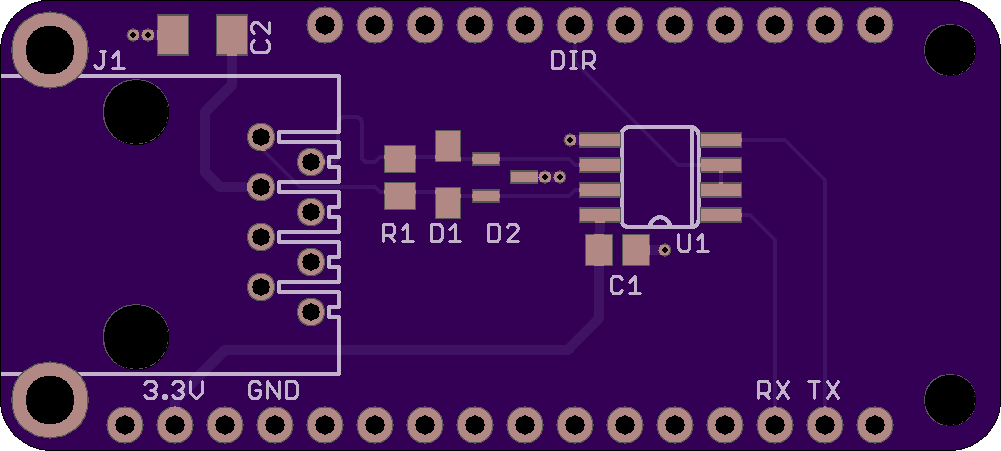
DMX-512 FeatherWing board design.
Components were placed on the board to minimize the length of the signal traces. The differential data lines between J1 and U1 contain a small loop to equalize their lengths. The termination resistor and ESD components connect straight from these pins to the pins on the differential transceiver. C1 is located as close as possible to U1’s 3.3 V supply line. The direction, transmit data, and receive data lines are routed to the FeatherWing headers.
DMX-512 FeatherWing top side board render.
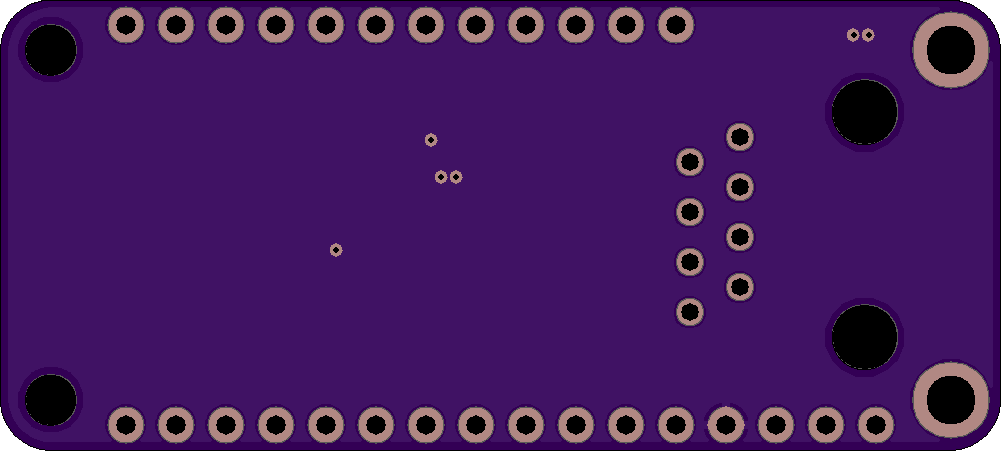
DMX-512 FeatherWing bottom side board render.
Once the board design was done, I uploaded the Gerber files to OSH Park and checked the renders to make sure everything looked OK. Once I was happy, I ordered the boards from OSH Park.
Ordering Boards
If you wish to use the board exactly as designed, you can order a blank board from OSH Park here. If not, you can download the Eagle design files from Github, make your desired modifications, create Gerbers, and order boards from your favorite PCB manufacturer. My top and bottom silkscreens are located on layers 121 and 122 respectively so you may need to alter your CAM processor script to output these layers to the silkscreen Gerber files.
Bill of Materials
The bill of materials is available in the Github repository as an Excel spreadsheet. It’s also reproduced below for your convenience. All the parts are available from Digi-Key.
| Qty | Parts | Description | Mfr | Mfr Part # | Digi-Key Part # |
| 1 | C1 | CAP CER 0.1UF 10V X7R 0805 | Kemet | C0805C104K8RACTU | 399-7999-1-ND |
| 1 | C2 | CAP CER 1000pF 2KV 10% X7R SMD 1206 | Johanson Dielectrics | 202R18W102KV4E | 709-1036-1-ND |
| 1 | D1 | TVS DIODE 12V 29.5V SOD323 | Bourns Inc. | CDSOD323-T12SC | CDSOD323-T12SCCT-ND |
| 1 | D2 | TVS DIODE 7V/12V 14V/26V SOT23-3 | Bourns Inc. | CDSOT23-SM712 | CDSOT23-SM712CT-ND |
| 1 | J1 | CONN MOD JACK 8P8C R/A UNSHLD | TE Connectivity | 5520251-4 | A31407-ND |
| 1 | R1 | RES SMD 120 OHM 5% 1/8W 0805 | Panasonic | ERJ-6GEYJ121V | P120ACT-ND |
| 1 | U1 | IC TRANSCEIVER HALF 1/1 8SOIC | Texas Instruments | SN65HVD11DR | 296-31717-1-ND |
| 1 | — | CONN HEADER VERT 50POS 2.54MM | Samtec Inc. | TSW-150-07-G-S | SAM1029-50-ND |
DMX FeatherWing Assembly
To assemble the board, solder all the surface mount components first starting with U1. Once the surface mount components are soldered, solder the headers to the bottom of the board. It can be helpful to place the headers in a breadboard to hold them in place while soldering them to the DMX FeatherWing. This technique is described in detail on Adafruit’s website here. Finally, insert the RJ-45 connector into the top of the board, flip the board over, and solder the connector in place.
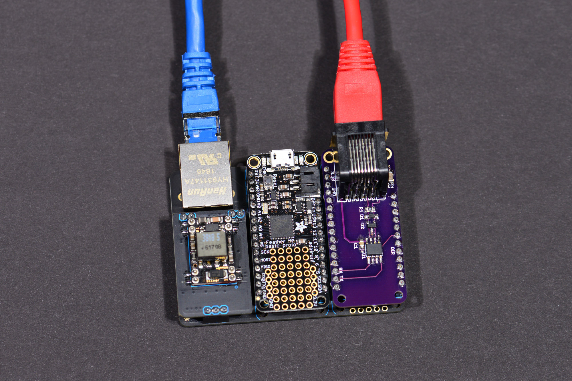
Assemble the Board Stack
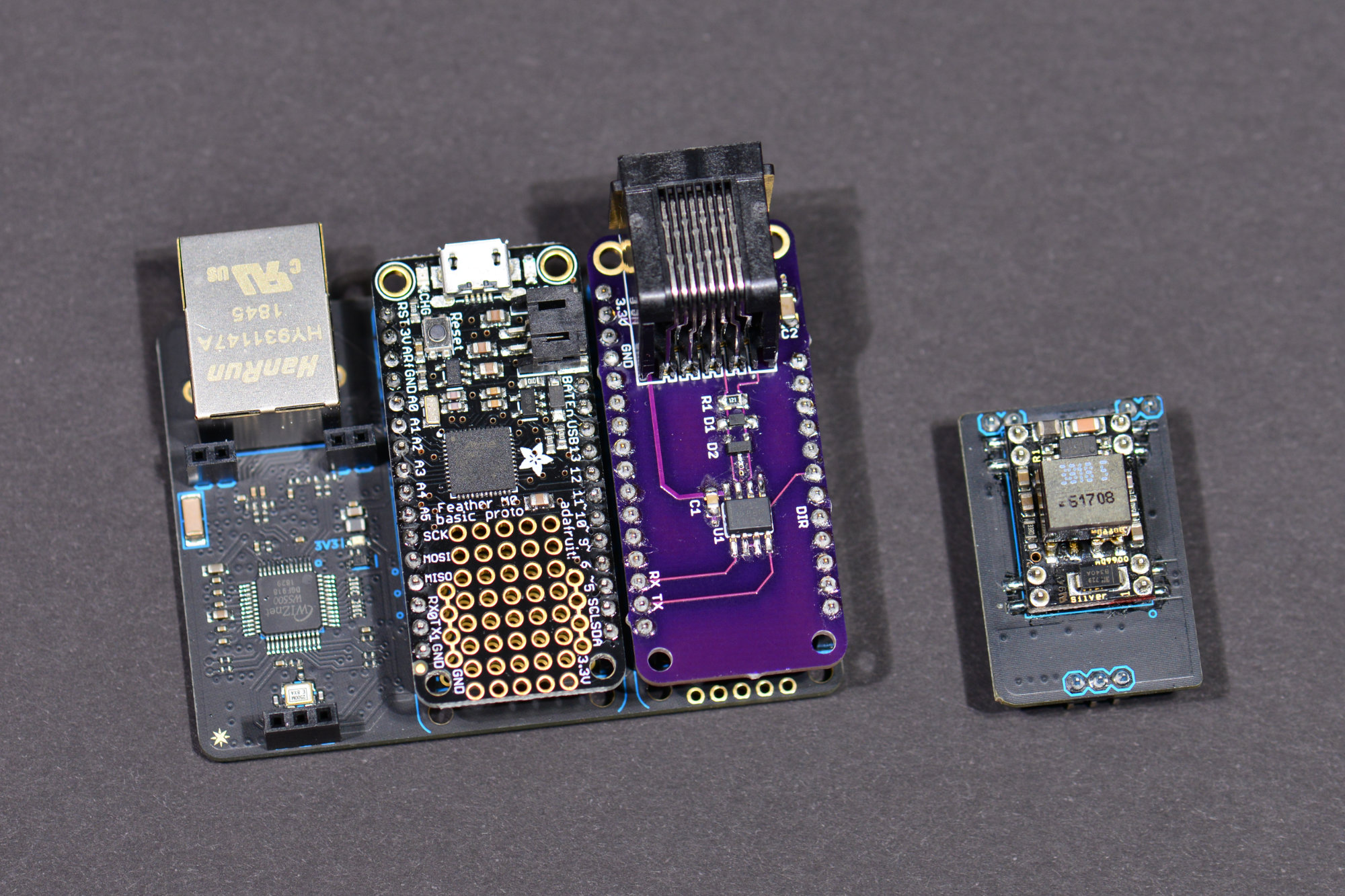
The assembled stack of boards. Do not connect the PoE module at this time.
Once the DMX FeatherWing is assembled, it’s time to connect all three boards together. Holding the Particle Ethernet FeatherWing board with the Ethernet circuitry on my left, I placed the Adafruit Feather M0 Basic Proto in the middle of the board and the DMX FeatherWing on the right of the board. If you have the optional PoE module, do NOT install it at this time!
We’re going to be using the USB cable to power the stack of boards and download software to the ATSAMD21. Powering the boards from both the PoE supply and the USB cable can result in damage to your boards and/or your computer. Never use both the PoE module and the USB cable at the same time.
Install Software Environment and Libraries
This project uses the Arduino integrated development environment for the Adafruit Feather M0 Basic Proto. Follow the instructions on the Feather M0 Basic Proto tutorial page to install the Arduino IDE and additional boards manager URL. Once those are installed, install the libraries required for the Feather M0 boards and the ATSAMD21 as instructed on the next page of the same tutorial.
This project also uses the Arduino Ethernet and Timer libraries. Follow these instructions to install the Ethernet library. After installing the Ethernet library, install the Arduino Timer library. It’s the same process as for the Ethernet library except search for the arduino-timer library by Michael Contreras v2.0.1. Once you’ve found it in the GUI, install the library and perform one last restart of the Arduino IDE.
Test the Software Installation
I recommend testing the software installation by building and running the WebServer example for the Ethernet library. In the Arduino IDE, click Tools -> Board -> Adafruit Feather M0. Once the board is selected, click on File -> Examples -> Ethernet -> WebServer to open a new window with the example WebServer project. Be sure to pick Ethernet and not Ethernet2.
Now select File -> Save As to save a copy of the WebServer example in your Arduino projects directory. Find the IPAddress ip (…) line and change the IP address to a valid static IP address for your network. Finally uncomment the line Ethernet.init(10) to pick the correct chip select for the combination of the Particle Ethernet FeatherWing and Adafruit Feather M0 Basic Proto boards.

The boards set up to download and test the code.
Connect the RJ-45 Ethernet jack to an Ethernet switch on the same network as your computer. Make sure the optional PoE module is NOT installed then connect the micro USB connector on the Feather M0 board to a free USB port on the computer.
Go to Tools -> Port and select the COM port connected to the Feather M0. Now launch the serial monitor by selecting Tools -> Serial Monitor. Finally build the example and download the code to the board by selecting Sketch -> Upload in the Arduino IDE.
If everything is successful, you should see something similar to the following in the serial monitor window:
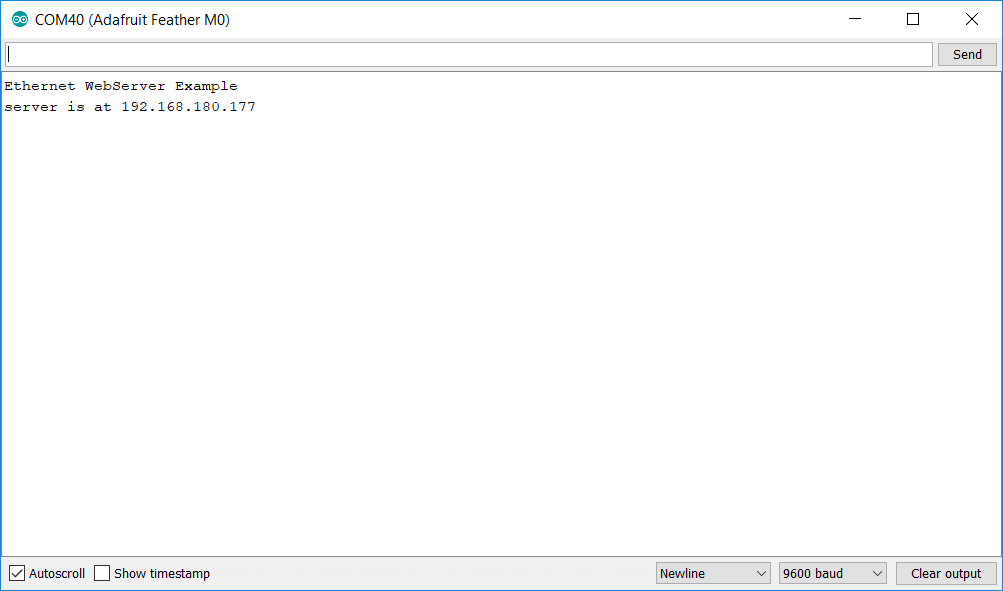
Build and download success!
Use your favorite web browser to navigate to the specified IP address. You may need to prepend http:// to the IP address for some browsers. You should get something similar to the following:
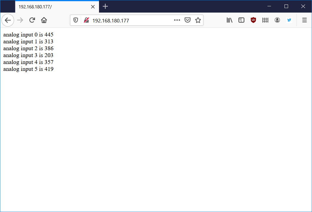
Web server test successful!
And the serial monitor will update with some debugging info every time the browser is refreshed:
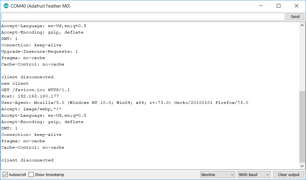
The serial monitor after sending a web page to the web browser.
At this point, the test is successful and it’s time to try to control some lights with the real software.
Connect Some RGB DMX Lights
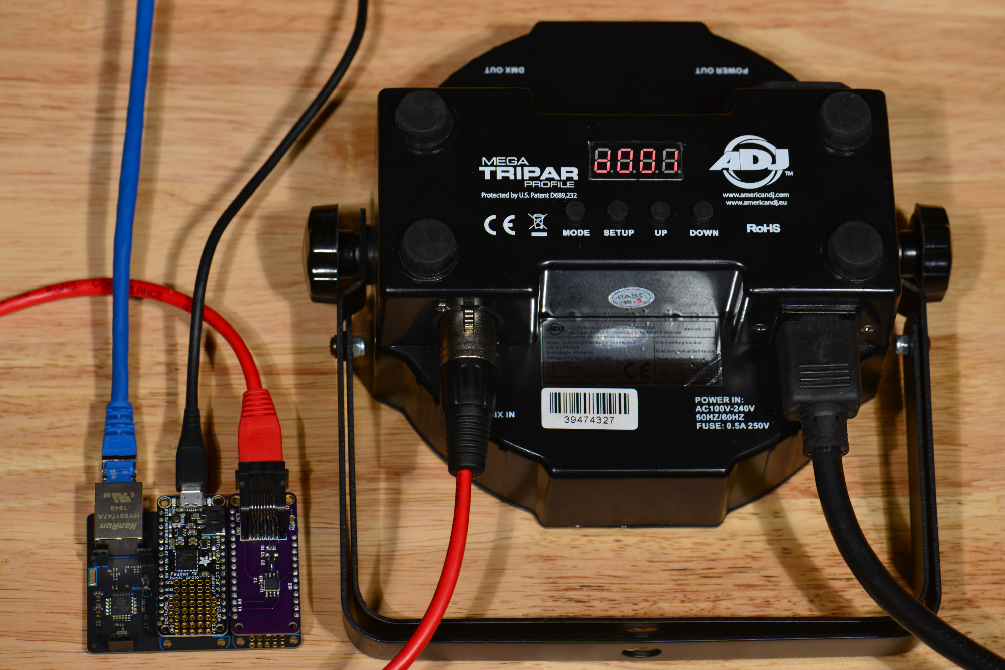
An inexpensive light like this one with a homemade RJ-45 to XLR 3-pin adapter cable makes a good fixture for testing the hardware and software.
Connect some RGB DMX lights to the DMX FeatherWing’s RJ-45 jack. The software in its default configuration controls 24 RGB lights using DMX channels 1 to 72. Make sure your connected lights are in this range and the red channels start with 1, 4, 7, etc.
Download and Run the DMX Controller Software
Download the DMX Controller Source Code from Github
My latest DMX controller software can be downloaded from Github here. Download these files into a new folder. This folder must be named dmx-controller and must be inside the Arduino projects folder. This is a constraint of the Arduino IDE.
Set the IP Address
Just like for the example WebServer project, the IP address must be set to a valid static IP address for your network. Find the IPAddress ip (…) line in the dmx-controller.ino file and set it to a suitable IP address.
Build and Download the Code to the Feather M0
If the serial monitor window is not already open, open it again by selecting Tools -> Serial Monitor. Now build and download the code by selecting Sketch -> Upload.
Using the Web Interface
Enter the IP address from above into your favorite web browser and you should get the following web page:
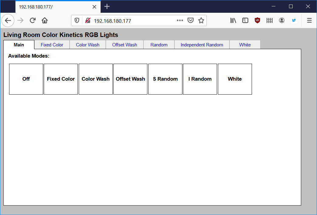
Opening page of the web-based GUI for controlling the attached lights.
Now click the Fixed Color tab. The web page will update to display this screen:
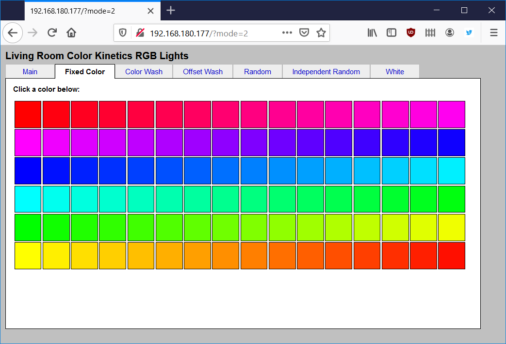
Fixed color tab.
Clicking on a color should change the color of the connected lights to the selected color. Once this is working, experiment with some of the other tabs and settings.
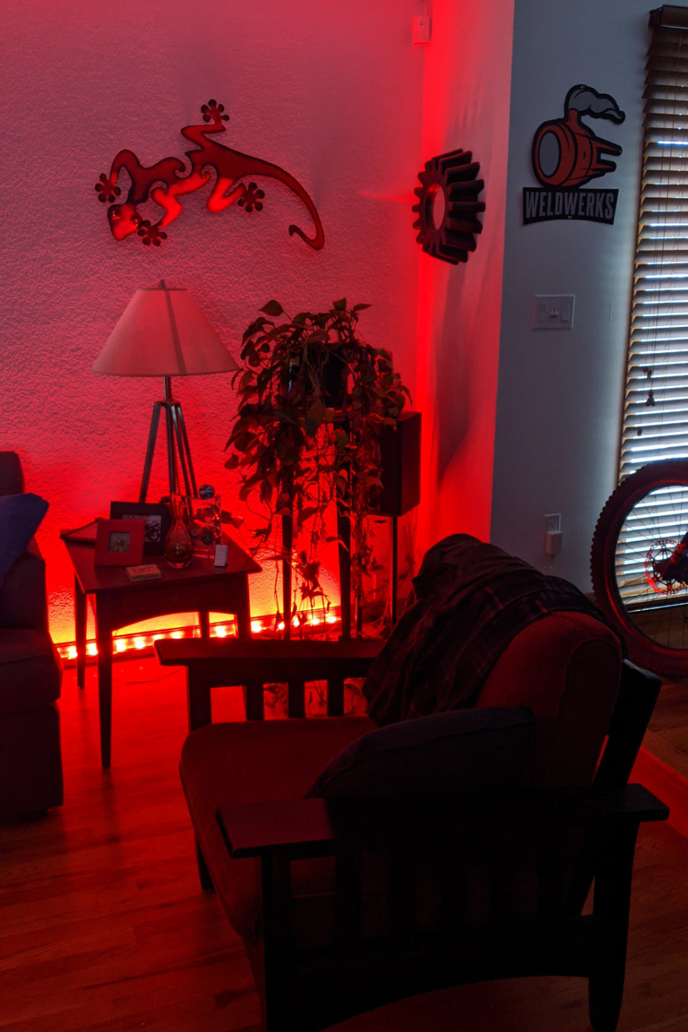
My living room wall washed in red light using the fixed color mode on the controller.
Congratulations if you’ve made it this far! At this point the project works. The following sections are for those who wish to dive deeper into the controller’s functionality or modify the software or hardware.
Software Details
Sending DMX Data with the ATSAMD21
To send DMX-512 data with the ATSAMD21 microcontroller, I used the LXSAMD21MDX library by Claude Heintz as a starting point. Unfortunately, this library sends DMX data continuously so as soon as a packet is done being sent, it immediately starts sending the next packet.
This causes a problem because there’s no way to guarantee that I won’t update the RGB values for a light in the middle of those values being sent. For example, if I were updating the RGB values for a light and the library sent the new red and new green values before I could update the blue value, this could cause a light to flash a wrong color for a brief instant.
Next I tried stopping the DMX transmission using the stop function in the library. Calling this function completely disabled the serial port and, as a result, the transmit data line was no longer driven. This caused a very long low / break signal to be transmitted between packets which is against the DMX-512 specification that requires the line to be held in the high / mark state between packets.
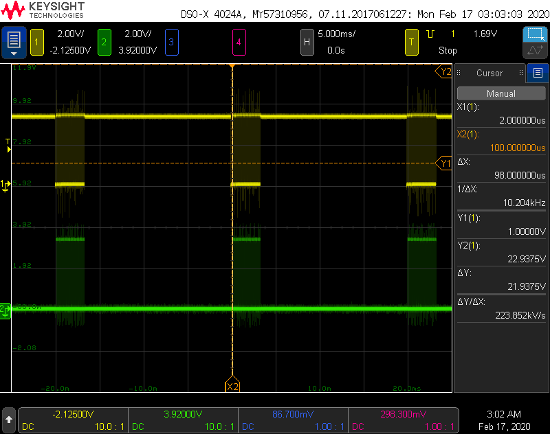
Screen capture from my scope. The yellow trace shows DMX packets being transmitted at 50 Hz (20 ms between the start of each packet). The transmit data line is held high between packets which is the idle state for the serial interface. The green trace was connected to a GPIO that was set upon entry to the SERCOM2 interrupt handler and cleared upon exit.
I decided to rewrite the DMX library and to use a double buffering scheme. The light levels are calculated and stored in an effects buffer. When it’s time to send a packet, the light levels are copied from the effects buffer to a transmit data buffer. The library is then called to transmit a single DMX packet using the values in the transmit data buffer.
While the DMX packet is being sent, the effects generation code is called to generate the next set of light levels and store them in the effects data buffer. This happens at a 50 Hz rate and completely prevents partially modified data from being sent to the lights. I used a scope to verify the packet rate, the DMX-512 break period, and the bit rate on the interface.
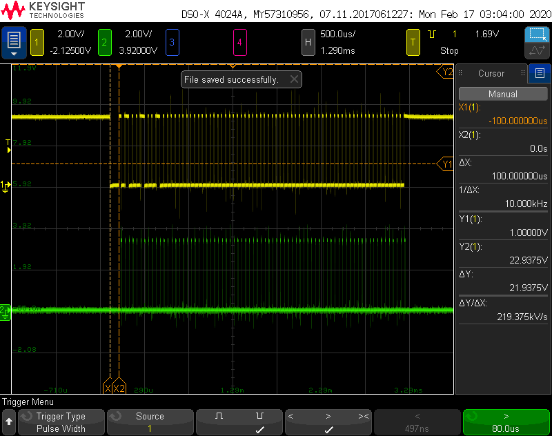
The DMX packet starts with a break of 100 us (yellow trace). This is much longer than a normal 250,000 bps break character. The scope was set to trigger on a negative pulse with a pulse width greater than 80.0 us. The green trace was connected to a GPIO that was set upon entry to the SERCOM2 interrupt handler and cleared upon exit.
While I was prototyping the project, I left the microcontroller’s receive data pin unconnected. This resulted in the microcontroller receiving errored characters and generating both receive character and error interrupts. Since I wasn’t expecting or handling these interrupts, this resulted in the microcontroller being stuck in the interrupt handler.
I traced the cause of this behavior to the begin method in the Arduino Uart class which enables the receive character and error interrupts. I disabled these interrupts by adding the following code immediately after calling the Uart class’s begin method and everything started working:
     SERCOM2->USART.INTENCLR.reg = SERCOM_USART_INTENCLR_RXC |
                                 SERCOM_USART_INTENCLR_ERROR;
This likely isn’t an issue with the real hardware because the receive data pin is not left floating. I’m not using the receive portion of the USART, however, so I might as well disable the interrupts to avoid any chance of them causing problems in the future. I could probably even disable the USART’s receiver altogether if I wanted.
Modifying the Built-In Effects or Adding New Effects
Adding a new effect to the code requires defining a new mode, adding some HTML to display the options for the mode, parsing the HTTP request to get the options for the mode, and adding code to run the mode.
effects.ino
The effects.ino file contains code to run the effects and change options associated with each effect. This file requires several additions to create a new mode.
- The enum at the very top of the effects.ino file defines the available modes. To add a mode, add another definition to this enum.
- Scroll down the file a bit and look for the global variables starting with the effects_ prefix. Add any variables to store options associated with the new mode here.
- Inside the effects_Init function, add code to initialize the options associated with the new mode to reasonable default values.
- Inside the effects_Run function, add another case statement to the switch block to call a new function to generate the mode’s effects.
- Under the EFFECTS GENERATORS heading, add a new function to generate the effect. This function should be named the same as the function added in step 4 above. This function will be called once every 20 ms and should use the effects_ global variables added in step 2 to calculate the next step in the effect. The RGB values should then be written to the effects_data array. This array contains DMX_SLOTS values which corresponds to DMX_SLOTS / 3 RGB lighting fixtures.
- Under the COMMANDS FROM UI heading, add any functions that will be called by the HTTP request parsing code to modify the effects_ global variables.
dmx-controller.ino
The dmx-controller.ino file contains the code to parse the HTTP GET request from the web browser. The HTTP GET request is parsed by the ParseRequest function.
- Add any new key value pairs to the long if-else block about half way through this code.
- Add code to call the functions defined in step 6 in the previous section to modify the effects_ global variables under the Set Parameters comment.
html.ino
The html.ino file contains C/C++ code that emits HTML to the web browser to permit the user to change the mode and configure any options associated with the mode. The function SendHtmlPage is the function that is called to emit the HTML.
- Add an additional call to the Tab function with the mode number and name in SendHtmlPage. This creates an additional tab pane for the options for the new mode.
- Add a case statement to the switch block in SendHtmlPage with a call to a function to generate the HTML that fills the options tab for the new mode.
- Add the function called in step 2 above to generate the HTML to the bottom of the file.
style.ino
If you need additional CSS style code, add C code to generate it in the style.ino file.
samd21dmx.cpp and samd21dmx.h
These files send the DMX packets. If you have more than 24 RGB lights or need more than 72 DMX channels, adjust the DMX_SLOTS define in samd21dmx.h.
Next Steps
Here are some ideas for future enhancements to the project.
Use PoE
Once the software is debugged, the USB cable can be disconnected and the boards powered using the optional PoE module.
If you have the PoE module for the Particle Ethernet FeatherWing, now would be a good time to try it out. Disconnect both the USB cable and Ethernet cable from the stack of boards. Install the PoE module then connect the Ethernet cable. Do not connect the USB cable.
After a brief handshake with the Ethernet switch the board should power up and function just like when it was powered using the USB connection to the computer. Just remember never to connect the Feather M0 to a computer using the USB cable while the PoE module is installed.
Add Art-Net Receive
This functionality is left as an exercise to the reader. Since this project has both Ethernet and DMX, it would be possible to re-purpose the project as an Art-Net to DMX converter. In my proposed implementation, the board would send its own internally generated DMX data and packets until it received an Art-Net packet. Each time an Art-Net packet was received, it would output the levels in the Art-Net packet over DMX. After a timeout of around 30 to 60 seconds, the controller would revert back to sending its own DMX data and packets.
Custom Board and Enclosure Design
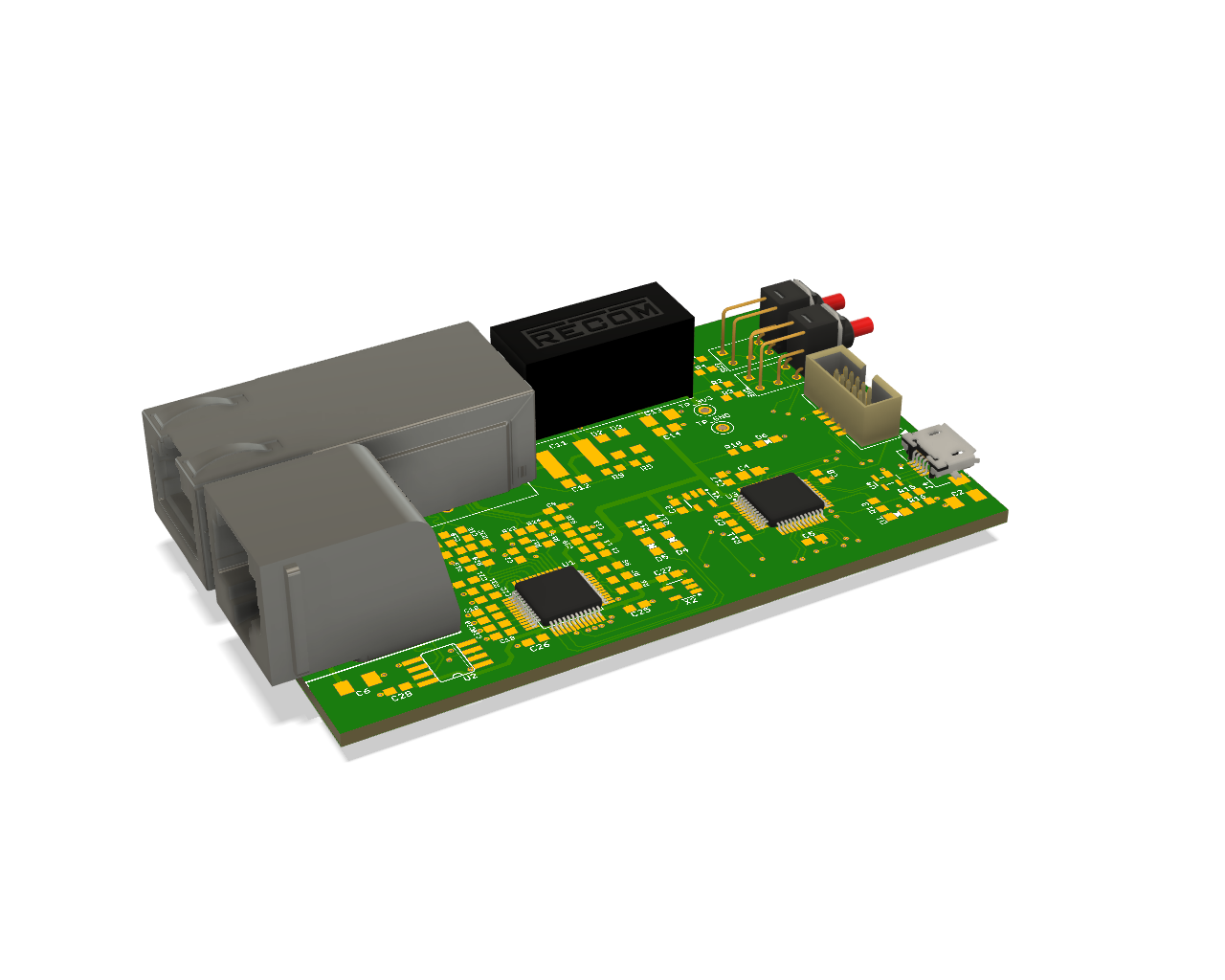
Render of the board design which integrates the functionality of all three boards used in this project.
My personal next step for this project is to build a board that encompasses all the functionality of the three board stack and make it small enough to fit in a Hammond Manufacturing 1455C801 50 mm x 80 mm extruded aluminum enclosure. The render above shows an almost final version of the proposed circuit board. The renders below show the finished enclosure with the board mounted inside.
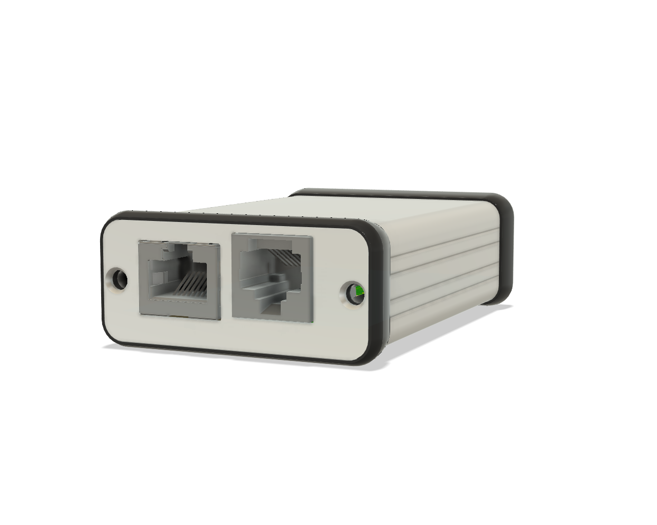
Board mounted inside Hammond Manufacturing 1455C801 extruded aluminum enclosure.
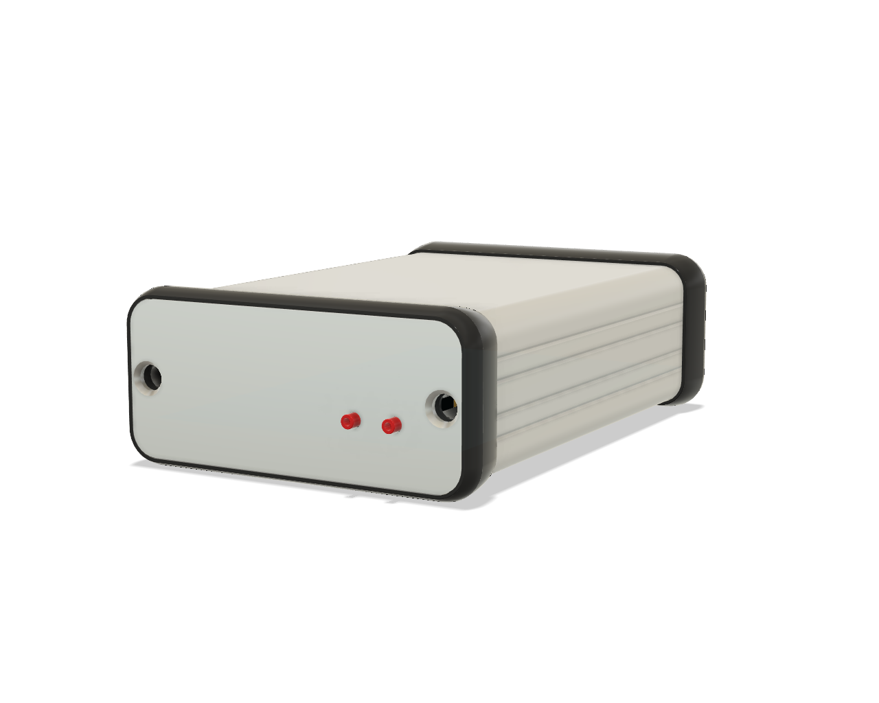
Board mounted inside Hammond Manufacturing 1455C801 extruded aluminum enclosure.
Questions or Comments
If you have any questions or comments about this project, I can be reached on Twitter. In the meantime, stay tuned for updates on the integrated version of this project.