
A brief demo video of the lizard soundboard!
A friend forwarded a video of the lizard slapping the lizard emoji on their phone and I instantly knew I needed to do the same! My phone doesn’t sound out emojis though so I built a single-purpose sound board that does one thing and one thing only: it says Lizard every time you press the button. Follow along to build your own using off-the-shelf electronics and some 3D printing!
Disclaimer: Glen may earn compensation for sales from links on this post through affiliate programs.
The Electronics
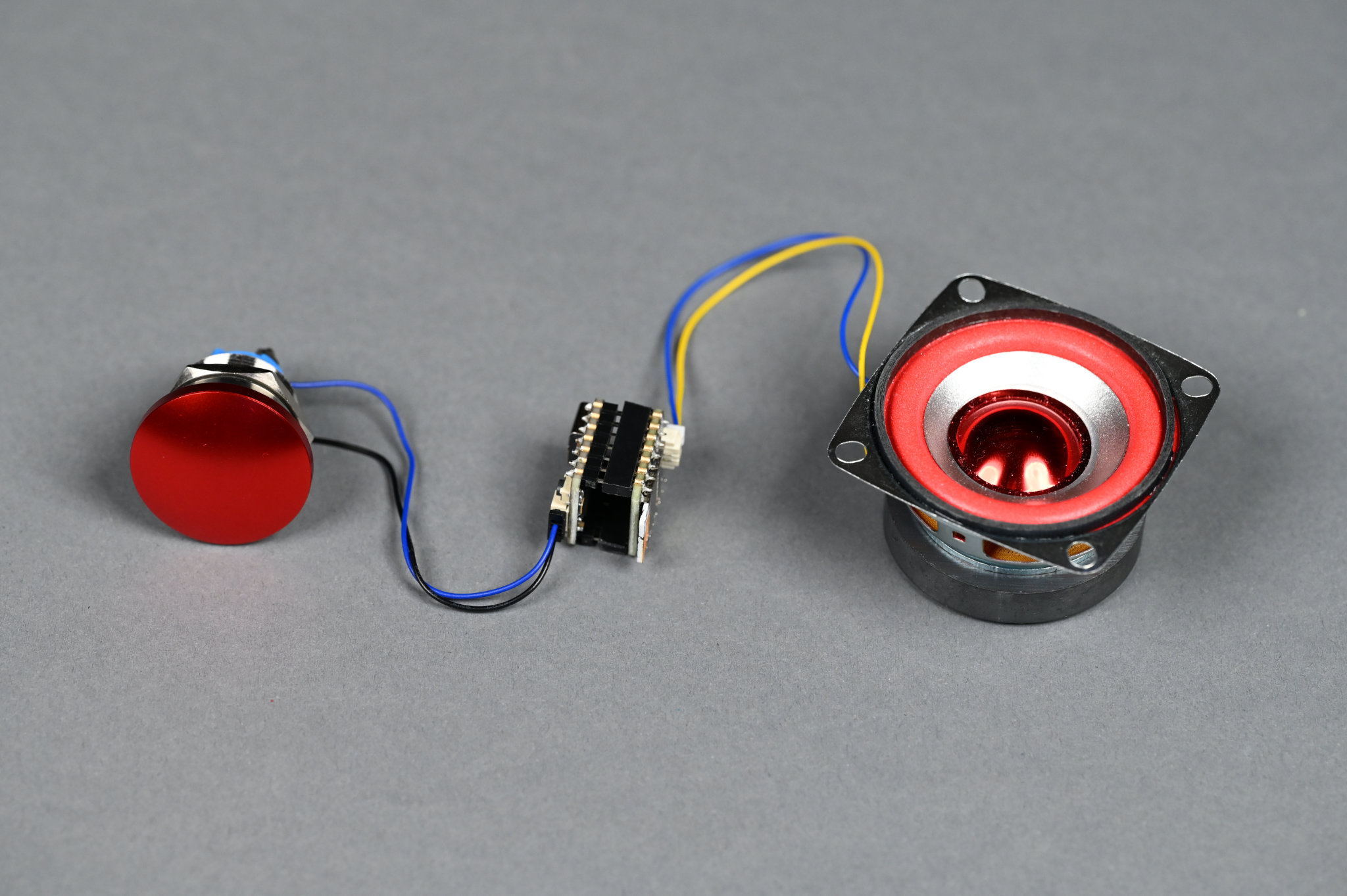
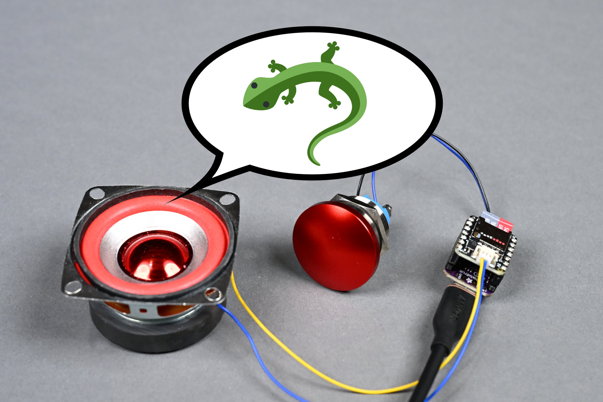
The electronics for the soundboard project.
The electronics for this project are minimal: a button, two dev boards stacked together, a speaker, and an optional microSD card. Basic soldering skills are needed to solder headers and header sockets on the dev boards and wires onto the speaker.
Selecting an Audio Player
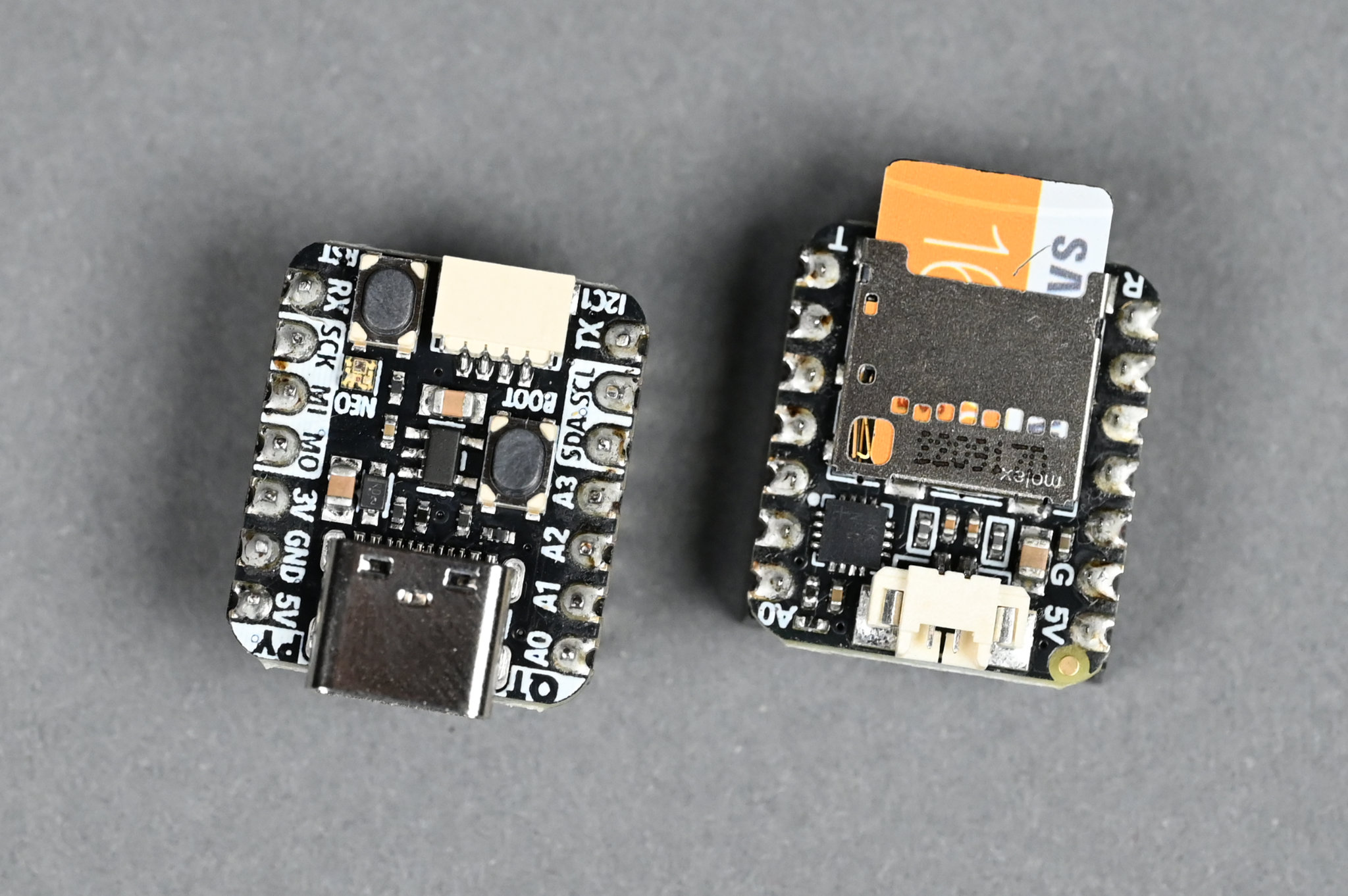
Adafruit QT PY RP2040 and Audio BFF.
For an audio player I chose the Adafruit QT Py RP2040 with the Adafruit Audio BFF Add-on for QT Py and Xiao. This combination offers a micro capable of running CircuitPython for easy code development, a microSD card slot for storing audio samples, an I2S audio DAC, and a built-in 3W mono audio amplifier. This is everything that’s needed to store and play back audio on a small speaker!
If the audio samples will fit entirely inside the QT Py RP2040’s built-in flash storage (8MB minus room for the software), an alternate audio board is the Adafruit I2S Amplifer BFF Add-On for QT Py and Xiao. This board is basically the Audio BFF minus the microSD card slot. If you’re up for a programming challenge and would like to trigger sounds over Wi-Fi and MQTT, the Adafruit QT Py ESP32-S3 board has Wi-Fi and is a drop-in replacement for the RP2040-based board.
Selecting a Speaker
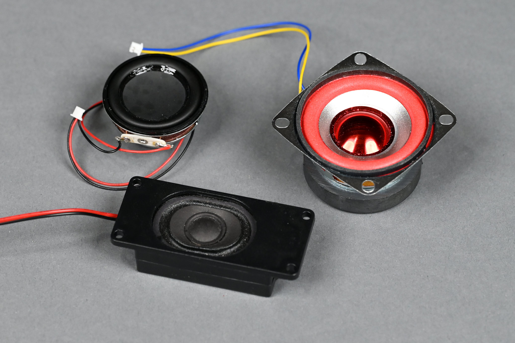
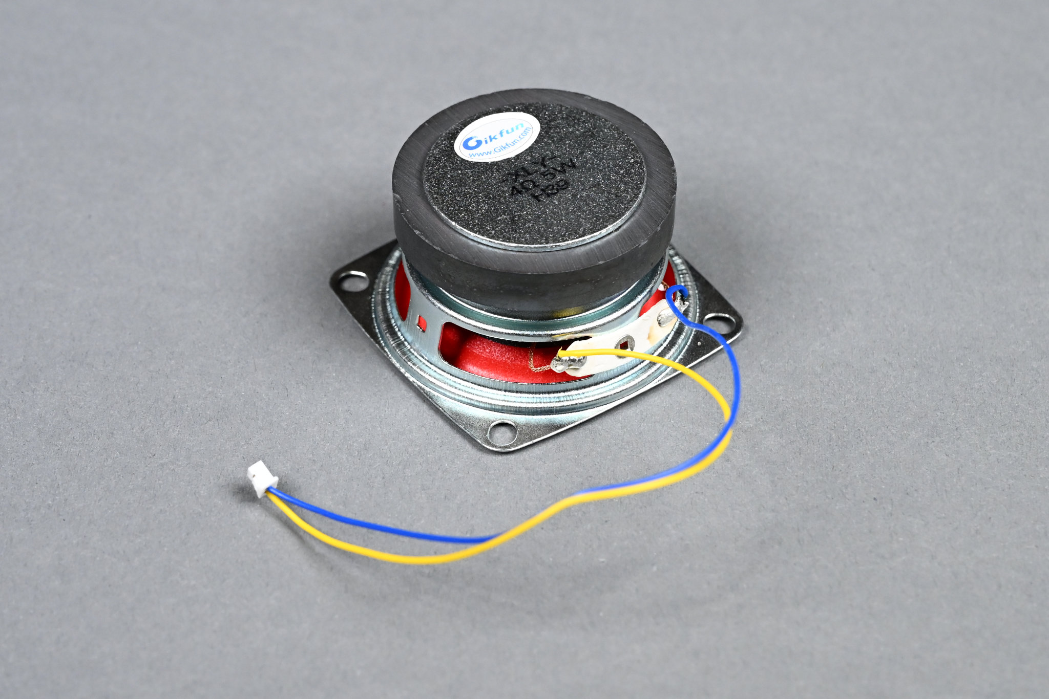
Three candidates for project speaker.
I tried three different speakers before settling on the generic 2″ 4Ω 5W speaker with the red surround and cone. The smaller round one and enclosed oval one are available from Adafruit. I went with the larger speaker because it was the loudest and the mounting holes would make it easy to mount in the enclosure.
Selecting a Button
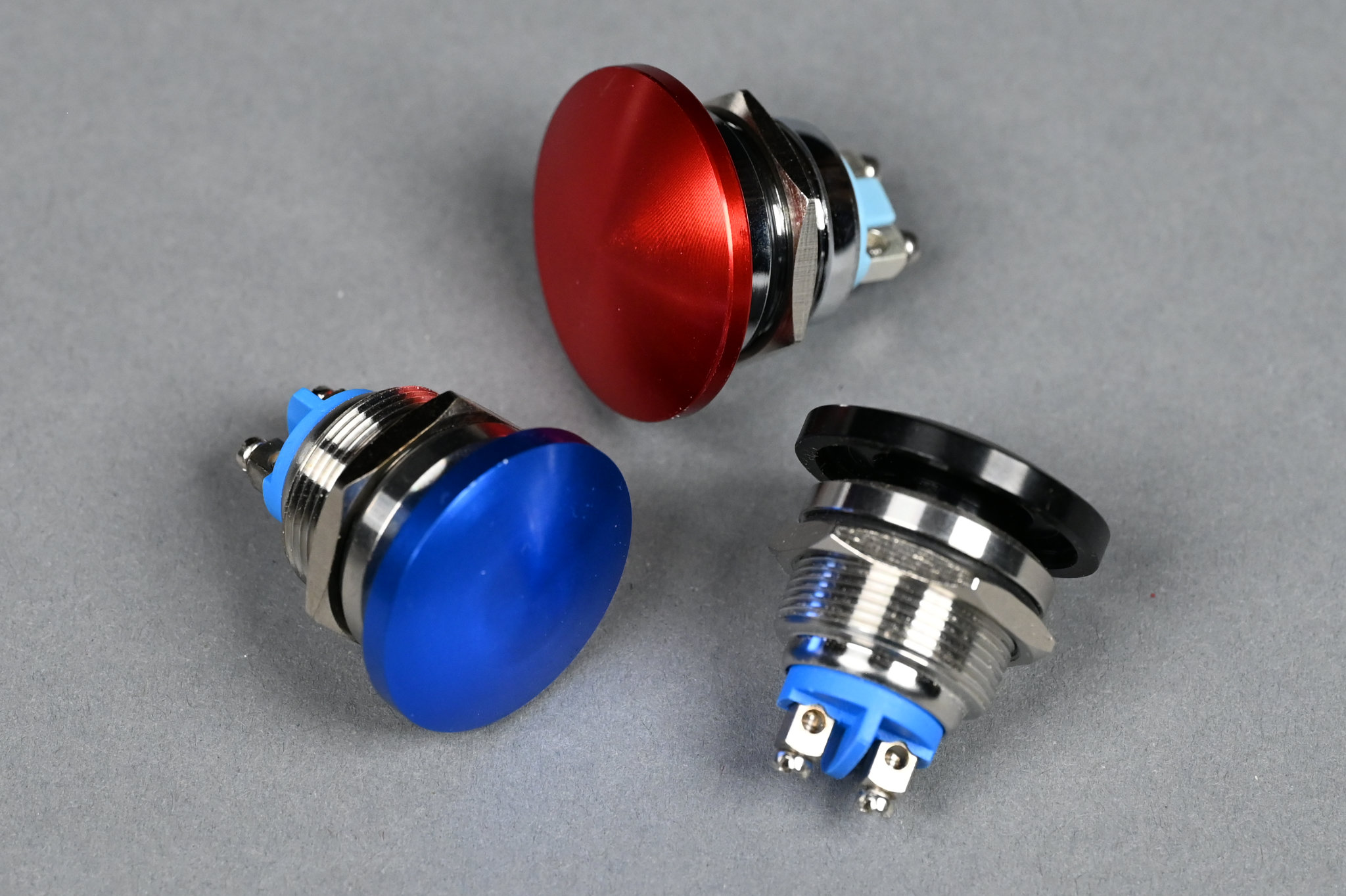
I have a ton of these buttons around the house. Only decision was what color.
The generic buttons shown in the image above are my go-to for cheap push buttons that can easily take modicum of abuse. The screw terminals are convenient too. They’re available under various alphabet soup brand names on Amazon.
Miscellaneous Cables
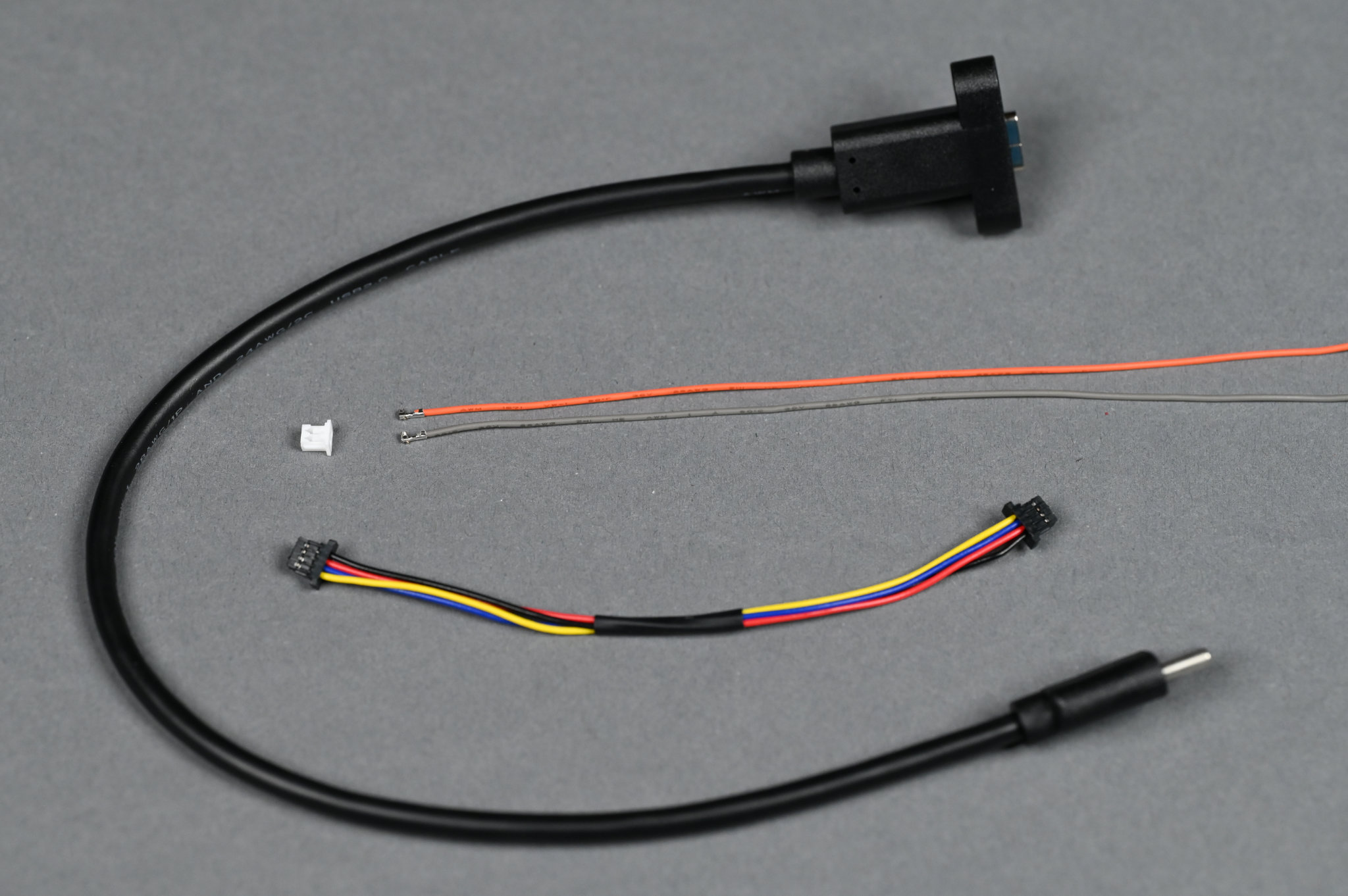
A panel-mount USB C extension, a two pin picoblade connector and pre-terminated leads, and a Qwiic jumper cable.
The last part of the electronics are some cables to connect everything together. You’ll need a 2-pin PicoBlade cable to connect the speaker and a 4-pin Qwiic cable to connect the button. Lastly, a panel-mount USB C extension makes for a cleaner final project than having a USB cable permanently dangling out of the rear of the project.
The Enclosure
The evolution of the design for the enclosure.
I went through four iterations when designing the enclosure. These iterations are shown in the photo above. The final enclosure design is on the far right. All the versions were designed in Autodesk Fusion and printed out of PLA plastic on a Bambu X1C 3D printer.
Version 1
The first version of the enclosure for the project.
The first version of the enclosure measured 100 x 66 x 42 mm. It was designed as a snap-together unit by following the instructions in this great video tutorial from Adafruit on designing snap-fit cases.
Since I saved the parameterized case design from this video in my Fusion library years ago, I only had to open the file and adjust some parameters to the needed dimensions to get a basic case design for the project. That left me free to focus my energy on designing the aspects of the case that were unique to this project.
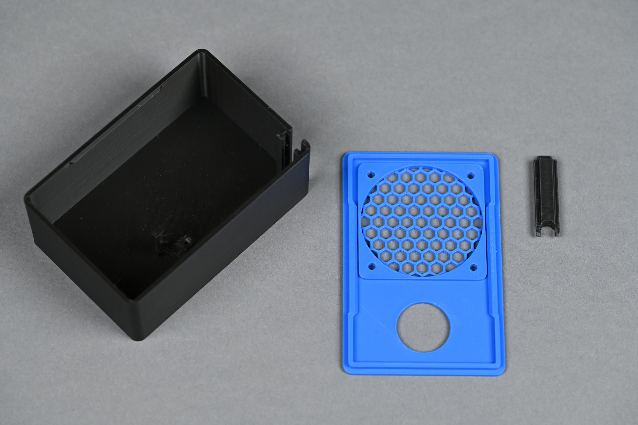
The pieces of the 3D printed enclosure include the box, a snap-fit lid, and a piece that slides into a notch in the back of the enclosure to accommodate a permanently attached USB cable.
The enclosure presented three design challenges: mounting the speaker, allowing the USB cable to escape the enclosure, and holding the electronics in place.
Mounting the Speaker
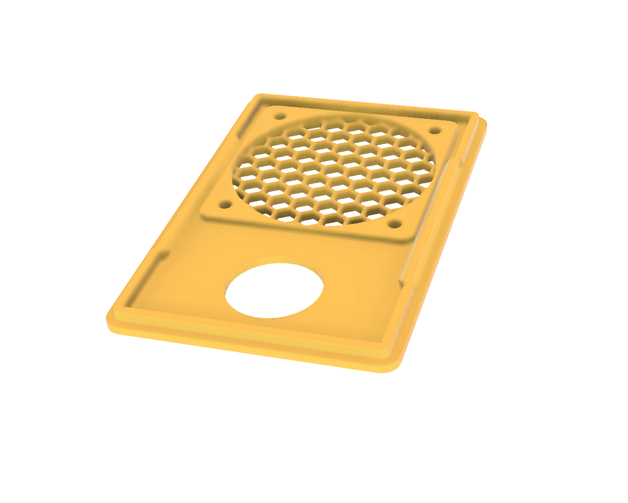
The lid with a 51 mm x 1.5 mm deep circular cutout for the lip around the speaker’s rubber surround.
The speaker has a lip around the rubber surround. It’s about 50 mm in diameter and 1 mm tall. To accommodate the lip, I added a 1.5 mm raised square area with a 51 circular cutout for the speaker and its lip to the underside of the lid. This makes the lid 3.5 mm thick in this area, 2 mm thick where the grill is, and 2 mm thick elsewhere. The four holes in the corner are 42 mm apart and 3.3 mm in diameter for a loose fit with M3 screws.
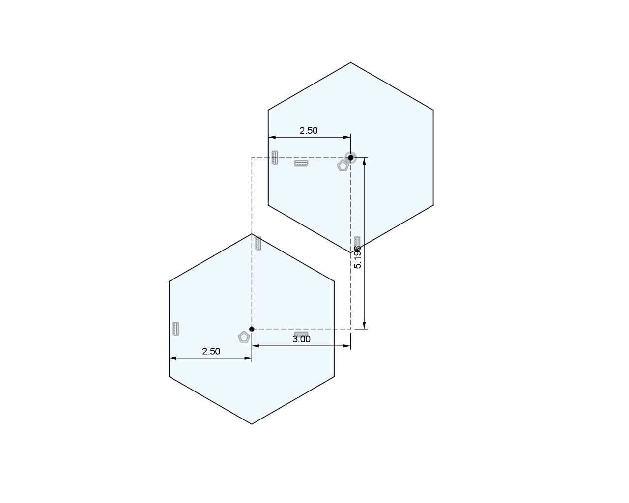
The centers of the two hexagons are located on the hypotenuse of a 30-60-90 triangle with a length of 6 mm.
The hexagon grill was created by drawing two hexagons then using the rectangular pattern tool to repeat the two hexagons in both the vertical and horizontal directions. The hexagons are 5 mm across with 1 mm between their sides. This is a spacing of 6 mm on center.
The first hexagon was located in the center of the grill. The center of the second hexagon needed to be 6 mm from the center of the first hexagon but on a diagonal. This diagonal is the hypotenuse of a 30-60-90 triangle. If the hypotenuse is 6 mm, the short side of the triangle is 6/2 = 3 mm and the long side of the triangle is 6/2*sqrt(3) = 5.196 mm.
I used the construction line type to draw a 3 mm x 5.196 mm two point rectangle from the center of the first hexagon down and to the left then placed the center of the second hexagon on the second corner of the rectangle as shown in the image above.
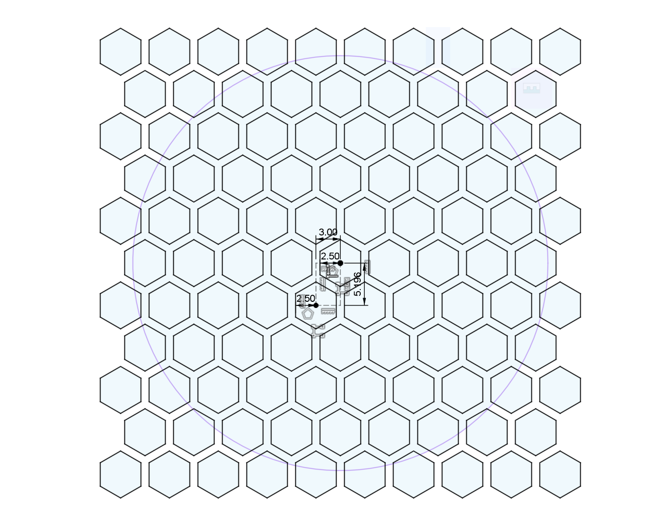
The hexagon sketch used to create the speaker grill.
After the two hexagons were in place, I used the rectangular pattern tool to duplicate the two hexagons across the entire speaker grill. The x spacing was 6 mm and the y spacing was 6*sqrt(3) = 10.392 mm. These are just double the values used to sketch the rectangle used to space the first two hexagons. I was then able to use the extrusion tool to cut the hexagons through the 51 mm diameter circular grill area on the lid.
The USB Cable Slot
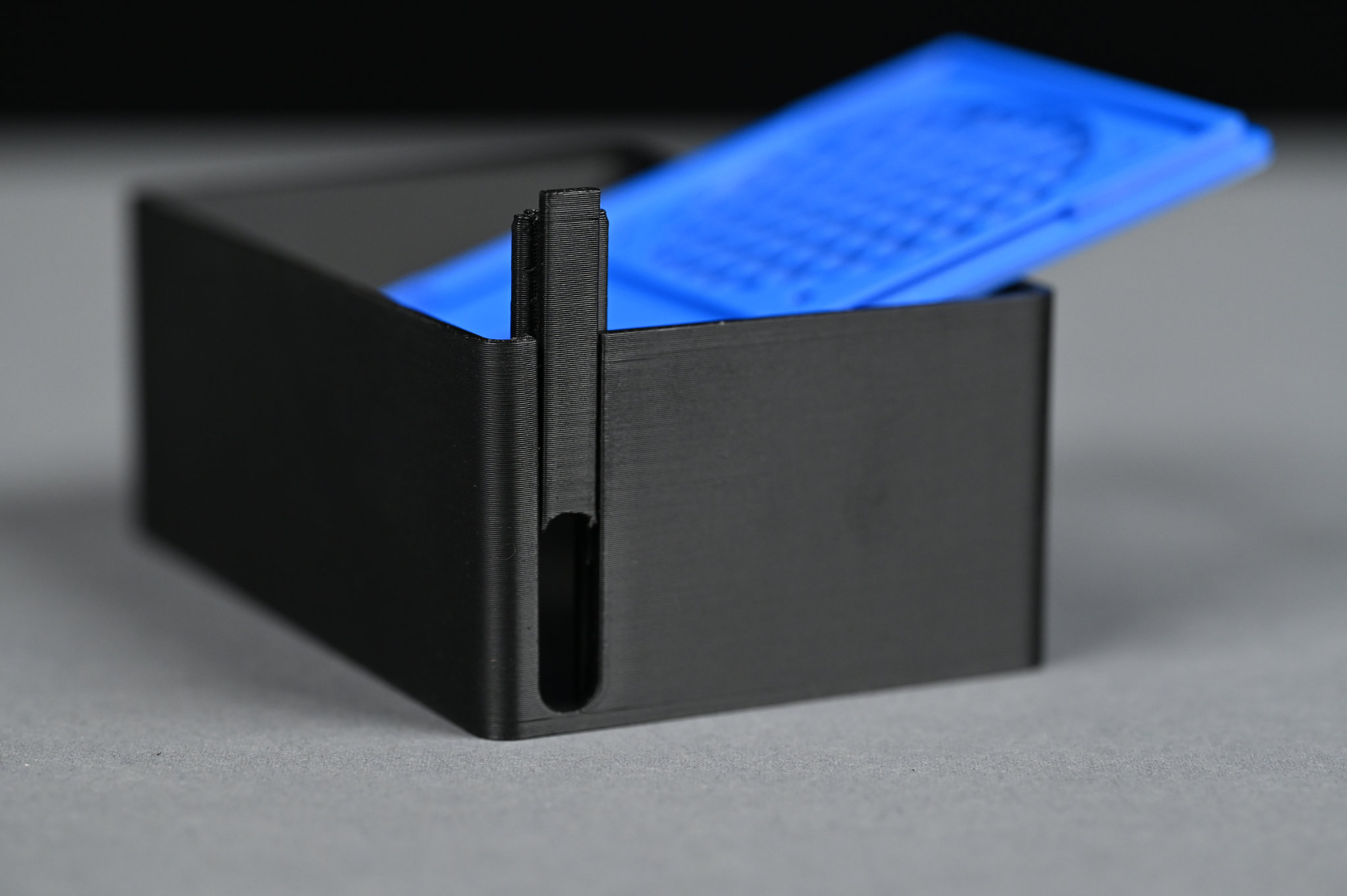
This piece slides into the notch of the enclosure to hold the USB cable in place.
When I first built this enclosure, I did not have the panel mount USB C extension cable and clearly a USB C connector is not going to pass through a hole just large enough for the actual USB cable.
To run the USB cable out of the enclosure, I created a small slot in the enclosure. I slipped the cable through this slot. Once the cable was through, I printed a filler piece that slipped into the slot and held the cable in place.
Room for the Electronics
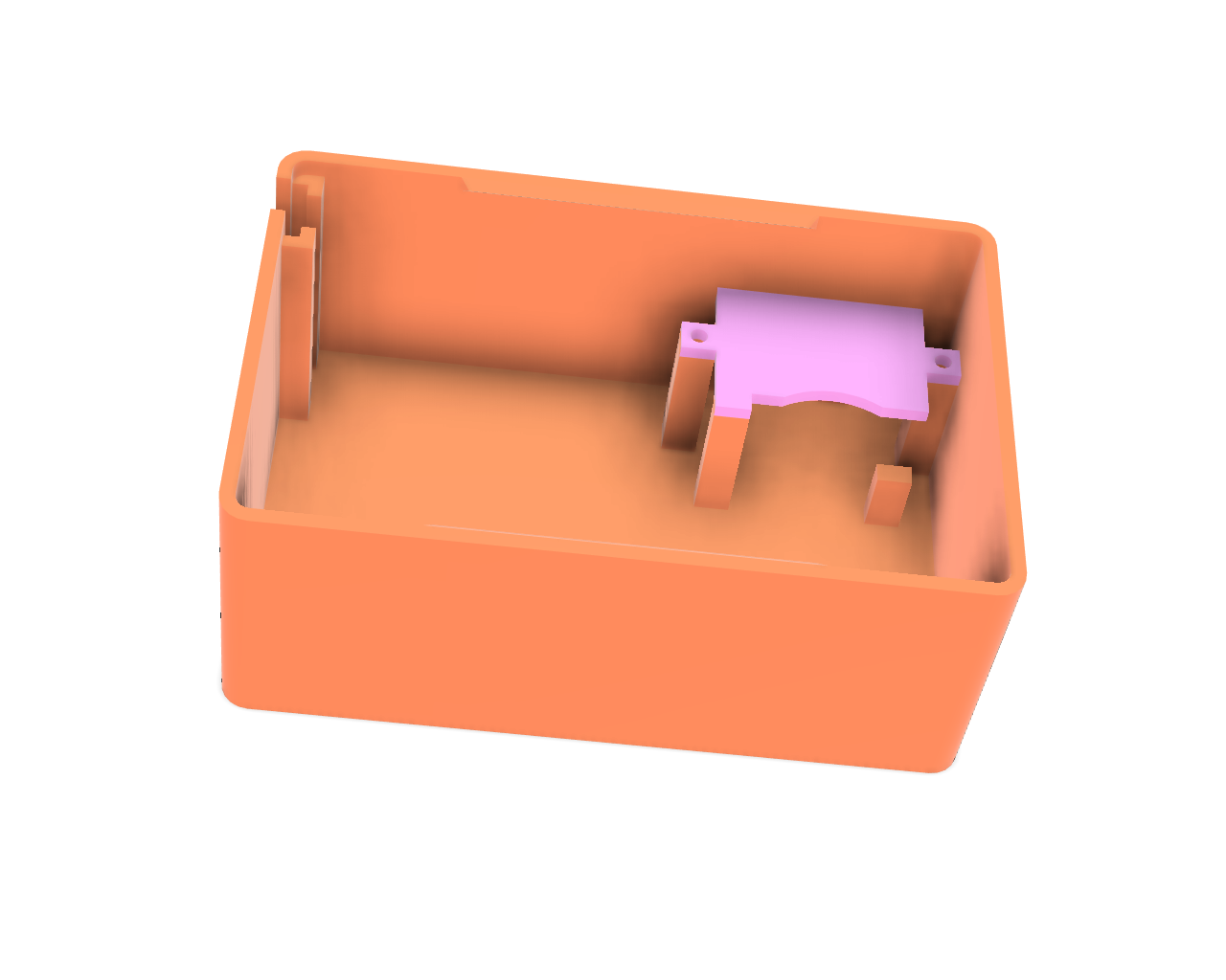
Some posts and a small cover keep the electronics in place and from shorting to the speaker or button.
To hold the electronics in place, I added a few posts to the bottom left of the enclosure and printed a little cover for them. The electronics slip in sideways with the USB cable up top and running to the left in the picture above. The cover is held in place using a pair of M2.5 screws. This keeps the electronics from moving around and shorting to the speaker or button.
The Result
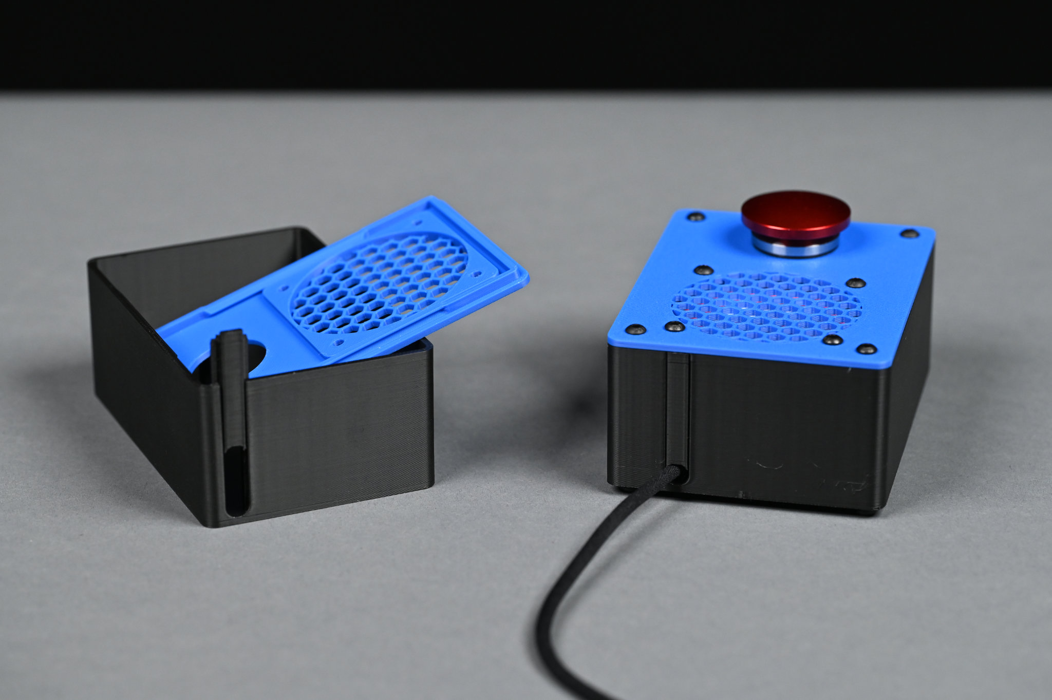
USB cable installed. Version 1 of the enclosure on the left. Version 2 of the enclosure on the right.
This version of the case worked out great except for one fatal flaw: the snap together lid fit somewhat loose into the case. This caused the lid to rattle every time the sounds played back! Instead of getting nice clean audio, I’d get audio plus a lot of rattling noises. I decided the next version would use screws to hold everything together tightly to stop the rattling.
Version 2
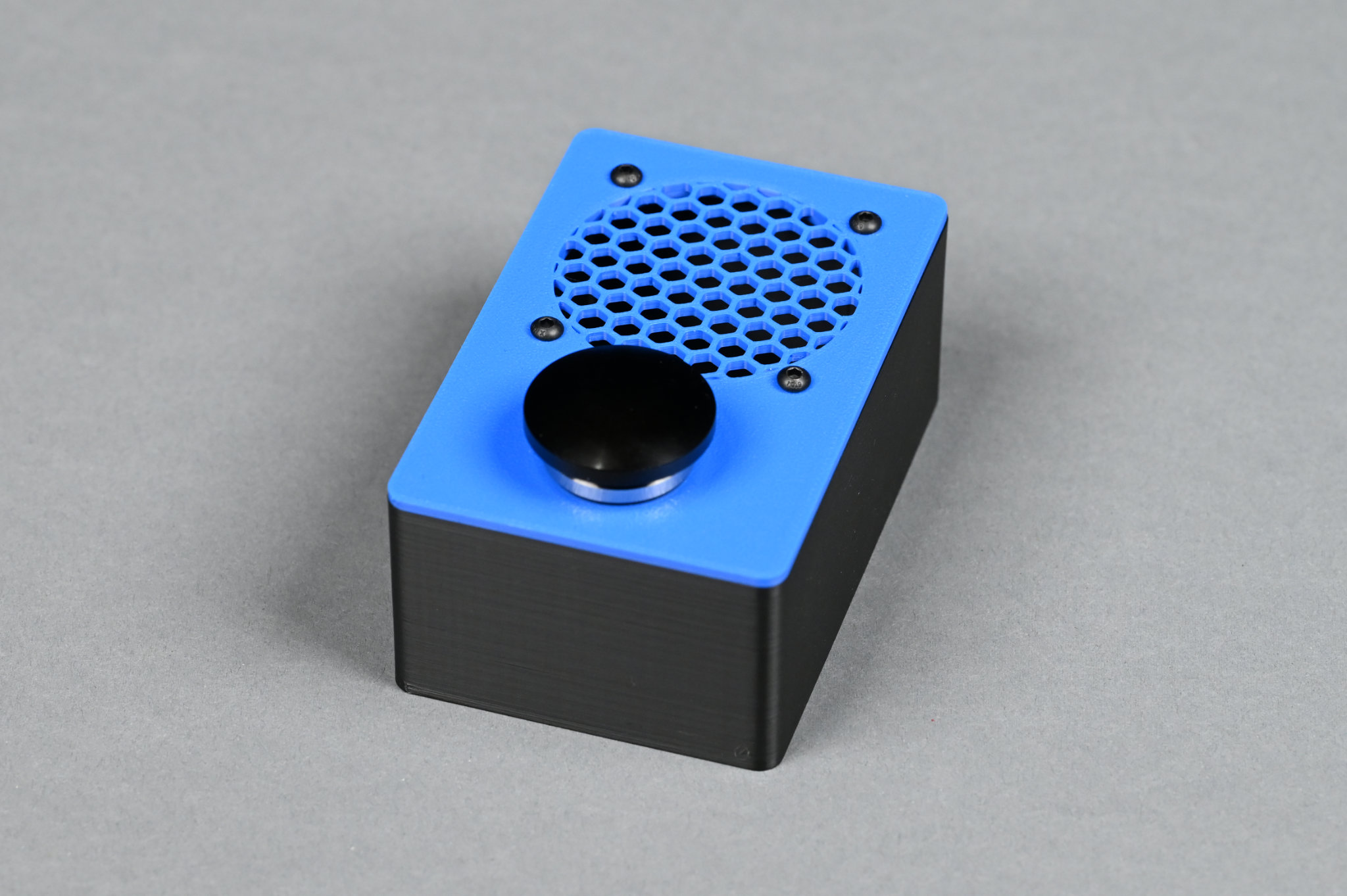
The second version of the project. It’s a bit wider and the cover screws to the base now.
Version 2 of the enclosure is more or less identical to version 1 of the enclosure except there are now four M3 screws in the corners to hold the case together. The case grew from 66 mm wide to 75 mm wide to accommodate the screws. This version of the case is 100 x 75 x 42 mm.
The 3 mm holes in the corners fit M3 screws.
The holes in the lid are 3.3 mm in diameter for a loose fit with M3 screws. The holes in the base are 3 mm diameter so that the M3 screws will bite and thread into them—just don’t over tighten them. The walls of the screws holes are 1.5 mm at their thinnest.
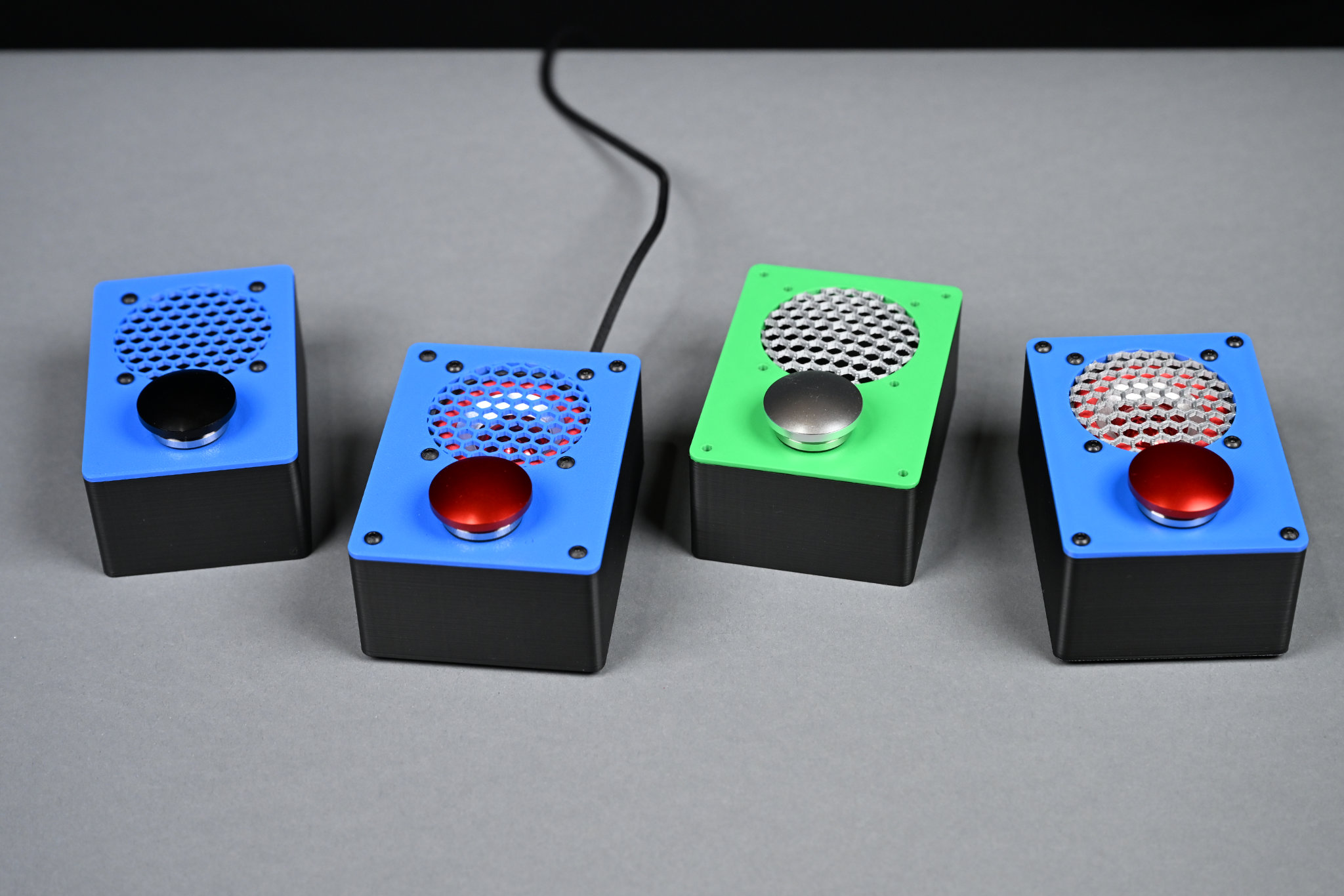
The Result
This version worked well and the case no longer rattled. With the basics out of the way, it was time to get creative and try out multi-color prints and different print support materials.
Version 3
The third version of the enclosure. This version is 4 mm narrower than version 3 and sports a raised silver speaker grill.
For the third version of the enclosure, I realized I could make it 4 mm narrower and still have room for the screws in the corners. I also wanted to try to make a domed silver speaker grill like you might see on an old outdoor intercom panel or on industrial equipment. This version of the enclosure measures 100 x 71 x 42 mm.
Designing the Grill
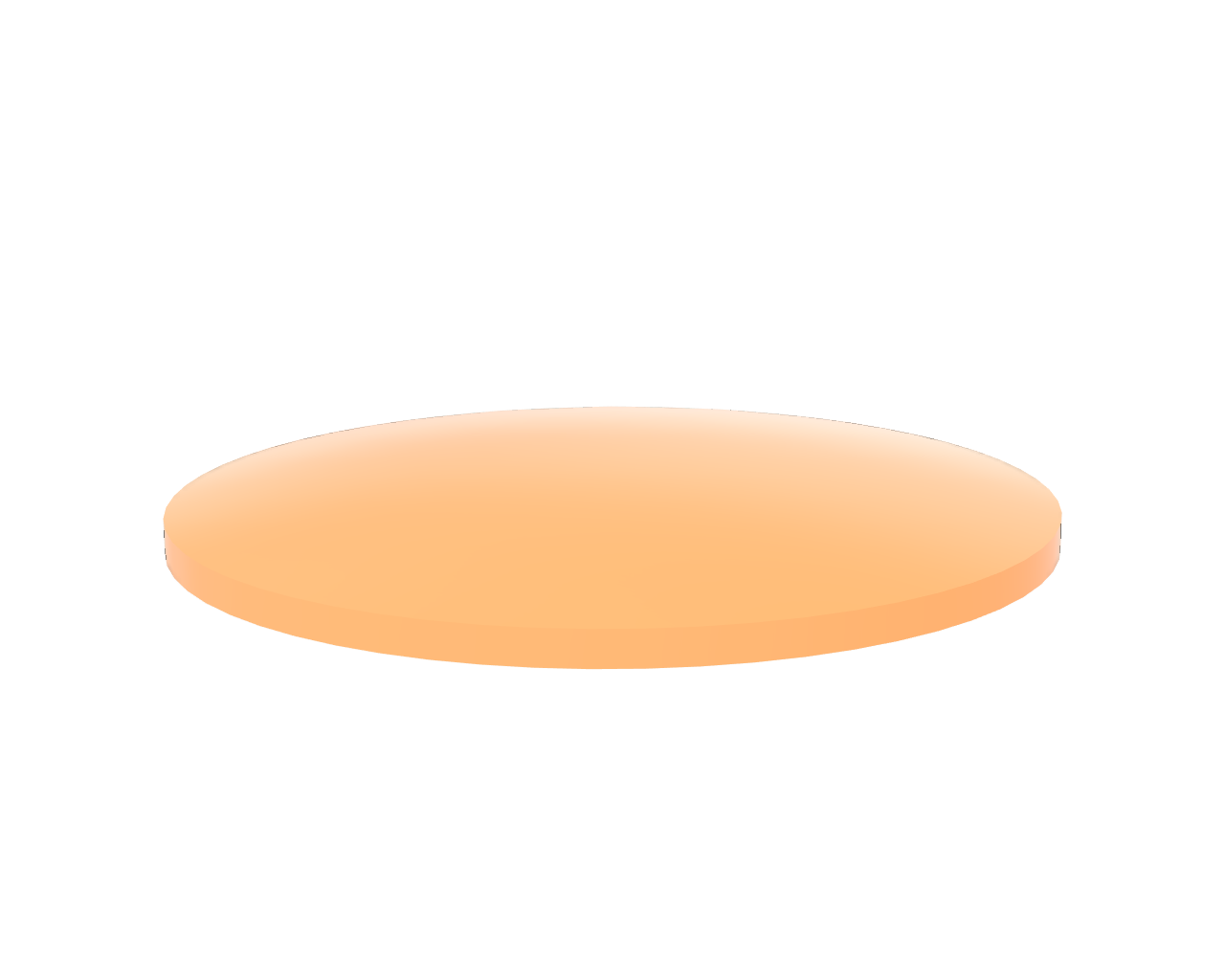
51 mm diameter speaker grill before embossing. The radius of the top surface is 110 mm and the bottom surface is flat. It’s 2 mm thick at the outside edge.
The grill started as a 51 mm disc with a flat bottom and gently curved top surface. It’s 2 mm thick at the edges and a few millimeters thicker in the middle. It started as a sketch of the right half of the disc’s cross section then I used the revolve tool to spin the cross section into the solid disc.
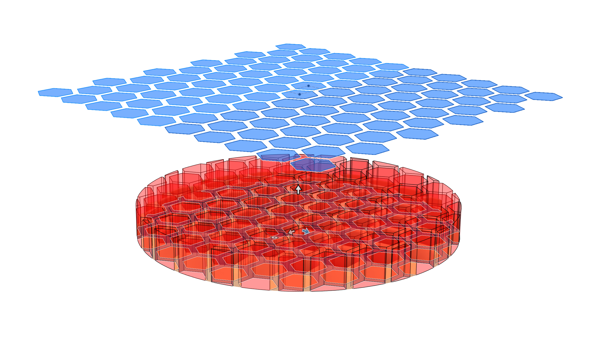
The Fusion emboss tool in action. The plane with the hexagons is offset 20 mm from the outside top edge of the disc. The emboss tool worked best with only a single curved surface so the top surface is curved and the bottom surface is flat.
I stuck with the same hexagon pattern as for the flat speaker grill. I positioned it 20 mm above the disc then used the emboss tool to cut the hexagons into the disc. The emboss tool cuts the hexagons with their sides angled inward toward the center of the sphere forming the top surface of the disc. The emboss tool results in a grill that looks like it was formed from pressing a metal screen between two spherical dies while the extrude tool would have resulted in a grill that looks like it was punched into a sheet of metal.
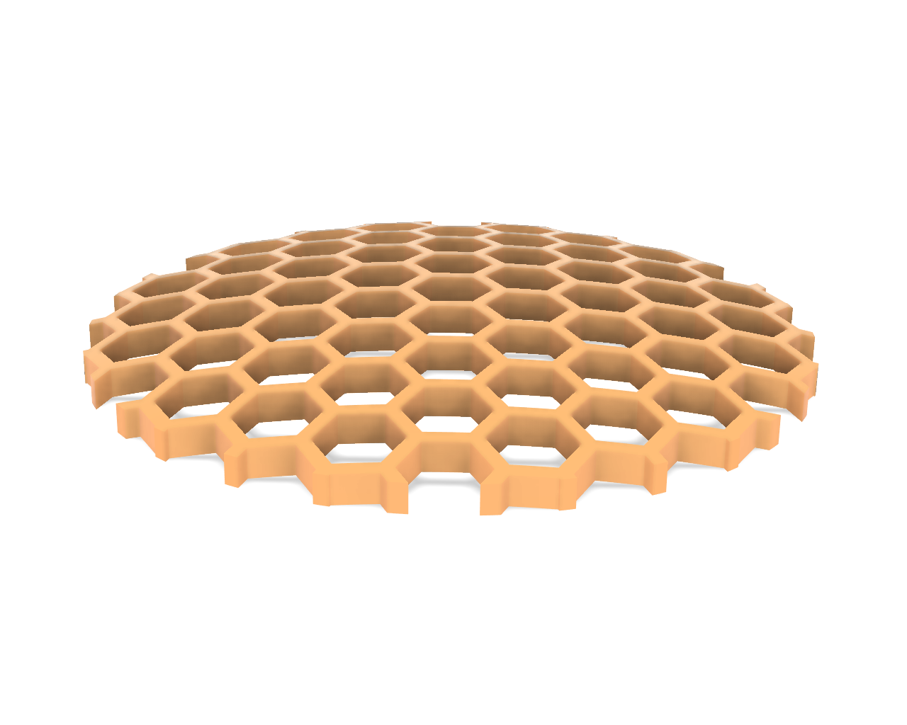
The finished grill as a separate component. It’s 51 mm in diameter and 2 mm thick throughout. The flat bottom surface has had some curvature cut into it.
The last step was to scoop out the bottom of the disc to make it a near-uniform 2 mm thick across its entire surface. I added the bottom curve to the disc’s cross section sketch then used the revolve tool a second time to cut the bottom curve out. The final result is shown above. This was created as a separate component in a separate file so I could paste it where needed.
Printing the Grill
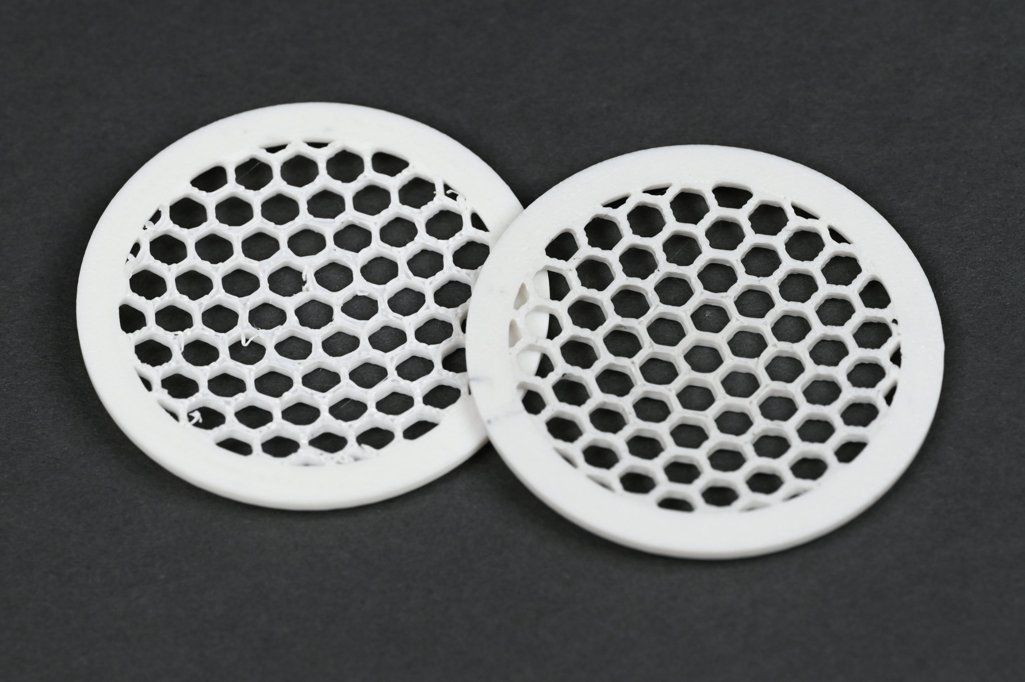
Two attempts at prototyping the speaker grill. The one on the right printed with a PETG support interface cleaned up nicer than the 100% PLA print on the left.
I made two test prints of the grill. The first test print was out of white PLA using white PLA for the support material. This print is on the left in the photo above. It turned out well except there were lots of strands of PLA leftover where the support could not be cleanly separated from the design.
The second test print was out of white PLA with white PLA support but with black PETG for the support interface. The support and the design separated very easily from each other leaving very little residual support material behind. The print’s purge settings probably needed to be adjusted a bit because the white PLA was a tad darker from the PETG mixing into it.
Exporting Multicolored Prints from Fusion to the Bambu Slicer
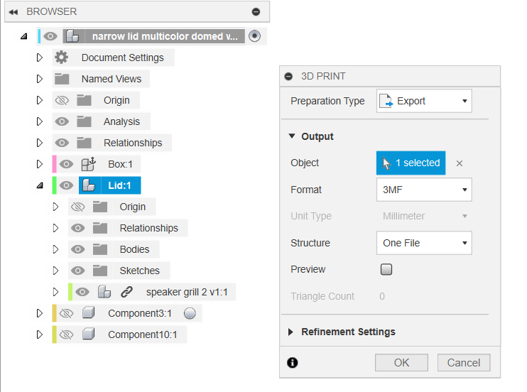
Example of exporting a component consisting of multiple bodies from Fusion for multicolored printing in the Bambu slicer.
Next up was to figure out how to print the main part of the lid in one color and the speaker grill in a second color. The trick to exporting prints from Fusion to the Bambu slicer for multicolored printing is to export a single component containing separate sub-components or bodies for each different color in the print.
In the case of the lid, I have a body and a sub-component inside the main lid component. The body is most of the lid. The sub-component is just the speaker grill and the grill is held in place in the lid with a rigid joint.
Inside Fusion, I select 3D print then click in the design browser on the main component containing the bodies and/or subcomponents. This gets exported as a single .3mf file (above) that can be imported into the Bambu slicer (below).
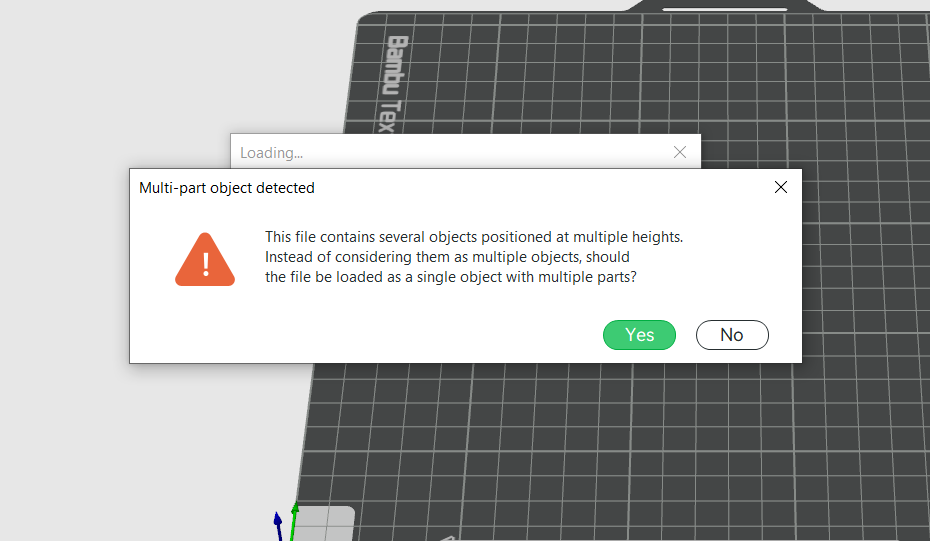
Answer yes to this question.
When the file is imported into the slicer, the slicer will show the dialog box in the screen capture above. Click yes. The Bambu slicer will now treat the imported design as a single design consisting of multiple objects.
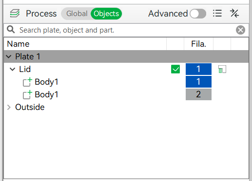
Click the Objects button next to the Process label to display a list of objects in the design and assign a filament slot to each.
Clicking the Process from Global to Objects will display a list of objects in the design. You can now click on an object in the objects list then type a number key corresponding to a project’s filament slot and that object will be printed out of the filament assigned to that slot in the project.
The Result
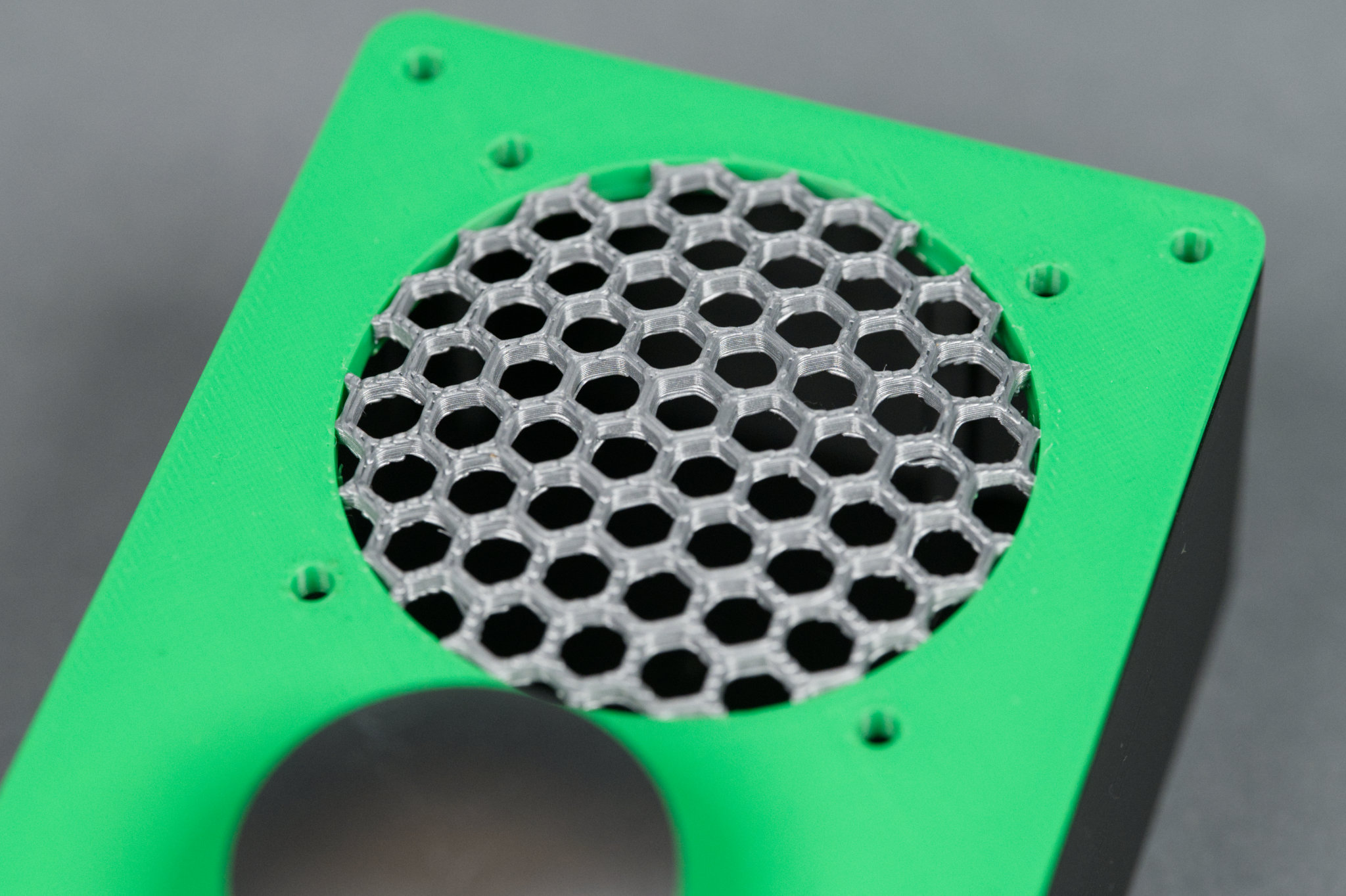
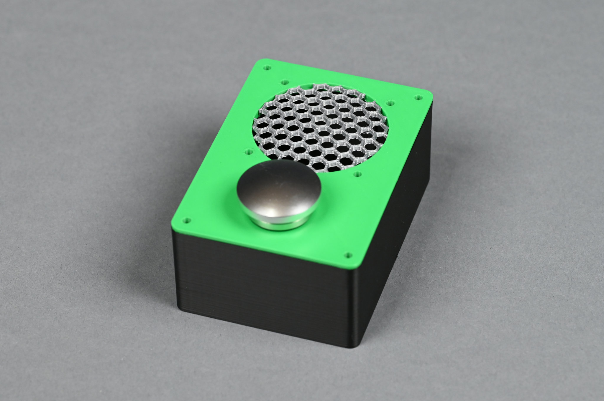
A close up of the raised silver hexagon speaker grill on the third version of the enclosure.
Convinced I had the grill and support and multicolored printing figured out, I printed out version 3 of the enclosure. This is the first version of the enclosure to be printed with the lid right side up. The first two versions where printed with the lid facing down to eliminate the need for support material. Obviously with a domed speaker grill, support material would be needed regardless of which direction the lid faced.
This time I used green for the enclosure—it’s what was in the printer—and silver for the grill. I just printed everything in PLA without worrying about the support interface. The final print is shown in the image above. It turned out pretty well even using PLA for the support material! Peeling away the support material from the bottom of the lid was a bit of a pain though.
Final Version
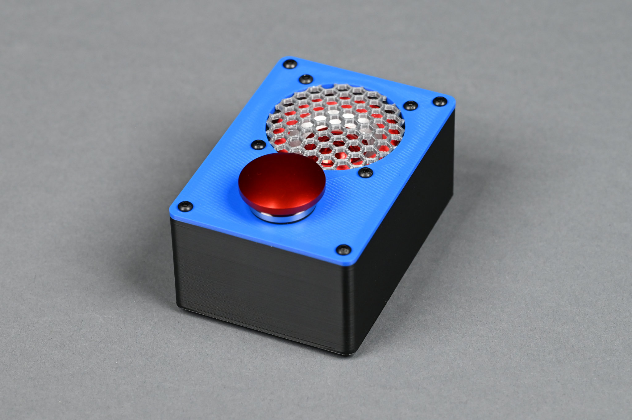
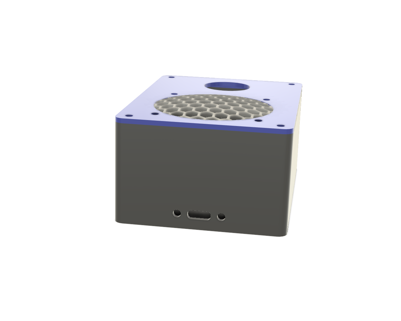
The final version of the enclosure. This one is 2 mm taller but loses the USB C pigtail in favor of a rear-mounted USB C connector.
After assembling version 3 of the enclosure, I started searching for some USB C panel mount connectors so I could eliminate the dangling USB cable from the project. I found one but it required increasing the height of the enclosure by 2 mm to fit underneath the speaker. This version of the enclosure increased to 100 x 71 x 44 mm in size.
Adding a USB C Connector
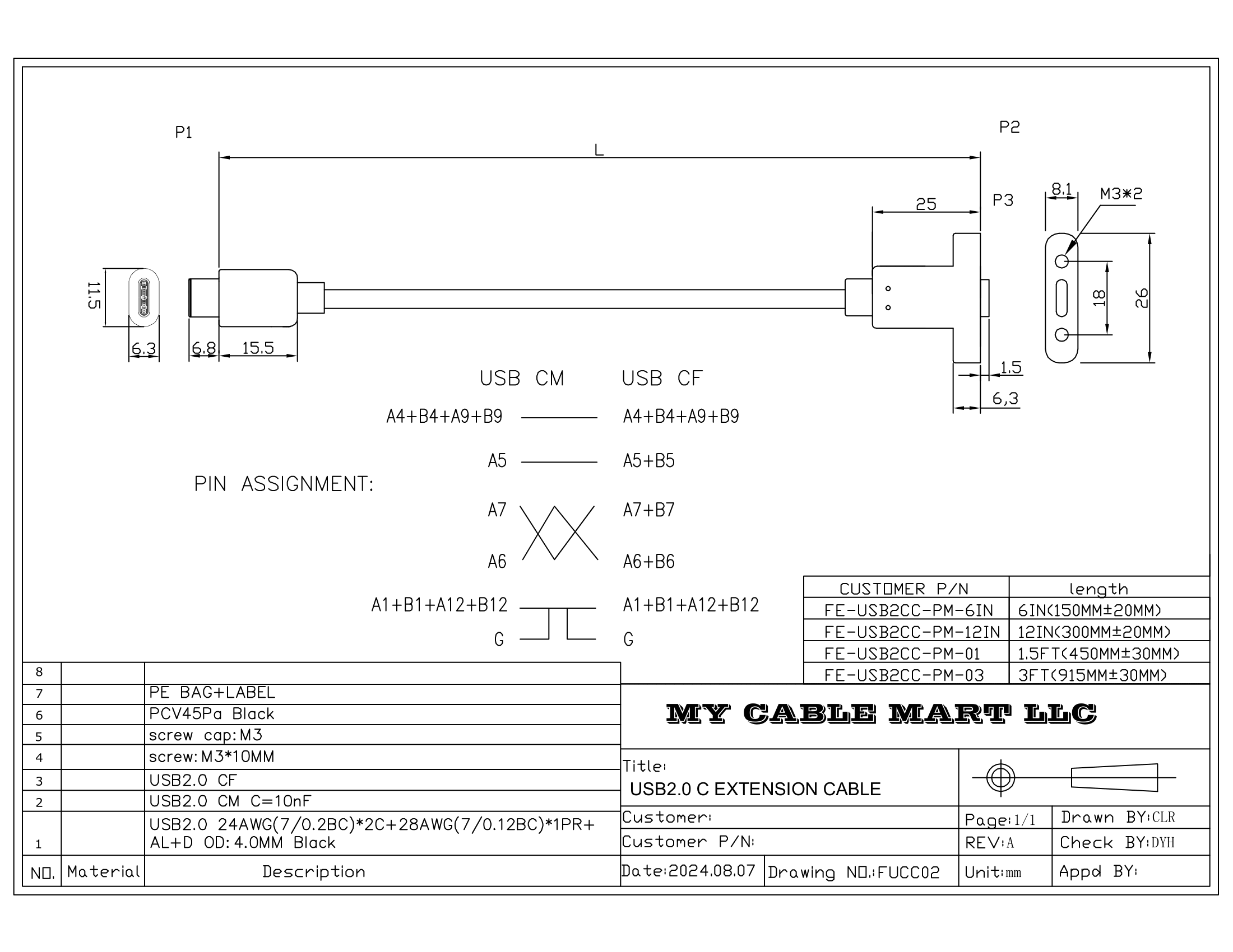
The datasheet with the dimensions of the panel-mount USB C extension.
After much digging around, I found a panel-mount USB 2.0 Type C extension cable. The retailer even had a dimensioned drawing (shown above).
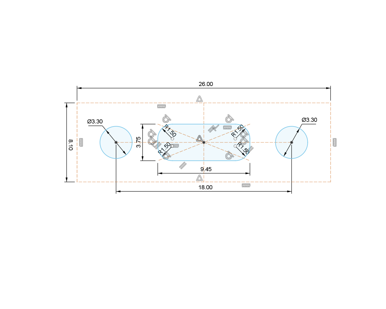
USB Type C panel cutout dimensions.
I used the drawing and some other resources to put together a panel cutout for the rear of the enclosure. I then placed the cutout on the rear of the enclosure and used the sketch to cut holes in the enclosure.
The rear of the case with the cutout for the panel-mount USB C connector.
Printing the Lid
This time I printed the lid in Bambu’s cobalt blue and silver basic PLA using their new support for PLA material for the support interface. Using this material for the support interface made it easy to separate the support and design from each other.
The Result
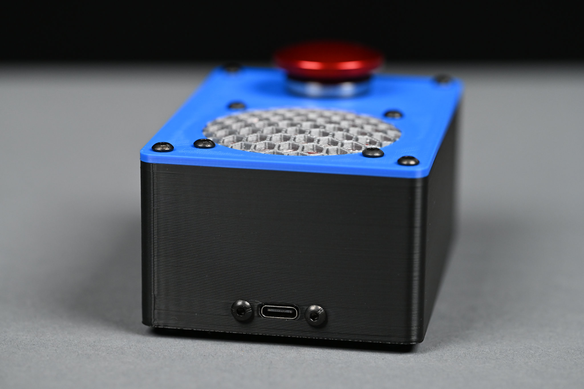
The rear of the final version of the enclosure with the panel-mount USB C connector installed.
The photo above shows the finished and final version of the enclosure. Both the USB connector and domed silver speaker grill came out well!
Printing the Enclosure
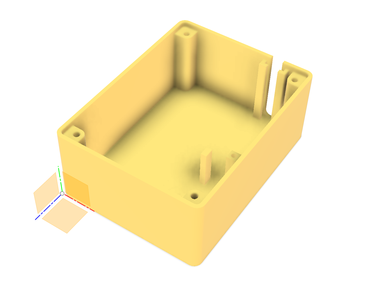
The Base
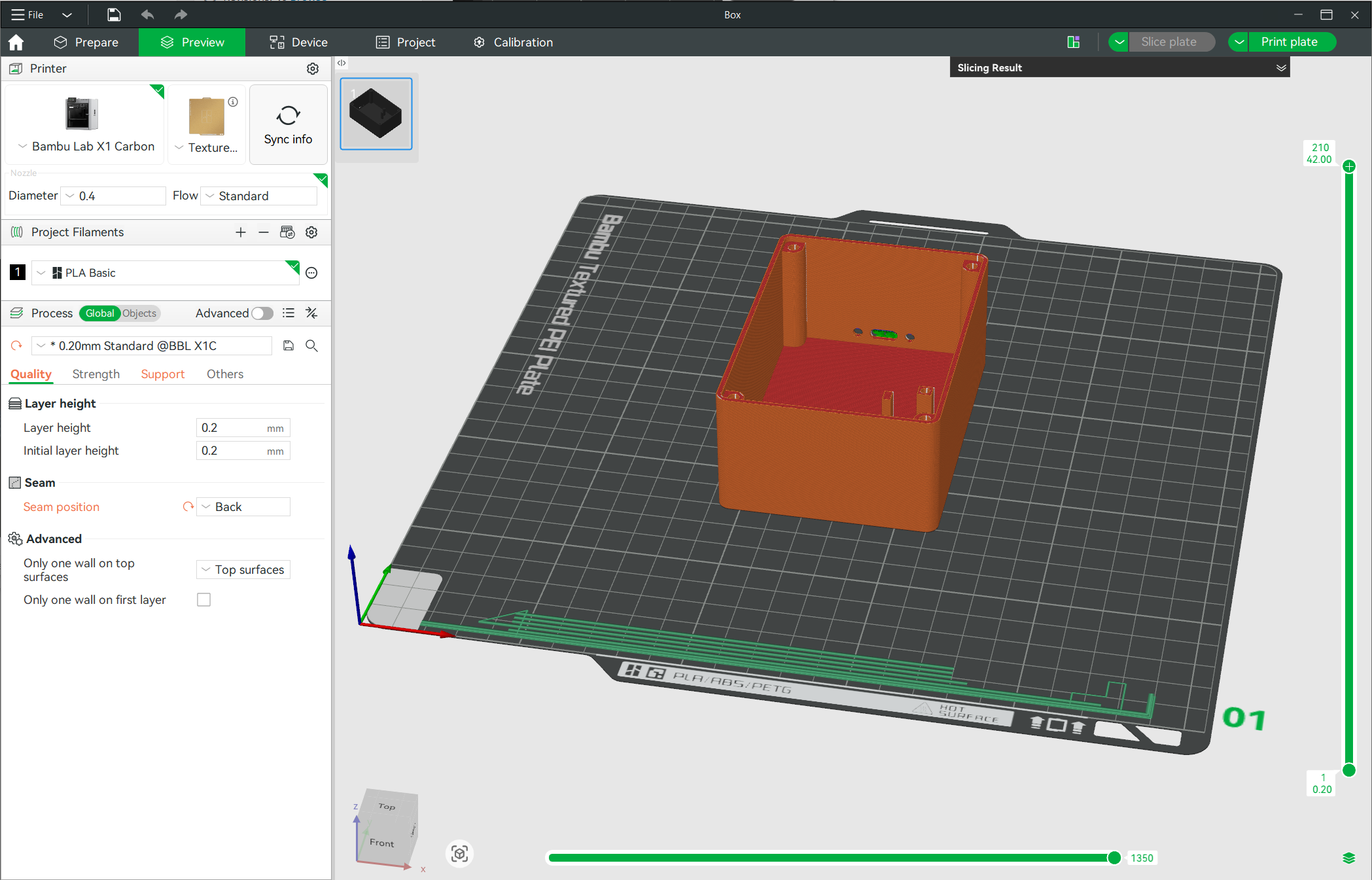
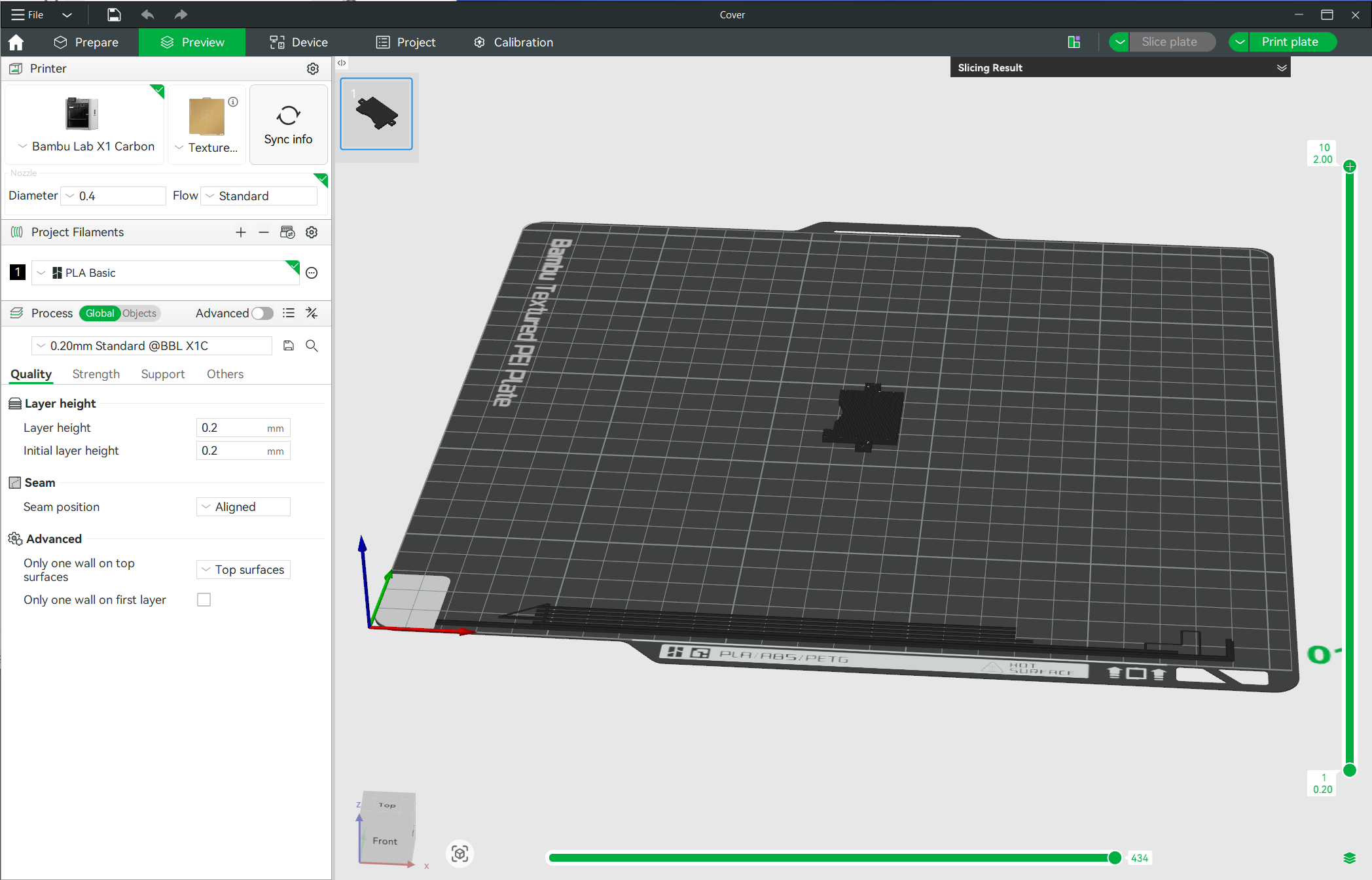
The Bambu slicer open with the base of the enclosure loaded and ready to print.
I printed the base on my Bambu X1C using the “0.20 standard” slicer settings. I set the seam alignment to back and enabled supports on the oval cutout for the USB connector. This is a pretty basic print. Total print time was 1 hour and 11 minutes with no filament changes.
The Lid
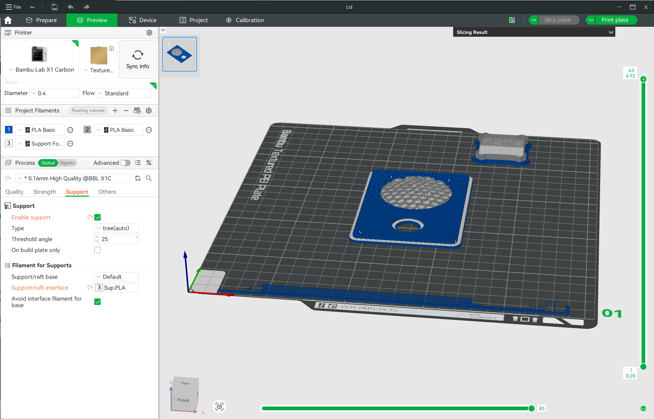
The Bambu slicer open with the enclosure lid loaded and ready to print.
The lid is a significantly more complicated print than the base. I started with the “0.16 high quality” settings then enabled support generation. I used Bambu’s cobalt blue and silver basic PLA for the lid and speaker grill respectively. For the support interface, I used Bambu’s new support for PLA material.
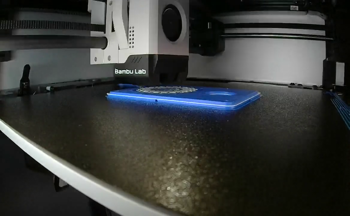
Screen capture from the time lapse video of the Bambu X1C 3D printer printing the enclosure lid.
This print took 3 hours and 26 minutes with 46 filament changes! The photo above shows the printer putting down a support interface layer of the Bambu support for PLA material.
The Electronics Cover
The cover for the electronics.
The final print is the cover for the electronics. This one is pretty trivial and it really doesn’t matter what material or color it is printed out of. I used black PLA. Total print time was ten and a half minutes. It’s even upside down in the screenshot above though it doesn’t matter.
Assembly
With all the materials gathered together and all the parts printed out, it’s time to assemble the project! (The design files and the complete bill of materials to use as a handy checklist as you procure the required parts and materials are available at the end of this post.)
1) Connect the button to the qwiic cable
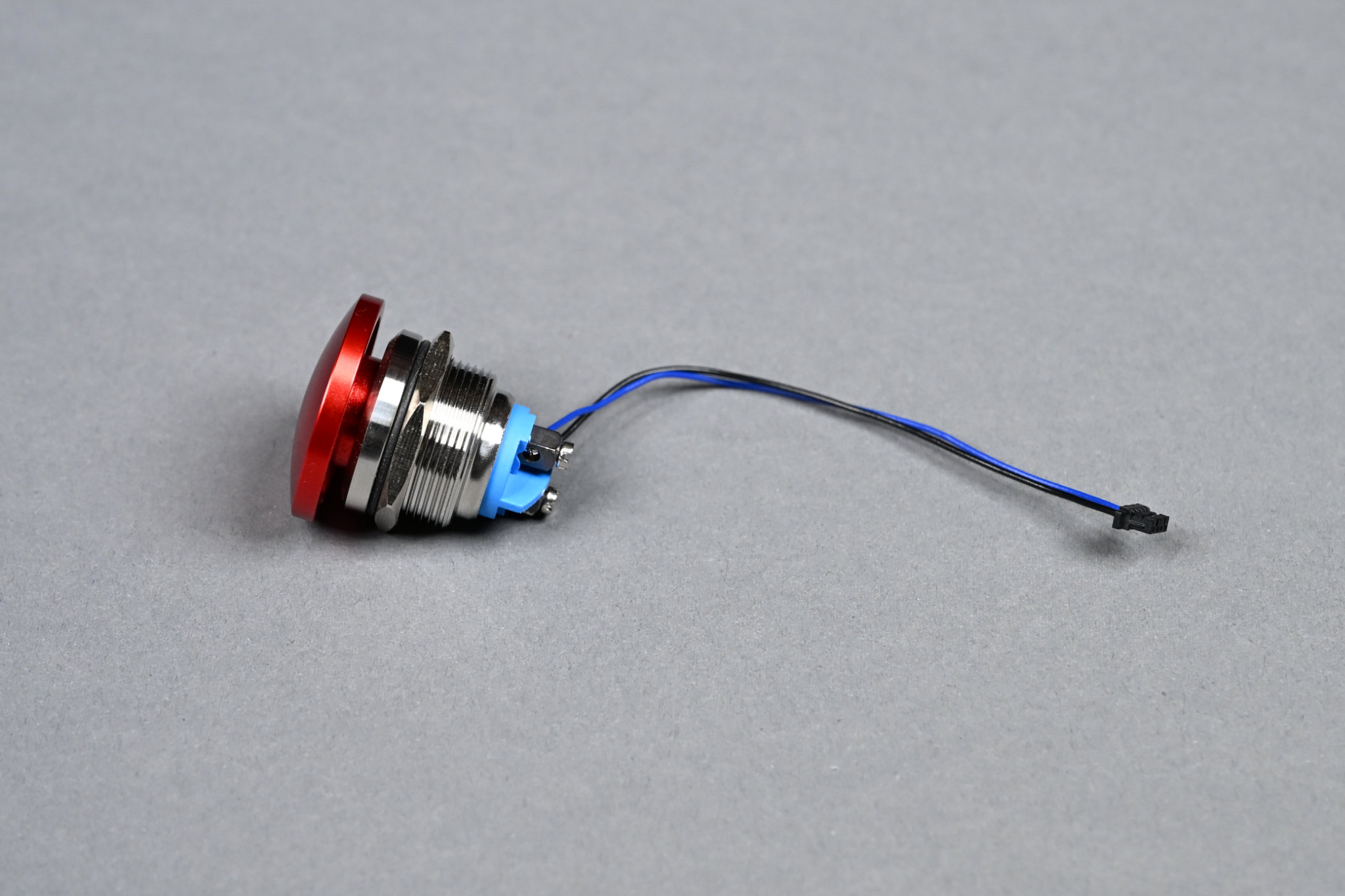
I used a sewing needle to remove the unneeded red and yellow wires from the JST connector.
Connect the button to the black (GND) and blue (SDA) wires on the qwiic cable. I removed the red and yellow wire from the JST connector using a sewing needle and gently prying up on the plastic tabs then backing the unneeded wires out of the connector.
2) Solder the picoblade cable to the speaker
Polarity doesn’t matter on the speaker connections.
Solder the wires on the picoblade cable to the speaker terminals. Polarity doesn’t matter since this is mono so phasing doesn’t matter and we don’t care if a positive voltage makes a positive or negative displacement of the diaphragm.
3) Solder the header pins on the QT Py
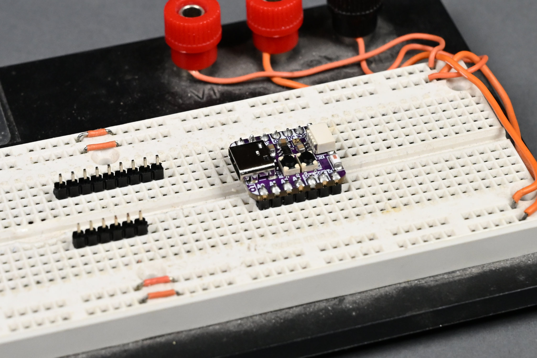
If you have an old breadboard, soldering the headers becomes vastly easier.
Solder the header pins on to the QT Py board. You can use an old breadboard to hold the pins straight and upright while you solder if you have one. This is the Qt PY ESP32-S3 board but it’s the same pinout and process if you’re using the Qt PY RP2040 board.
4) Solder the header sockets on the Audio BFF
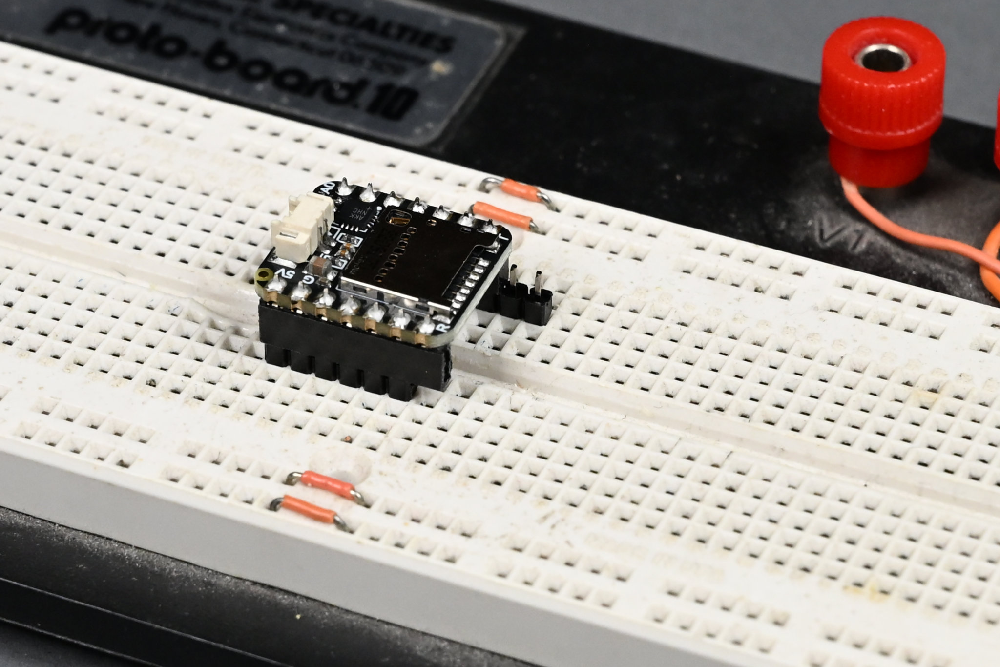
Stick some unused header pins into the breadboard then set the header sockets on the pins for easier soldering.
Solder the header sockets on to the Audio BFF board. You can use a breadboard and some spare header pins to hold everything in place while soldering.
5) Connect the electronics together
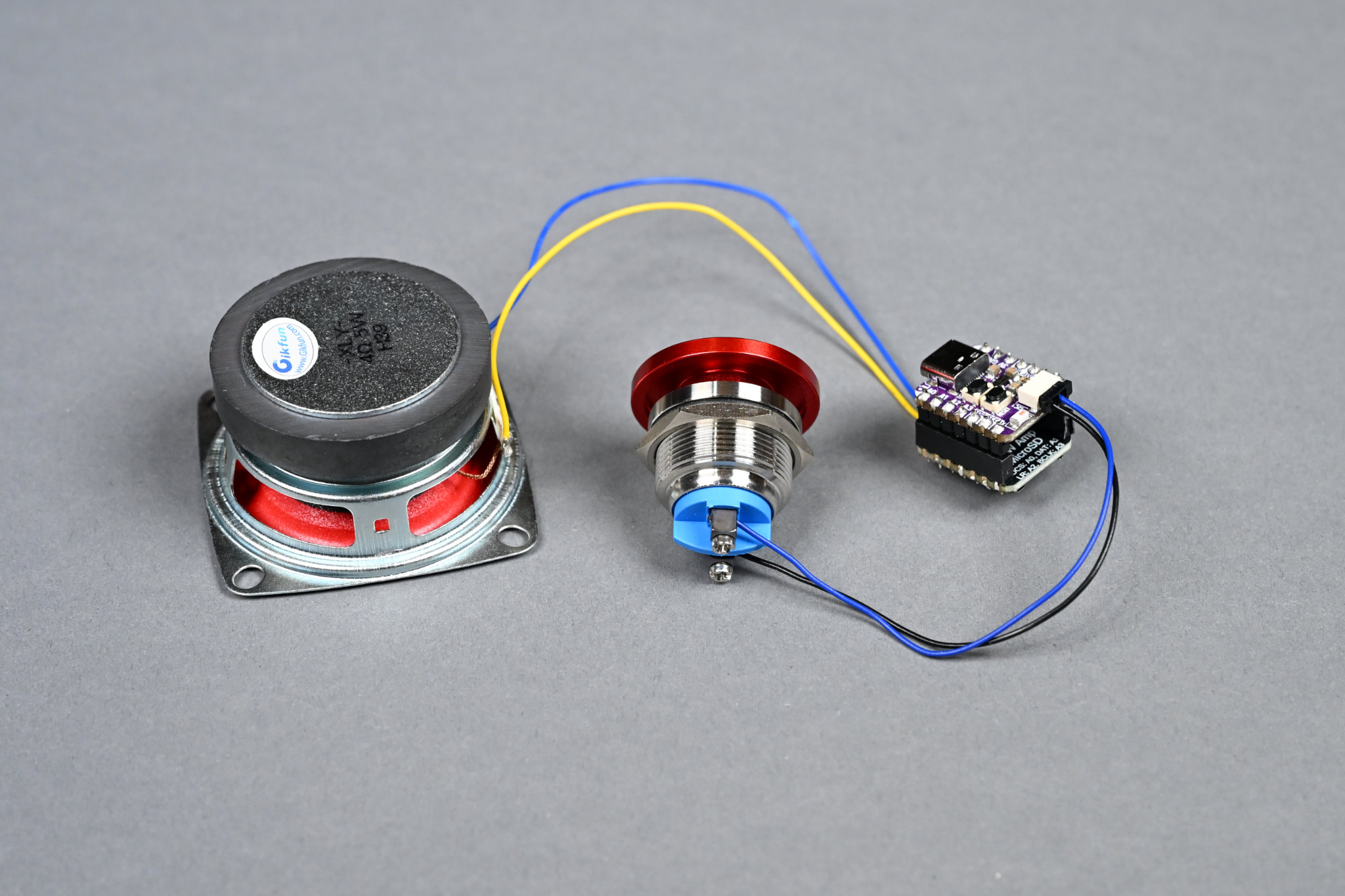
When connected correctly, the speaker and button cables will be on opposite ends of the stack of boards.
Plug the boards into each other and connect the button and speaker to the boards. Pay close attention that the two boards are aligned so that the power and data pins are aligned and they are not rotated 180° or shifted by a pin.
6) Install the microSD card
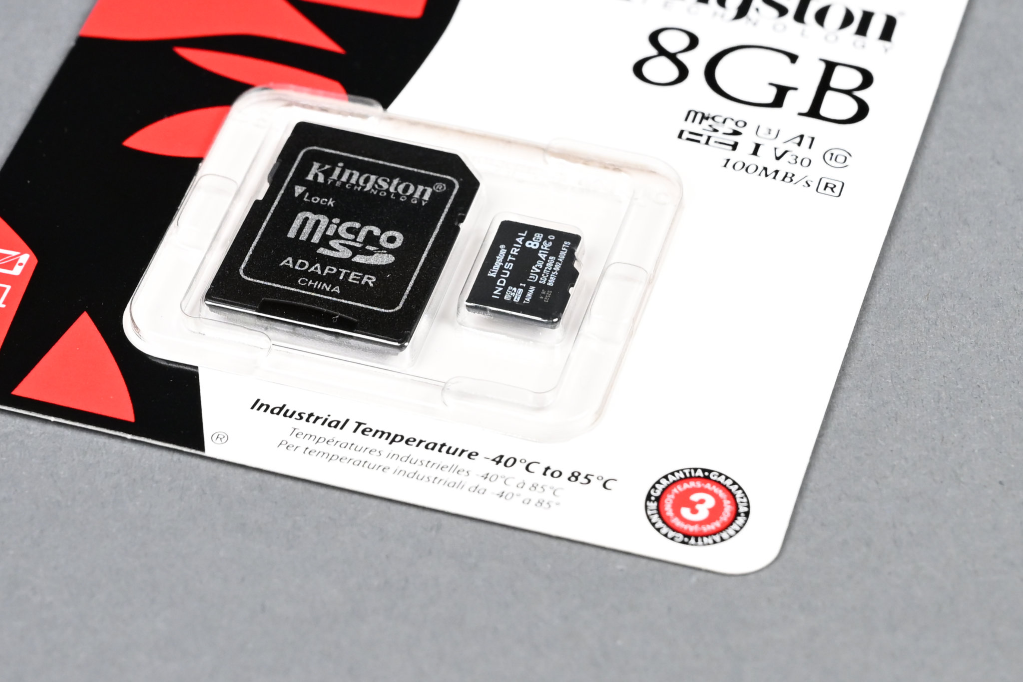
The smallest reputable microSD card I could find and easily acquire in 2025.
Format and copy a mono 22,050 Hz, 16-bit, little-endian wave file to the microSD card and install the microSD card in the audio BFF board’s microSD slot. Free software such as Audacity or FFMPEG can be used to convert the files if you only have an MP3. If you’re using the I2S Amplifier BFF board, you’ll copy the sound file to the QT Py’s on-board flash as part of installing the software later.
7) Test everything
Hopefully the speaker made some sort of noise.
At this point, it’s a good idea to test everything. Follow the instructions under the software heading below to install CircuitPython and the soundboard software. Have some fun. Once everything is tested, unplug the speaker and pushbutton from the electronics and continue assembly.
8) Mount the pushbutton to the lid
The pushbutton mounted to the lid.
Thread the button through the lid and nut then tighten the nut on the back of the button. Finger tight is good enough.
9) Mount the speaker to the lid
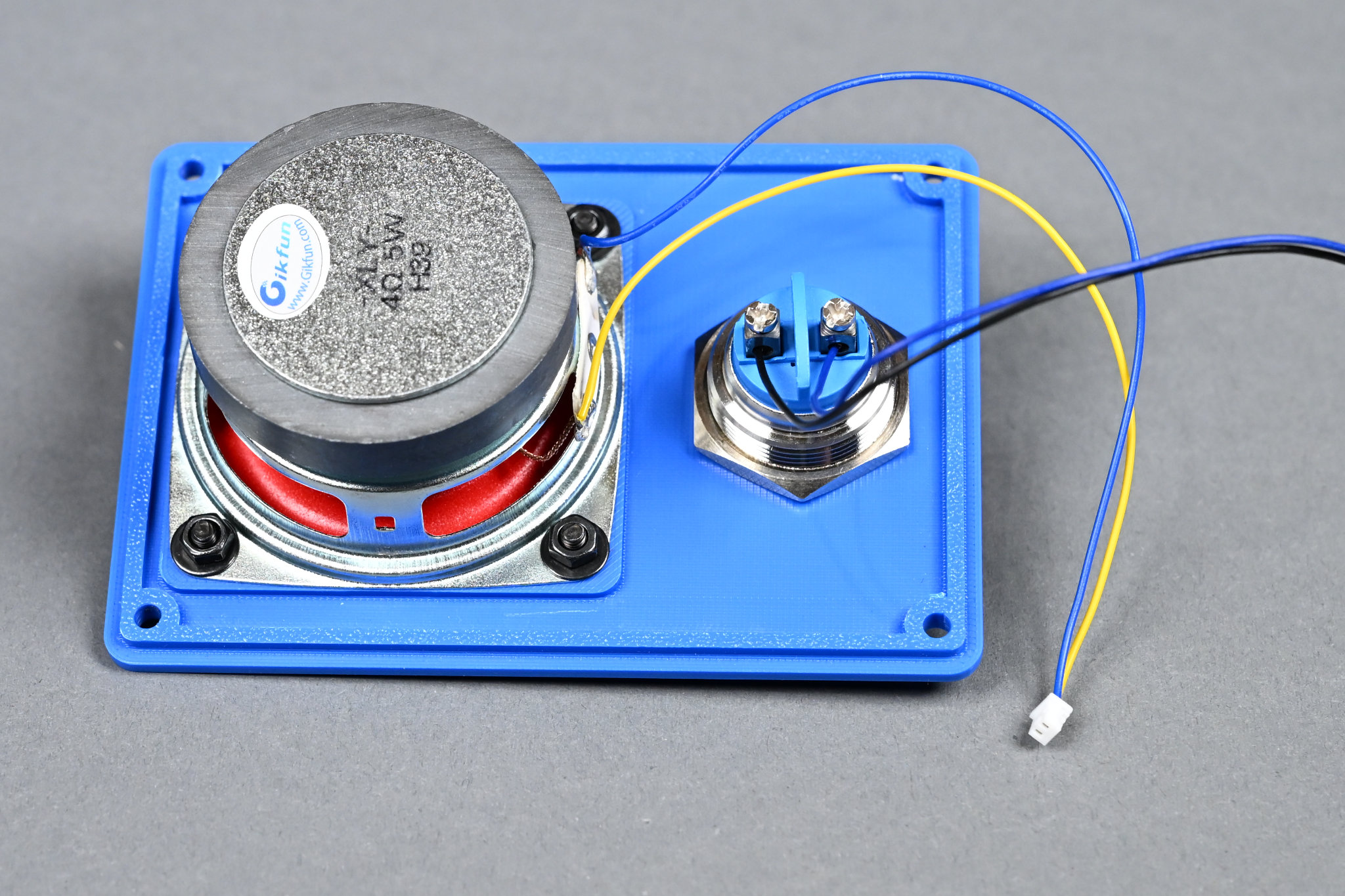
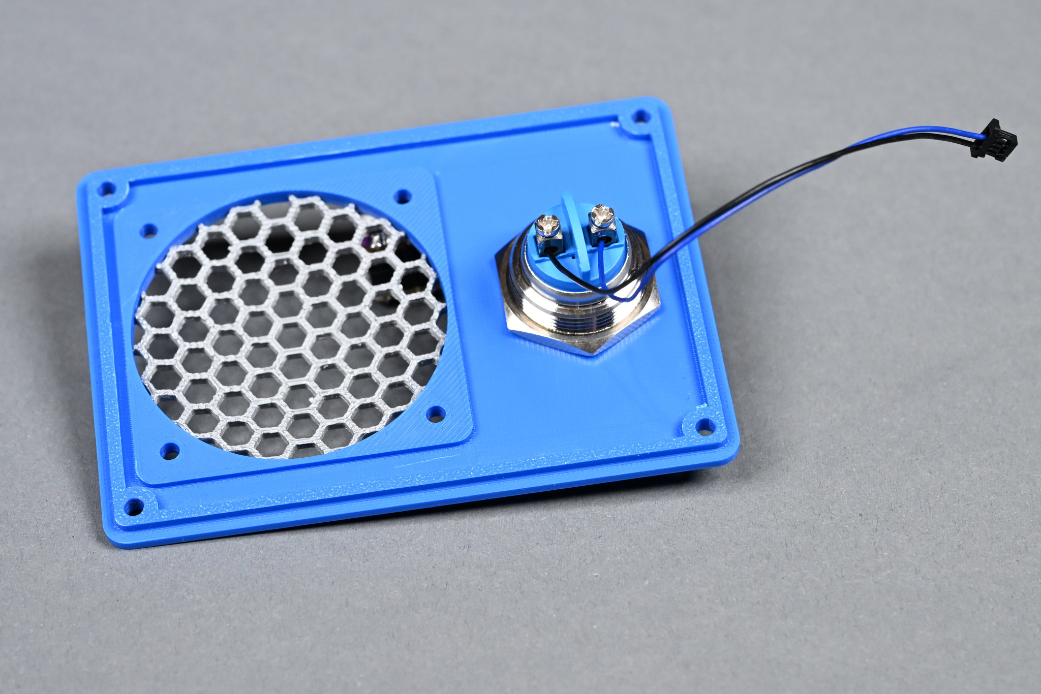
The speaker and button mounted to the lid.
Use four of the M3 x 8 mm screws, washers, and nuts to mount the speaker to the lid. Mount the speaker with the terminals oriented down toward the pushbutton.
10) Mount the USB connector to the base and route the cable
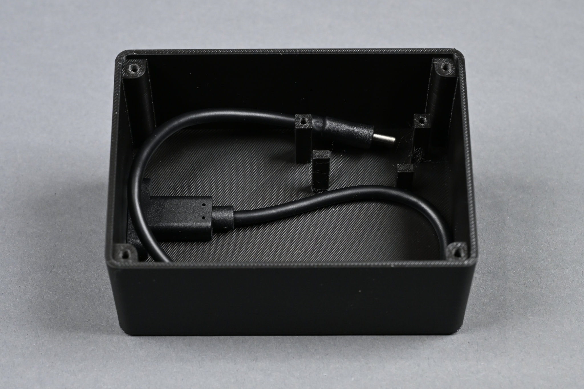
USB C jack mounted and cable routed.
Use two more of the M3 x 8 mm screws to mount the USB C extension to the enclosure. Route the cable as shown in the photo above.
11) Connect all the cables and place the electronics inside their spot in the box
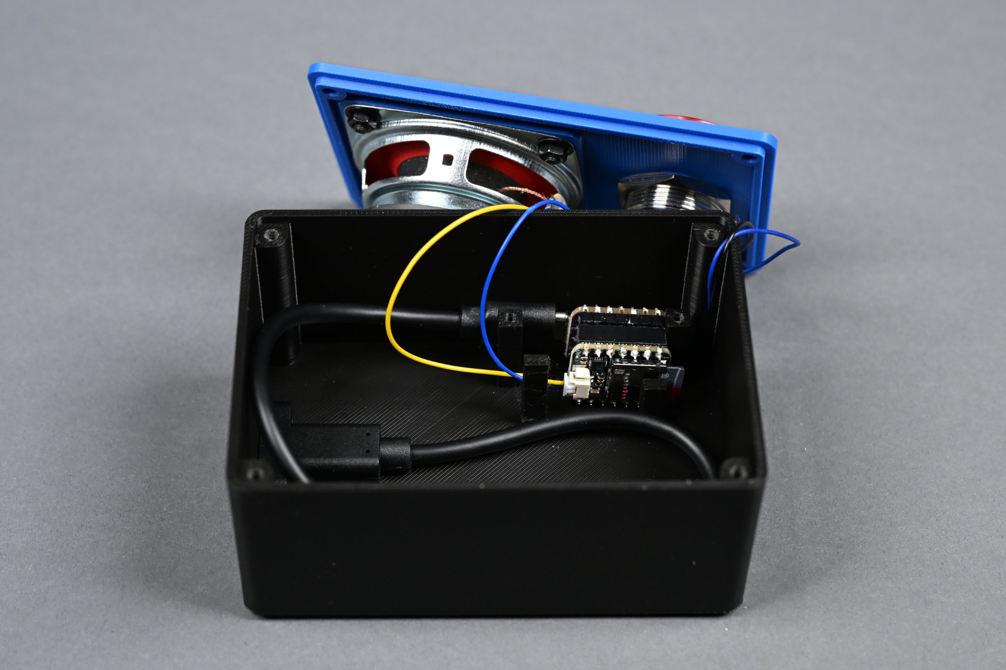
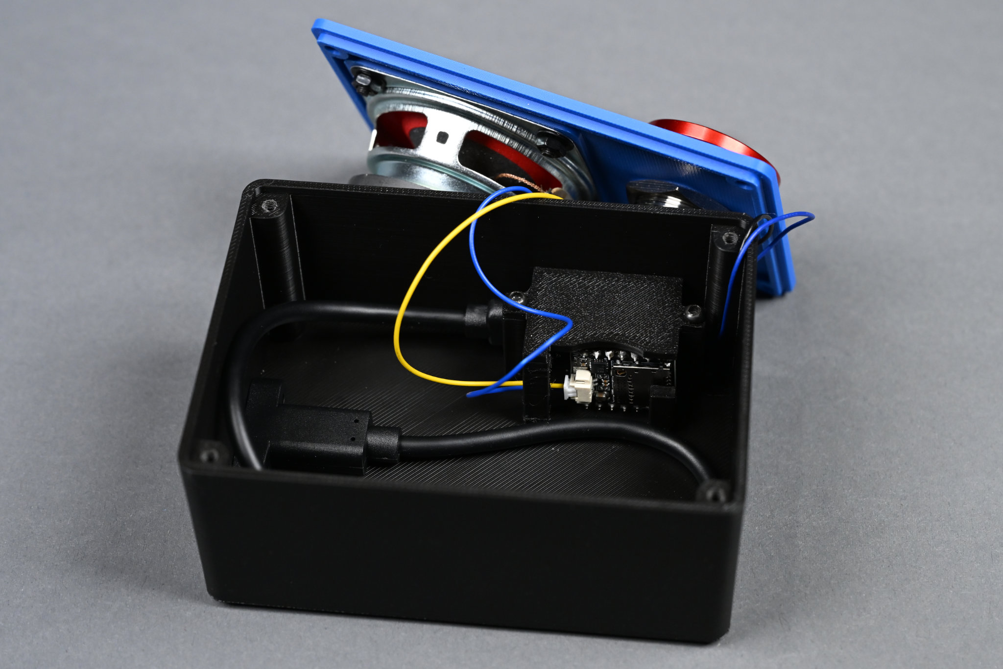
Electronics in place.
Reconnect the pushbutton and speaker to the electronics, place the electronics in the box, and connect the USB C extension to the QT Py board.
12) Place the cover on the electronics
The cover holds the electronics in place and keep things from shorting out.
Place the cover on the electronics and secure it using the two M2.5 x 8 mm screws. PLA is not the best for holding threads so be careful not to over tighten!
13) Mount the lid to the box
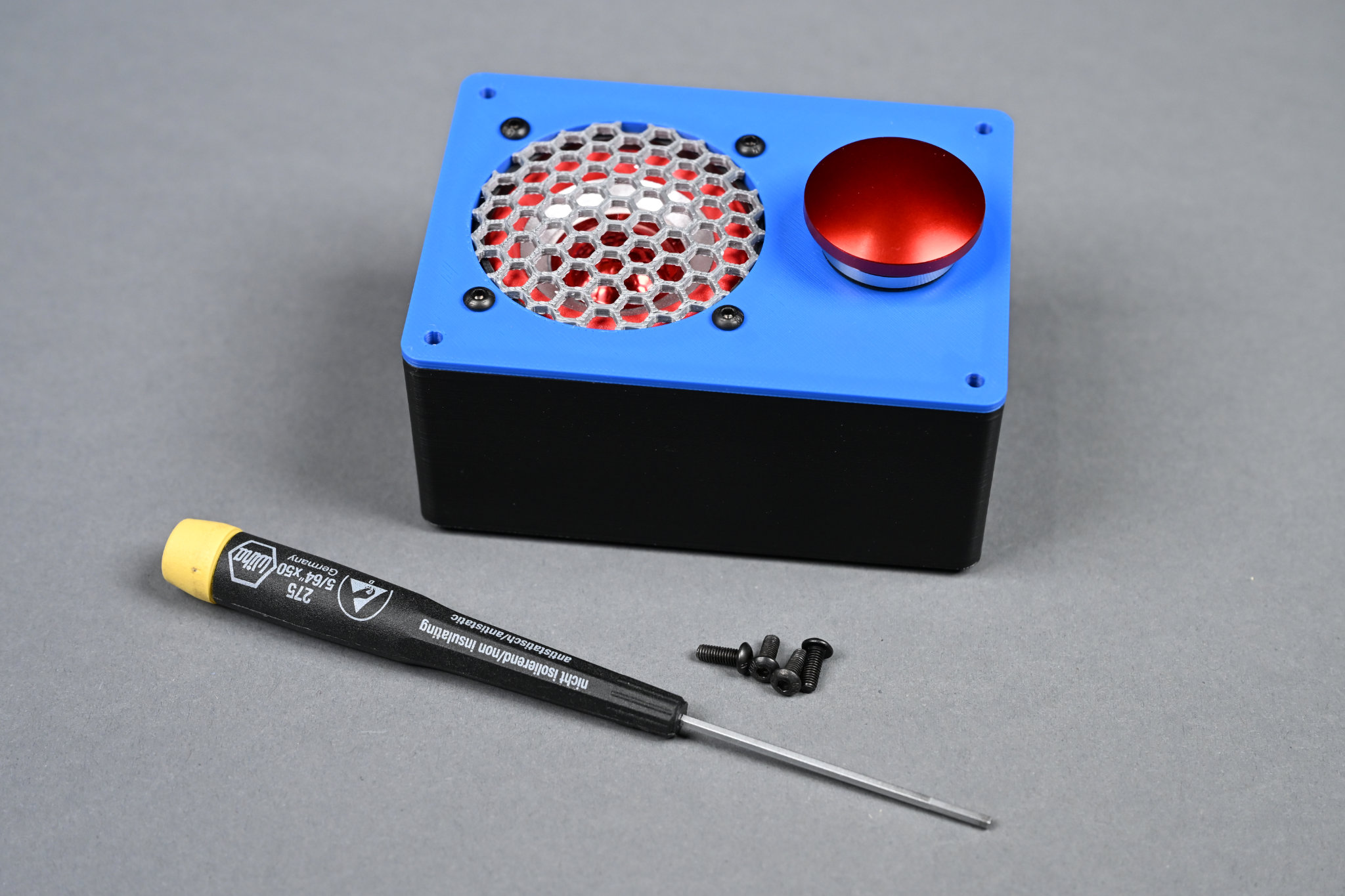
Just four more screws to go.
Place the lid on the box and use the last four M3 x 8 mm screws to mount the lid to the box. PLA is not the best for holding threads so be careful not to over tighten!
14) Test and Enjoy
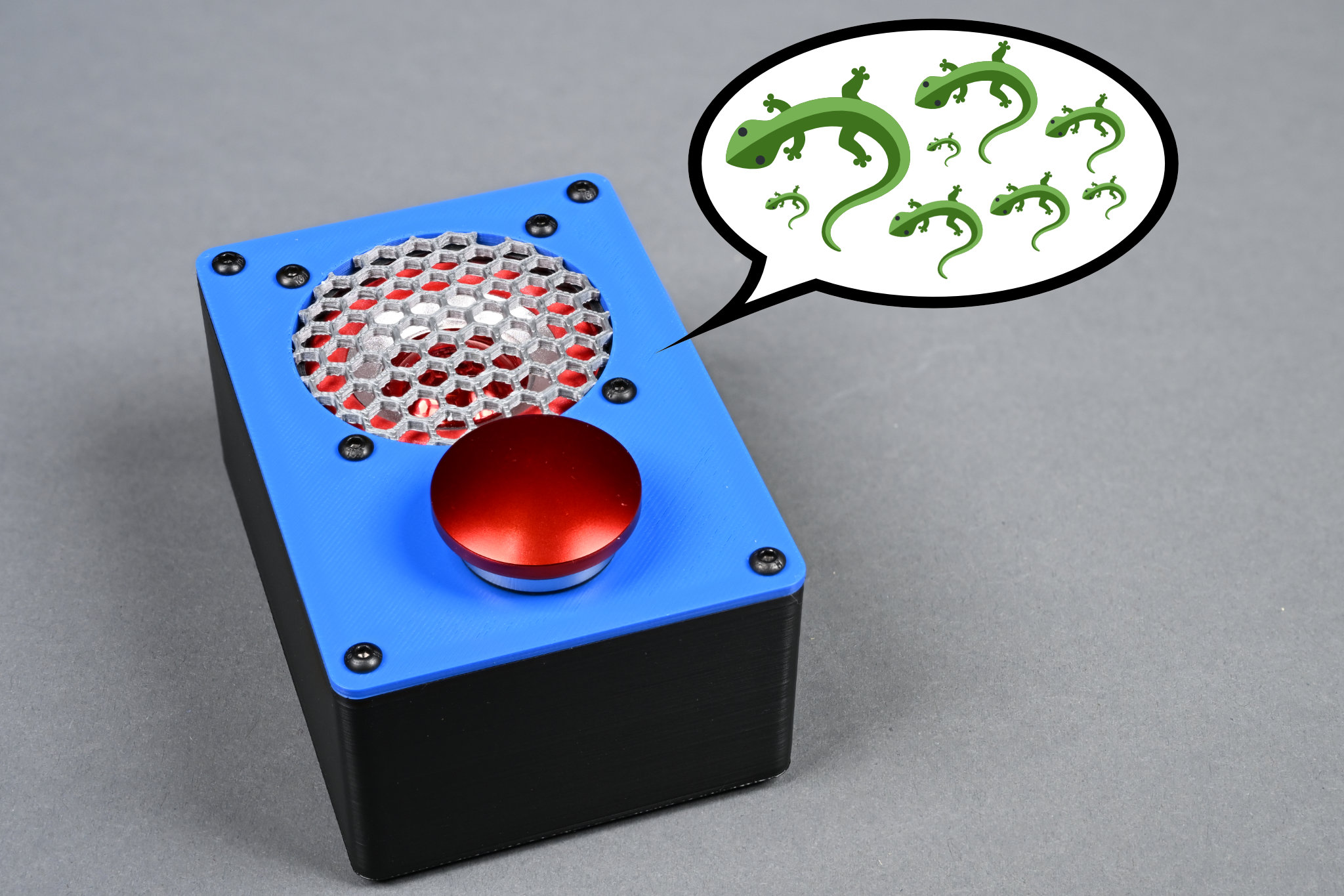
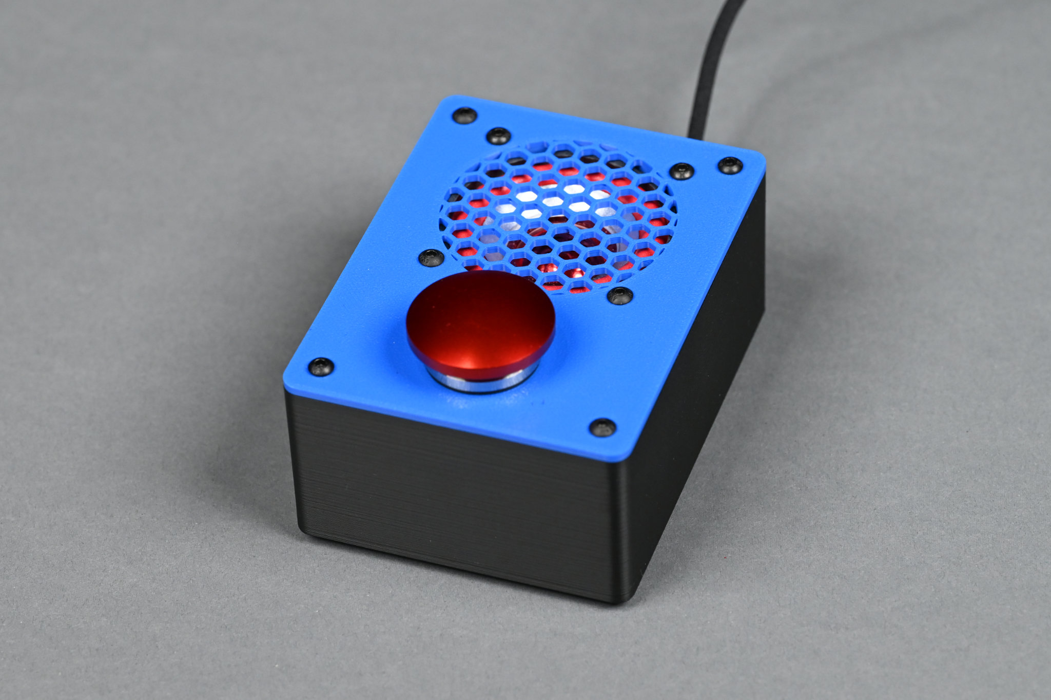
The completed project. Enjoy infinite lizards at the push of a button!
The completed project. Enjoy infinite lizards at the push of a button!
The Software
This project uses a short CircuitPython script for the software. The script waits for a button push then plays a random wave file from either the dev board’s built-in flash or from a microSD card inserted in the Audio BFF board. If the button is pressed while a file is playing, the playing file is interrupted and a new random wave file is started.
Install CircuitPython
Follow the steps to install CircuitPython from the CircuitPython download pages for the selected dev board:
- Adafruit QT Py RP2040
- Adafruit QT Py ESP32-S3 4MB Flash / 2MB PSRAM
- Adafruit QT Py ESP32-S3 8MB Flash / No PSRAM
Install the Adafruit Audio BFF Example and Add Wave Files
Follow the steps in the Adafruit Audio BFF Learning Guide to install the sd card folder, wave files, libraries, and CircuitPython script.
Once the script works using the dev board’s built-in button, change the button line to use the SDA1 GPIO instead of the built-in button GPIO:
button = digitalio.DigitalInOut(board.SDA1)
Now pressing the big red button should trigger the playback of sounds!
Change When Sounds Can Start (Optional)
I wanted pressing the button a 2nd time while a sound is already playing to interrupt the currently sound and begin a new one. This was a relatively easy change to the code. Delete the else: and shift the lines of code below the else four spaces to the left:
    if not button.value:
        if mixer and mixer.voice[0].playing:
            print("stopping")
            mixer.voice[0].stop()
            if wavefile:
                wavefile.close()

        wavefile, wave = open_audio()
        mixer = audiomixer.Mixer(voice_count=1,
                                 sample_rate=wave.sample_rate,
                                 channel_count=wave.channel_count,
                                 bits_per_sample=wave.bits_per_sample,
                                 samples_signed=True)
        mixer.voice[0].level = 0.1
        audio.play(mixer)
        mixer.voice[0].play(wave)
Add Code to Debounce the Pushbutton (Optional)
After changing how quickly sounds could start and stop, I noticed that sometimes a sound would start twice after just one button press. This is caused by the button contacts bouncing and the CircuitPython script sampling the button input multiple times while the contacts were still bouncing.
To solve this problem, I added a 10 ms delay to the main loop and then added a state machine to debounce the pushbutton. The state machine must see the button down twice in 10 ms to count as a new button press and the state machine must then see the button up twice in 10 ms to count as a button release. This solved the button bounce problem.
To add debouncing to the script, add the following variable and function definition between the open_audio function and the start of the while loop:
button_state = 0

def debounce (state, button_value):

  new_press = False

  if state == 0:
    if button_value == False:
      state = 1
  elif state == 1:
    if button_value == False:
      state = 2
      new_press = True
    else:
      state = 0
  elif state == 2:
    if button_value == True:
      state = 3
  elif state == 3:
    if button_value == True:
      state = 0
    else:
      state = 2

  return state, new_press
Then change:
if not button.value:
To:
    time.sleep (0.01)
    button_state, button_pressed = debounce (button_state, button.value)

    if button_pressed:
Finally, from the end of the script, delete:
        while not button.value:
            pass
Code Listing
The final version of the example code with my changes is listed below:
# SPDX-FileCopyrightText: 2023 ladyada for Adafruit Industries
#
# SPDX-License-Identifier: MIT

# Demo audio player that plays random wav files from internal storage or
# SD card. Default pinout matches the Audio BFF for QT Py S2, S3 and RP2040

import os
import random
import audiocore
import board
import audiobusio
import audiomixer
import adafruit_sdcard
import storage
import digitalio
import time

card_cs = digitalio.DigitalInOut(board.A0)
card_cs.direction = digitalio.Direction.INPUT
card_cs.pull = digitalio.Pull.UP
sdcard = None

DATA = board.A1
LRCLK = board.A2
BCLK = board.A3
audio = audiobusio.I2SOut(BCLK, LRCLK, DATA)
mixer = None

button = digitalio.DigitalInOut(board.SDA1)
button.switch_to_input(pull=digitalio.Pull.UP)

button_state = 0
wavefile = 0

wave_files = []
for filename in sorted(os.listdir("/")):
    filename = filename.lower()
    if filename.endswith(".wav") and not filename.startswith("."):
        wave_files.append(filename)


def open_audio():
    n = random.choice(wave_files)
    print("playing", n)
    f = open(n, "rb")
    w = audiocore.WaveFile(f)
    return f, w


def debounce (state, button_value):

  new_press = False

  if state == 0:
    if button_value == False:
      state = 1
  elif state == 1:
    if button_value == False:
      state = 2
      new_press = True
    else:
      state = 0
  elif state == 2:
    if button_value == True:
      state = 3
  elif state == 3:
    if button_value == True:
      state = 0
    else:
      state = 2

  return state, new_press


while True:
    if not sdcard:
        try:
            sdcard = adafruit_sdcard.SDCard(board.SPI(), card_cs)
            vfs = storage.VfsFat(sdcard)
            storage.mount(vfs, "/sd")
            print("Mounted SD card")
            wave_files = ["/"+file for file in os.listdir('/') if file.endswith('.wav')]
            wave_files += ["/sd/"+file for file in os.listdir('/sd') if file.endswith('.wav')]
            print(wave_files)
        except OSError:
            pass

    time.sleep (0.01)
    button_state, button_pressed = debounce (button_state, button.value)

    if button_pressed:
        if mixer and mixer.voice[0].playing:
            print("stopping")
            mixer.voice[0].stop()
            if wavefile:
                wavefile.close()

        wavefile, wave = open_audio()
        mixer = audiomixer.Mixer(voice_count=1,
                                 sample_rate=wave.sample_rate,
                                 channel_count=wave.channel_count,
                                 bits_per_sample=wave.bits_per_sample,
                                 samples_signed=True)
        mixer.voice[0].level = 1.0
        audio.play(mixer)
        mixer.voice[0].play(wave)
Conclusion
This was a fun project, I learned a bit more Autodesk Fusion, and got some more Python experience while building it.
Two notes on board selection:
- I found that the QT Py ESP32-S3 audio would pop if ending a sound effect early while the QT Py RP2040 would not. For this reason, I would recommend using the QT Py RP2040 for this project unless Wi-Fi is absolutely needed.
- I also found that audio is quicker to start after a button press, at least for the QT Py ESP32-S3 board, if using the microSD card rather than the dev board’s on-board flash for the audio files. For this reason, I’d recommend using the Audio BFF with a microSD card over the I2S Amplifier BFF. I haven’t tested using the QT Py RP2040’s on-board flash to see if it faster than
A complete list of the bill of materials and design files follows.
Bill of Materials
Electrical Parts
- button
- qwicc cable
- qt py rp2040
- audio bff for qt py
- microsd card
- picoblade cable
- speaker
- usb c panel mount cable
- headers and header sockets to connect boards together
Mechanical Parts
- 2 M2.5 x 8mm pan head black oxide screw
- 10 M3 x 8mm pan head black oxide screw
- 4 M3 black oxide hex nut
- 4 M3 black oxide washer
- 4 rubber feet
Filament
3D Printed Parts
Miscellaneous
- speaker foam to stop any rattling
- soldering iron and solder
- flexible usb cables that won’t pull your dev board off your desk
Design Files
Disclaimer: Glen may earn compensation for sales from links on this post through affiliate programs.