
Tired of taking the trash out in the dark? Forgot to turn on the outside lights on the way to the trash cans? Read on to learn how I built a waterproof, battery-powered Zigbee hall-effect sensor to automatically turn on my backyard landscape lights when I open the gate to go into the backyard at night.
Disclaimer: Glen may earn compensation for sales from links on this post through affiliate programs.
Motivation

Me coming home after a night mountain bike ride and having to push some buttons to get some light in the backyard.
In my previous Zigbee project, I built some buttons to control some outdoor lighting. This is great except smart houses shouldn’t require taking extra actions like pressing buttons, opening a phone app, or yelling “Hey, Alexa!” for something to happen. Actions, like turning on a light, should just happen as a part of something you’re already doing.
I wanted my backyard landscape lights to turn on whenever I wheeled the bike into the backyard or took out the trash without me doing anything I wasn’t already going to do. And then I wanted them to turn off when I left the backyard.
To accomplish this goal, I built a battery-powered Zigbee hall effect sensor to turn on my backyard landscape lights whenever the side gate is opened and then turn them off again after the gate is closed.
Why I Couldn’t Reuse My Zigbee Button Board
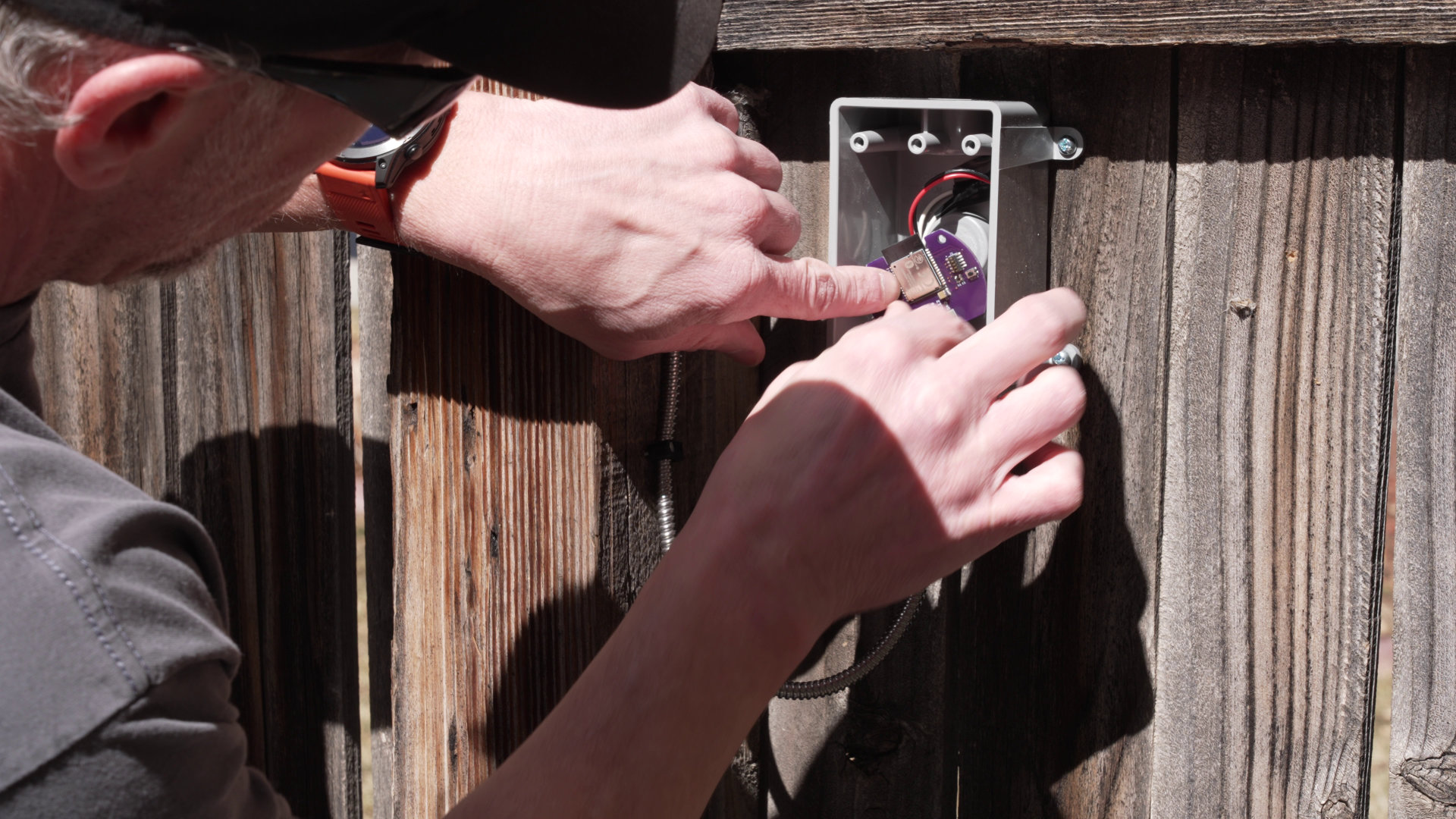
Me connecting a magnetic reed switch to the Zigbee button board from the previous post.
I originally wanted to reuse my Zigbee button board from the previous post. I could pretty easily disconnect the buttons and connect a magnetic reed switch in their place. If I used a normally open sensor, the contacts would be open when the gate is closed and the current consumption of the nRF52840 would be in the microamps.
When the gate is opened, however, the contacts would be closed and the nRF52840’s 13 kΩ weak internal pullup would be connected to ground through the contacts. With a nominally 3 V battery and a 13 k resistor connected to ground, the current consumption would jump to 230 µA or over 50 times higher than when the gate is closed. This would quickly kill the battery life if the gate were left open for any significant period of time. I needed a better solution.
Existing Off-the-Shelf Solutions
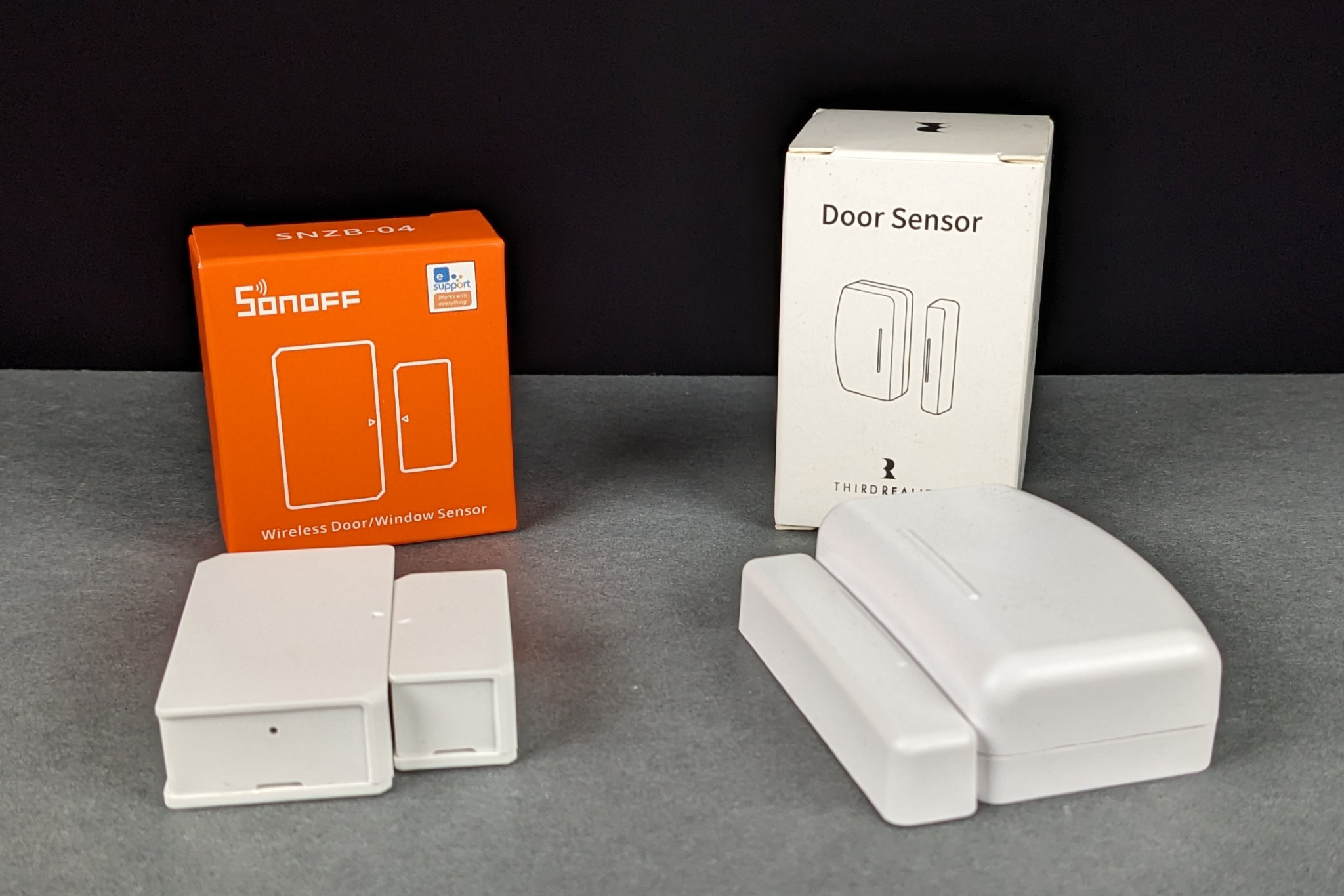
Two off-the-shelf Zigbee door sensors.
I purchased two inexpensive, off-the-shelf Zigbee door sensors to see how these worked and see if I could learn anything from their design.
Sonoff SNZB-04
A Sonoff SNZB-04 wireless Zigbee door sensor.
The first sensor was a Sonoff SNZB-04. It’s powered by a CR2032 coin cell. I took it apart and discovered that it too used a magnetic reed switch. If I remember correctly, it used a 100 kΩ pullup resistor on the board. That’s better than the nRF52840’s 13 kΩ but it would still lead to the gate drawing 5 times as much current in one position as the other. And it’s not waterproof.
Third Reality 3RDS17BZ
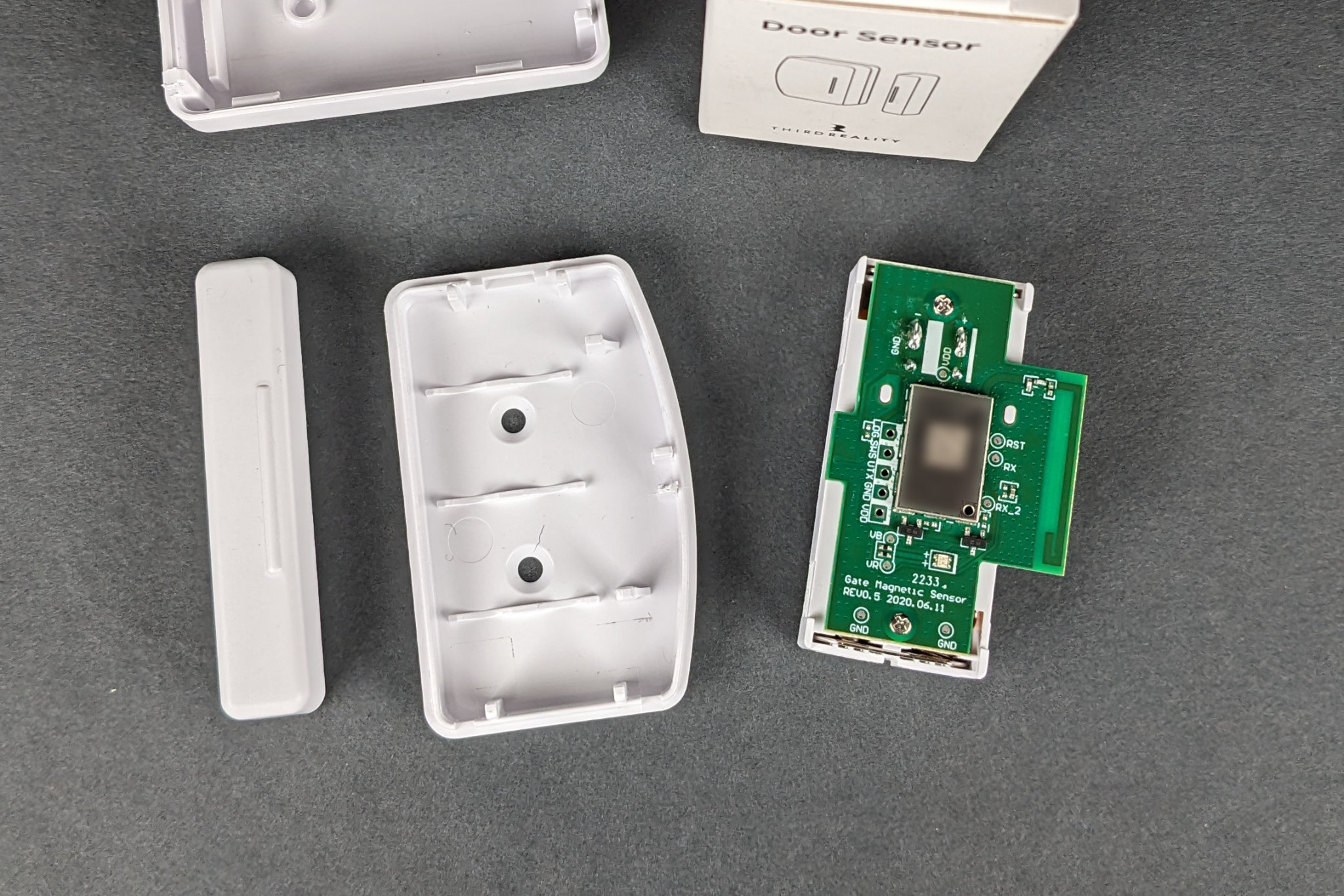
A Third Reality 3RDS17BZ wireless Zigbee door sensor.
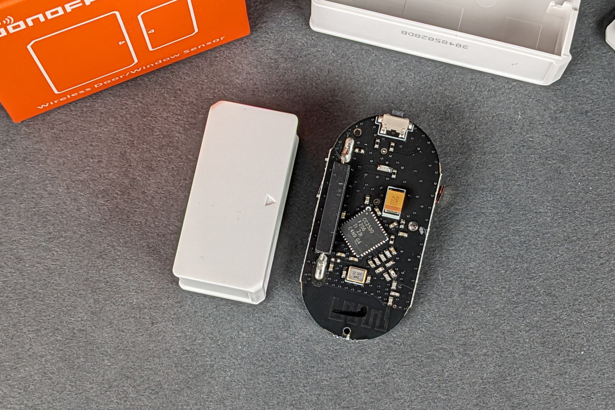
The second sensor was a Third Reality 3RDS17BZ wireless door sensor. It’s powered by a common AAA battery. I disassembled it and quickly noticed there was not a large magnetic reed switch on the board.
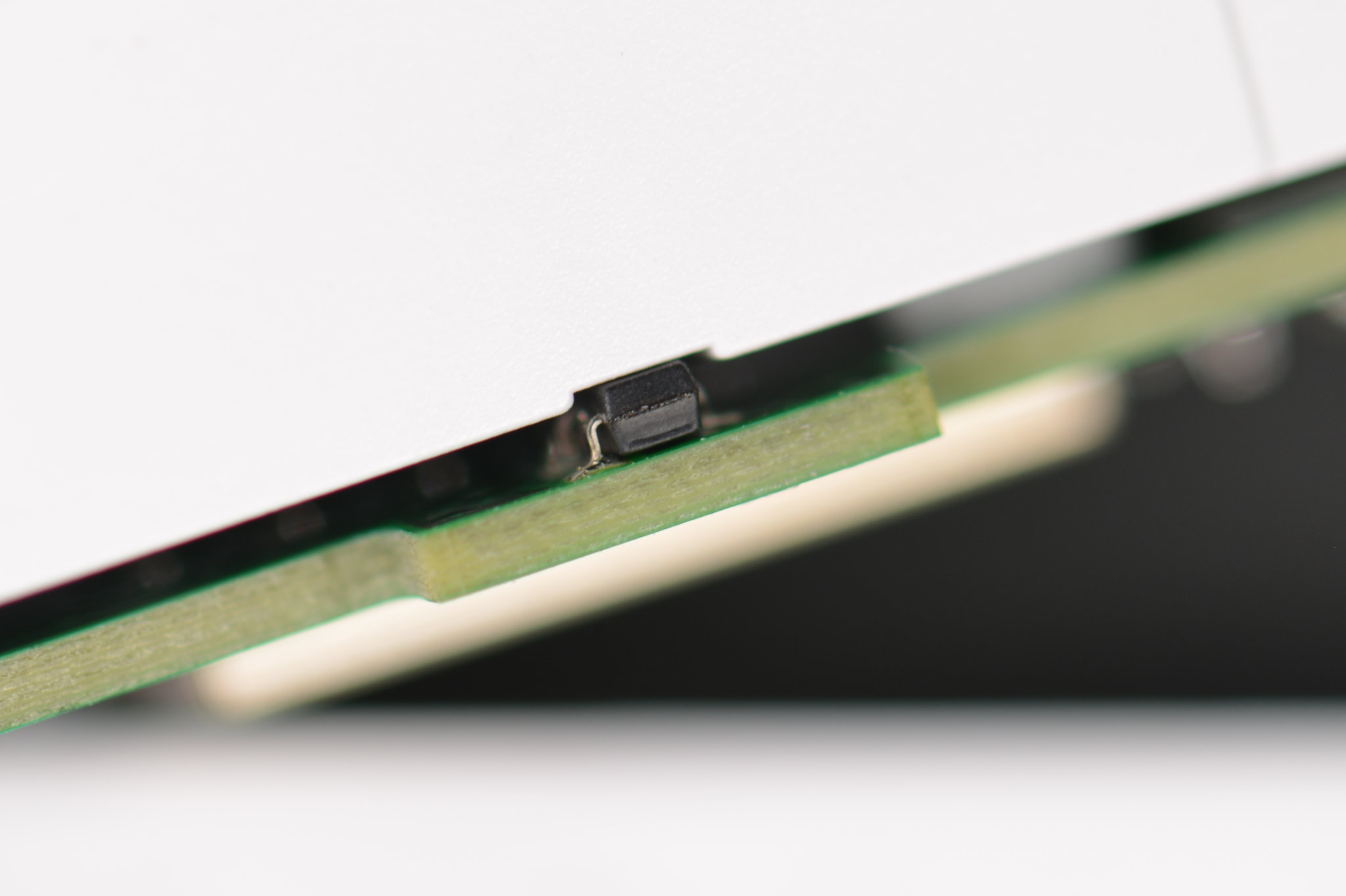
Close up of the Third Reality’s hall effect sensor on the edge of its circuit board.
I looked a little closer at the board edge near where the magnet goes. On the edge was a small device in a 3-pin SOT-23 package. What could it possibly be but a Hall effect sensor! It outputs one logic state when the magnet is close to it and the other logic state when the magnet is not near it.
At this point, I needed to research Hall effect sensors to see what their typical current consumption was. If the Third Reality door sensor was water proof, I likely could have used it as is.
Hall Effect Sensor Test Board
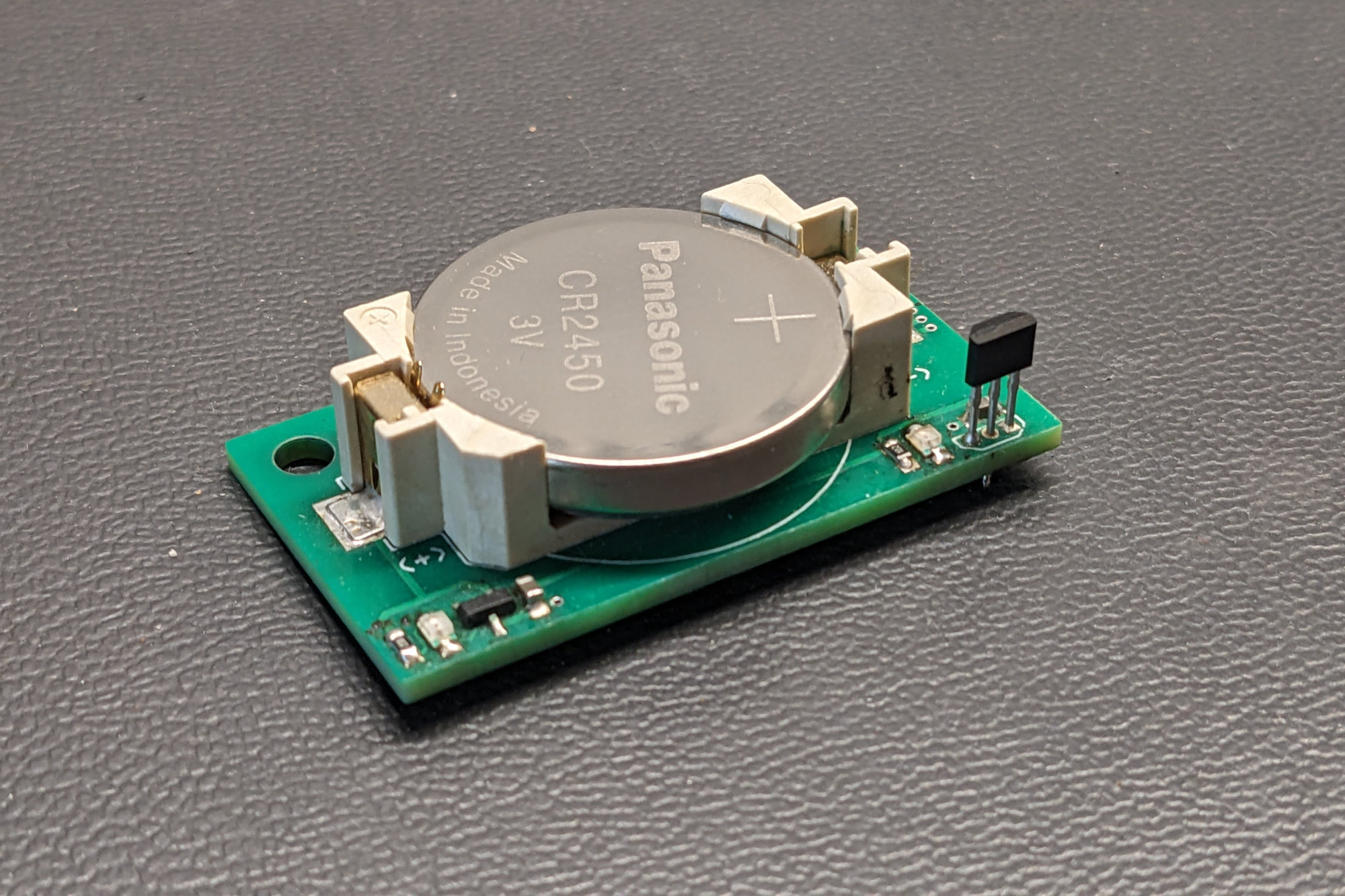
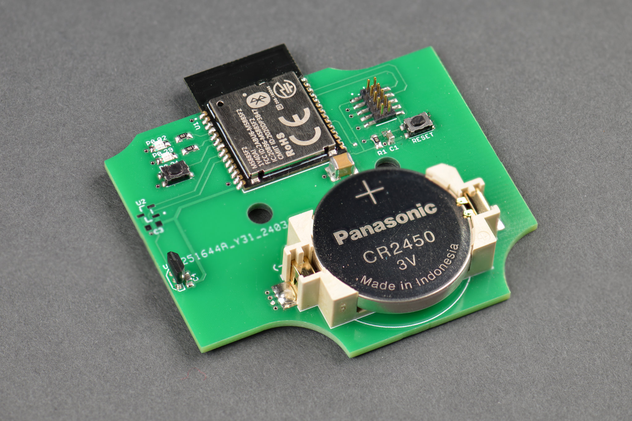
My Hall effect sensor test board with a CR2450 coin cell and two Hall effect sensors from TI. One is in SOT-23-3 SMD package and the other is in a TO-92-3 through-hole package.
After a few hours of research, I found a promising series of Hall effect sensors from TI, the DRV5032FB series. These sensors are available in surface mount and through hole packages, have a current consumption of about 0.5 µA, and have push-pull outputs so I would not need to use the nRF52840’s internal pullups. I quickly designed and built a test board, shown above, to try them out and gauge their suitability for my application.
Schematic
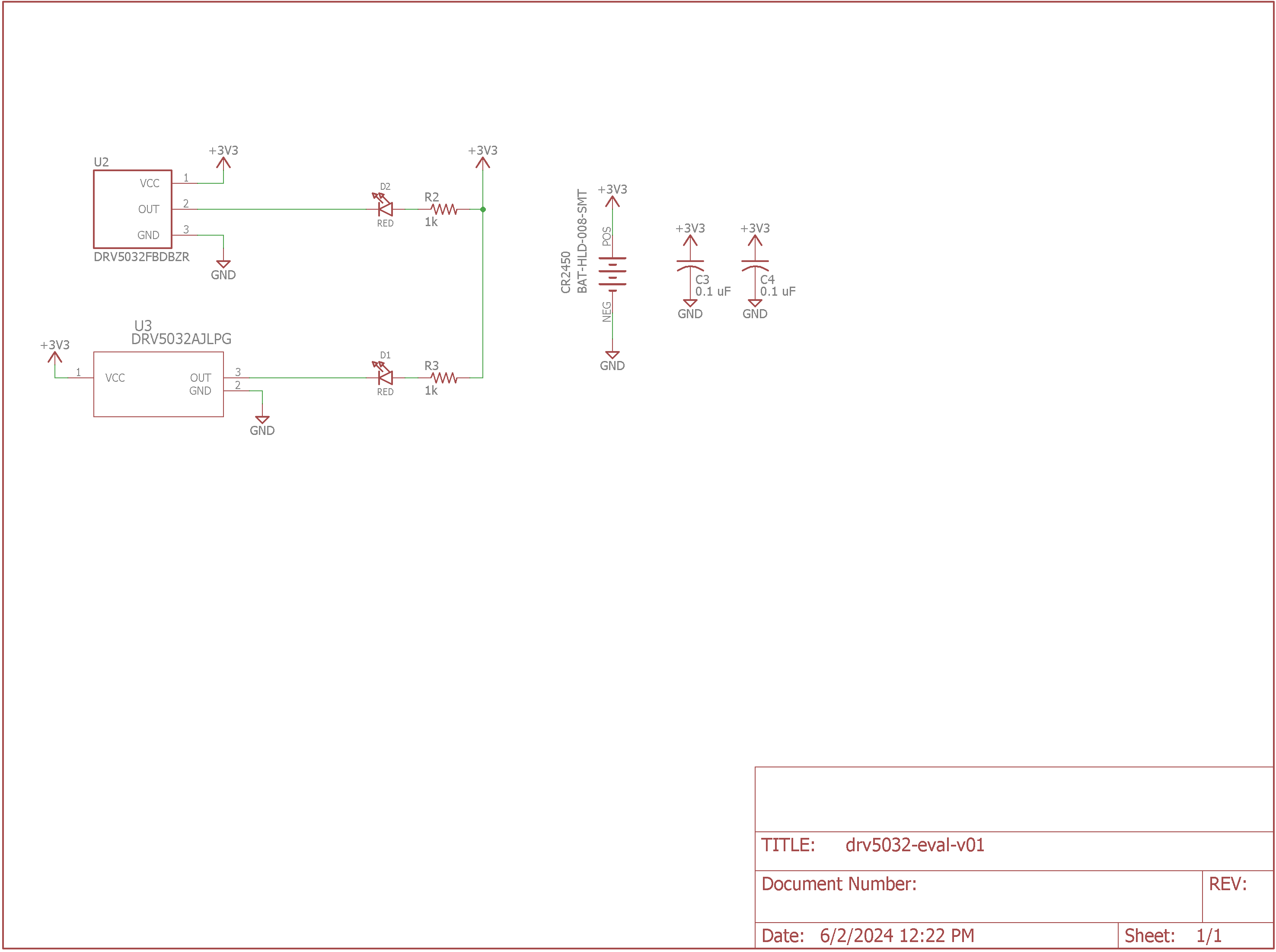
Hall effect sensor test board schematic.
The schematic of the test board is shown above. It’s just a small battery, two sensors with each in a different package, and two low-current LEDs to indicate when a magnetic field has been detected by each of the sensors.
Test Results
Testing the Hall effect sensors with a magnet mounted to the gate.
The results with the test board were promising. Both sensors worked well and detected the presence or absence of the magnet at a sufficient distance to work with the gap between the fence’s gate and the fence’s post.
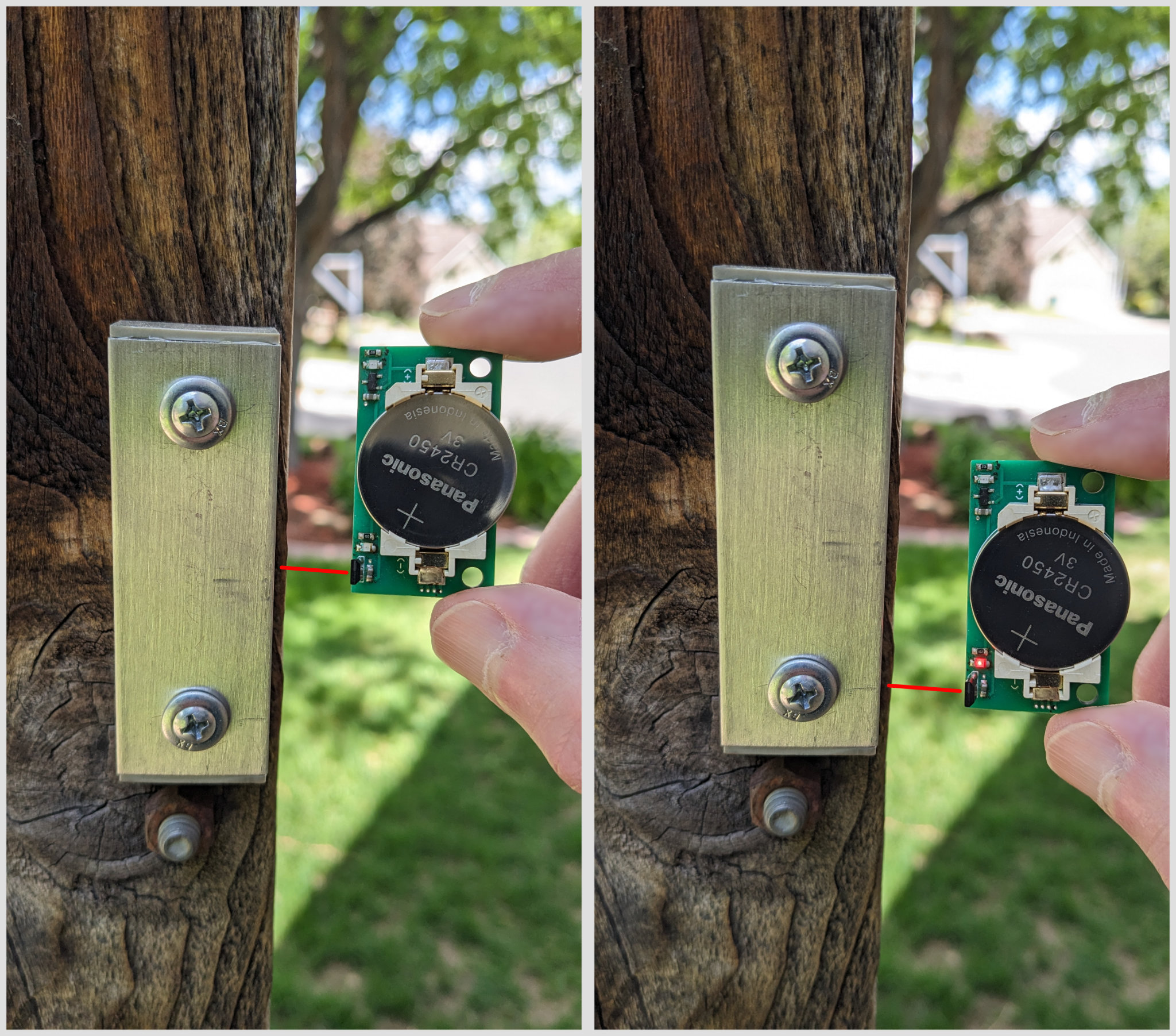
One weird thing is that my magnet’s magnetic field had a big gap in the middle and was strongest at the top and bottom of the magnet rather than in the middle. In the photo above, you can see the magnetic field is not detected when the sensor is centered on the magnet (left) but is detected when it is placed even with the lower screw (right).
Zigbee Gate Sensor Board
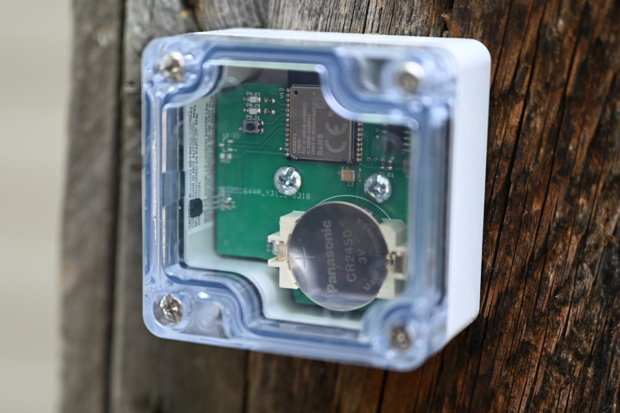
Photograph of the completed Zigbee gate sensor board.
With the hall effect sensor selected and tested, it was time to design the gate sensor board. The completed board is shown above.
Schematic
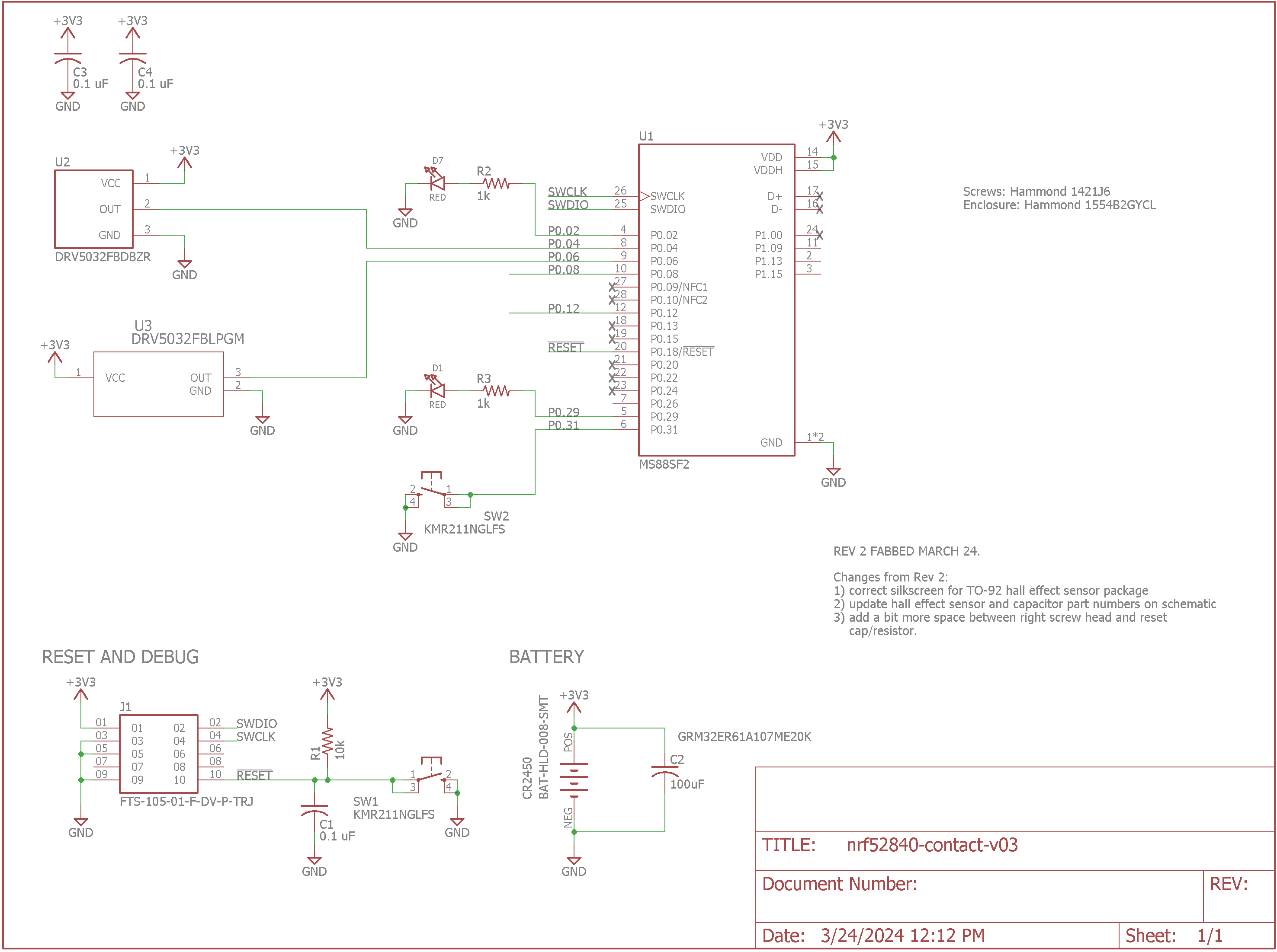
Schematic of the ZIgbee gate sensor board.
The schematic for the gate sensor is shown above. It’s almost identical to the Zigbee button board except the screw terminals for the buttons have been replaced with the option to use either the surface mount or through hole version of the DRV5032FB Hall effect sensors.
The very high integration of the Minew Semiconductor MS88SF2 RF module means there’s not much to the hardware. It’s the RF module plus a few buttons, LEDs, passives, and the sensors. Note that the MS88FS2 is available in three different power configurations. For my battery-powered four-input Zigbee transmitter, I’m using “Configuration 3: 1.8V-3.6V to VDD.”
The Enclosure
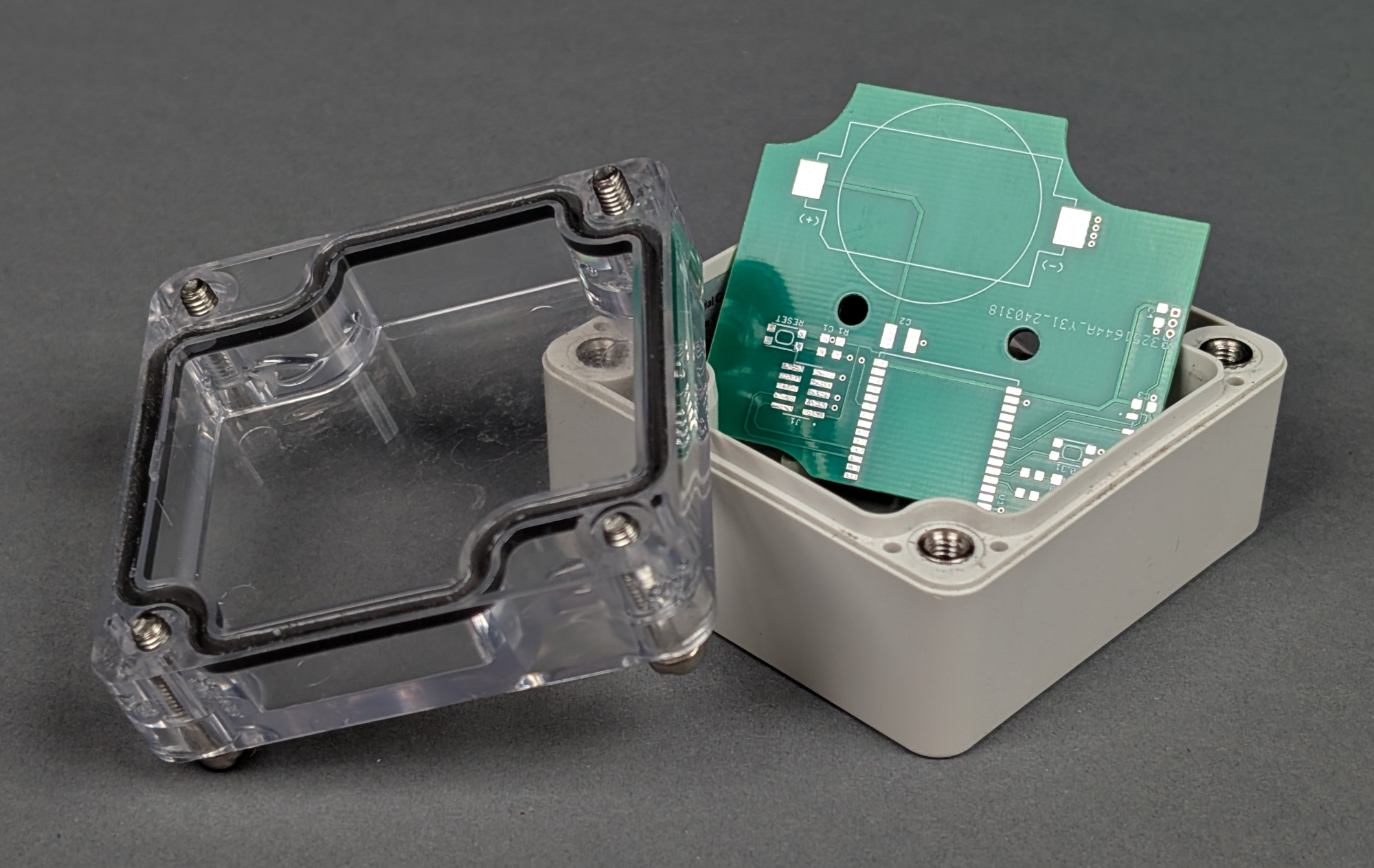
An unstuffed gate sensor board and the waterproof enclosure for it.
The board is a funky shape because I wanted it to fit in the waterproof Hammond enclosure shown above. This is Hammond part number 1554B2GYCL.
Software Development and Current Measurement
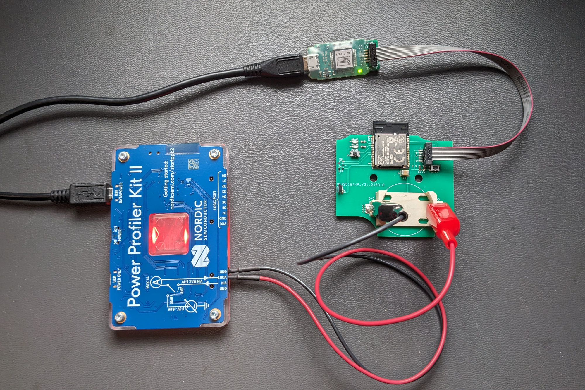
Measuring the boards power consumption using the Nordic Power Profiler Kit II.
The software for this board is almost identical to the software for the four-button Zigbee board. The only material changes were reducing the number of supported buttons from four down to one, disabling the internal pullups on the input connected to the Hall effect sensor, and enabling callbacks on both edges of the input signal.
Once the software was ready, I used the Nordic Power Profiler II to measure the average current consumption of the board over a few 10 minute intervals. The measurement results were:
4.26 μA with no transmissions in a 10 minute period with gate open.
4.00 μA with no transmissions in a 10 minute period with gate closed.
4.27 μA with 2 transmissions in a 10 minute period.
These measurements are inline with my expectations given the current consumption of the previous board and the current consumption spec from the Hall effect sensor’s datasheet.
Software Changes vs My Zigbee Switch Board
The biggest software change was initializing the nRF52840’s input pin that is connected to the Hall effect sensor to generate a callback on both rising and falling inputs. The four button Zigbee sensor listened only for falling edges. A falling edge would wake the CPU and then the CPU would stay active and wait for the rising edge at the input before going back to sleep.
This would waste battery while the gate was closed and the Hall effect sensor’s output was low. To prevent excess current draw when the gate is in the closed position, I reconfigured the input to listen for both edges then sleep as soon as the Zigbee status messages were transmitted.
Now, when the gate is opened, the Hall effect sensor’s output goes high and a rising edge is detected by the nRF52840. This wakes the CPU, the CPU sends a gate opened message, then goes back to sleep. Then, when the gate is closed, the Hall effect sensor’s output goes low and a falling edge is detected by the nRF52840. This wakes the CPU, the CPU sends a gate closed message, then goes back to sleep.
Installation
The completed Zigbee Hall effect gate sensor mounted to the fence post.
I mounted the sensor to the fence post opposite the post with the gate’s hinges.
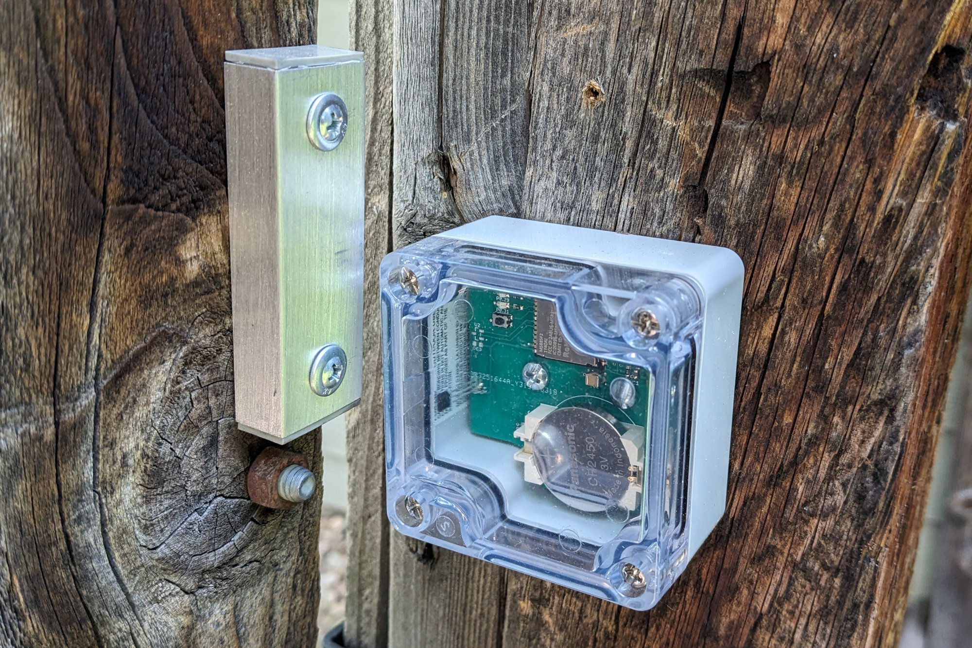
The magnet mounted to the gate and the sensor mounted to the fence post. Note the strange position of the magnet relative to the sensor. The need for the offset was discussed in a previous section of this blog post.
Then I mounted the magnet to the opening edge of the gate. I swung the gate open and closed a few times and verified the sensor transmitted messages to the Zigbee coordinator successfully.
The Lights, Transformer, and Z-Wave Outlet
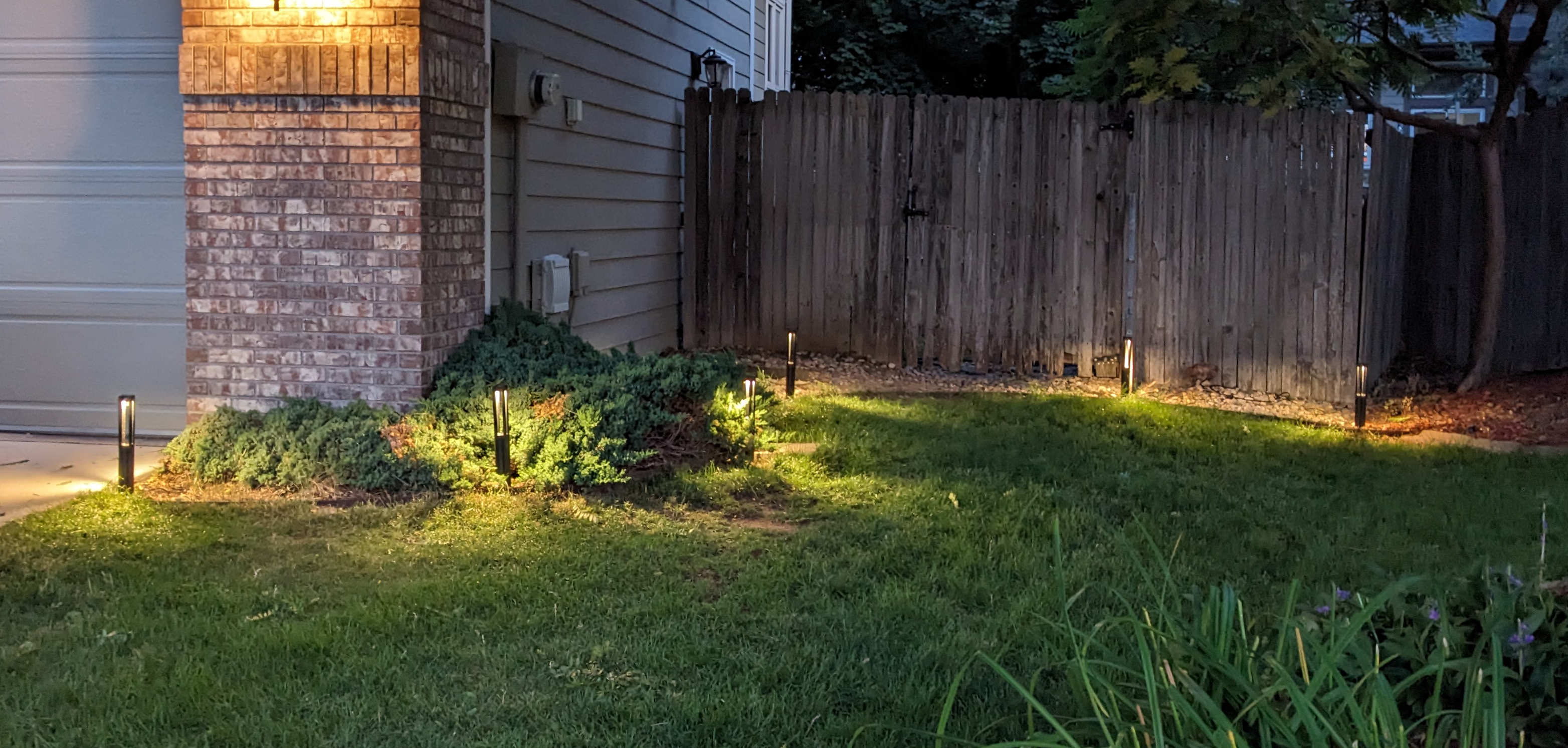
My landscape lights. These are in the front yard.
My landscape lights are simple warm white bollards that run off 12 VAC or 12 VDC. A photo of some of them in the front yard is shown above. I really like that the bulb is at the top of the fixture and projects downward toward the ground rather than outward. They provide sufficient light to see what you’re doing without being blinding.
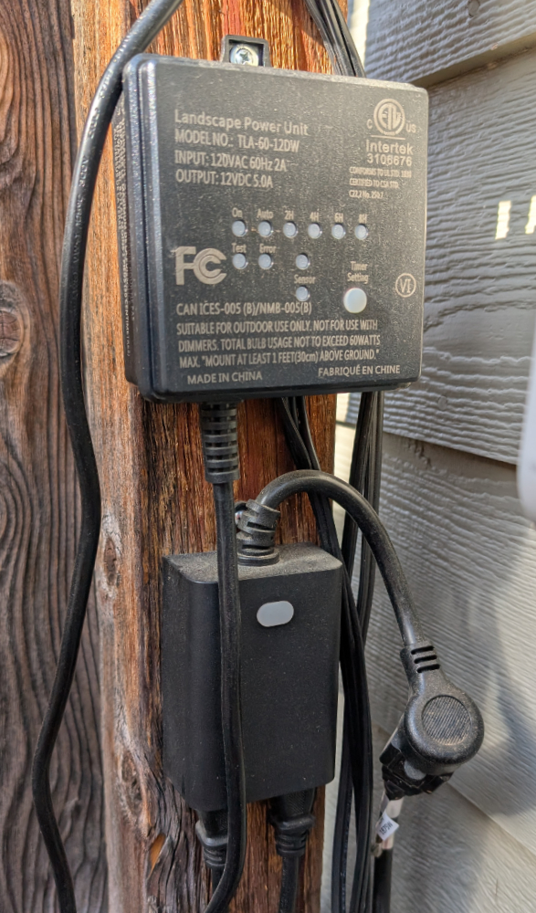
The landscape light transformer and z-wave switched outlet.
They’re connected using 16 AWG wire and insulation-displacement connectors to a low-voltage landscape lighting transformer from Dewenwils. The transformer is set to its “constant” mode so that the lights are always on when the transformer is powered.
To switch power to the transformer and turn the lights on and off when the gate is opened and closed, I use a Zooz ZEN14 outdoor double plug. The Zooz plug is a Z-Wave device so it required installing and running Z-Wave JS UI on the same Raspberry Pi that runs Zigbee2MQTT for the gate sensor.
Tying Everything Together with Python
I could have used Home Assistant to tie everything together but my needs are simple enough that a Python script and an MQTT broker were sufficient to link the Zigbee gate sensor to the to the Z-Wave outlet that controls the lights.
When the gate is opened or closed, my sensor sends a Zigbee message to Zigbee2MQTT and Zigbee2MQTT publishes a gated opened or gated closed message on the rear gate topic to the MQTT broker.
My Python script is subscribed to the rear gate topic on the MQTT broker. When it receives the gate opened message on the rear gate topic it:
- Sends a short gate opened message to my cell phone using pushover.net.
- Takes a photo using a camera above the gate and sends that photo to my cell phone using pushover.net
- Determines if it is between dusk and dawn. If it’s dark outside, it sends an outlet on message on the rear gate outlet topic to the MQTT broker.
When the Python script receives the gate closed message on the rear gate topic, it sends an outlet off message on the rear gate outlet topic to the MQTT broker.
Z-Wave JS UI is subscribed to the rear gate outlet topic. When it receives an outlet on or outlet off message, it will send a Z-Wave command to turn the Zooz outlet for the lights on or off.
The end effect is that if it is dark out, opening the gate creates a Zigbee gate opened message that gets translated by a bunch of software into a Z-Wave outlet on message thus turning on the lights. Then closing the gate creates a Zigbee gate closed message that gets translated into a Z-Wave outlet off message thus turning off the lights.
Conclusion
This was interesting project. The most interesting part, however, is seeing how long the battery lasts. So far, the battery has lasted through a complete year in the Colorado outdoors. This includes a summer with peak temperatures in the 100s and a winter with overnight lows well below 0° Fahrenheit. The sensor and battery have both, in fact, outlasted the gate and fence they were mounted on. The gate and fence will be replaced next month and the sensor will be moved to the new fence to begin year two.
Design files
The design files and nRF52840 software for this project are available on Github in my Zigbee homebrew contact sensor repository.
Disclaimer: Glen may earn compensation for sales from links on this post through affiliate programs.