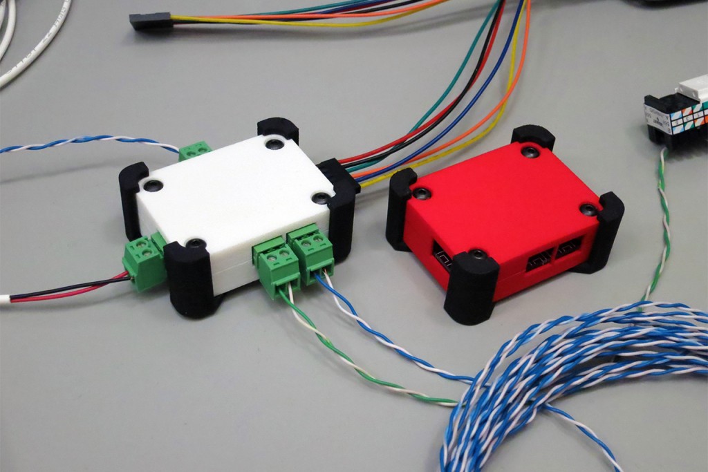
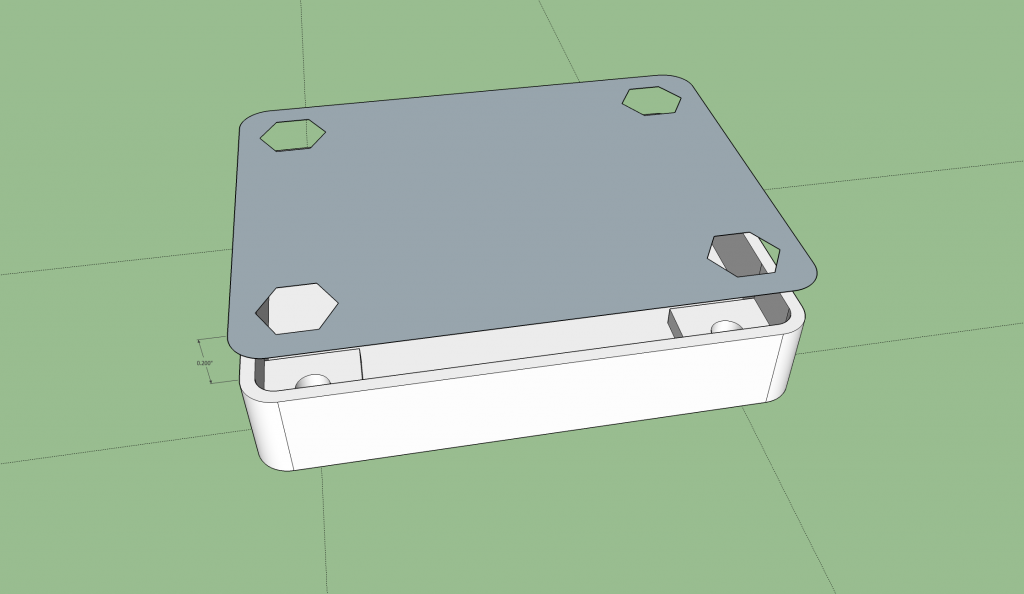
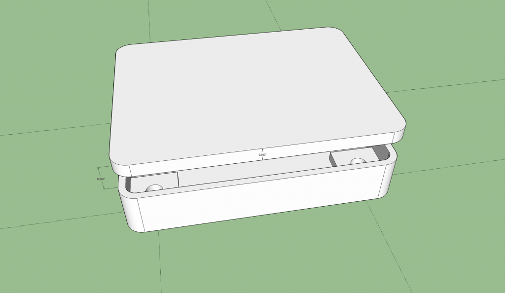
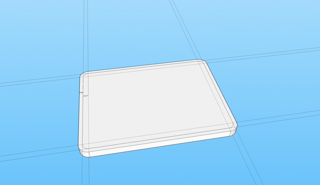
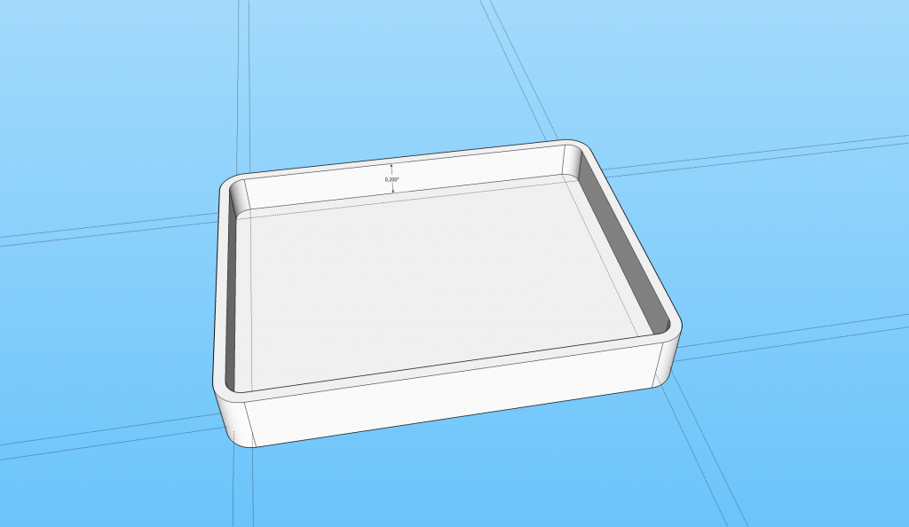
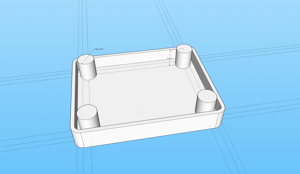
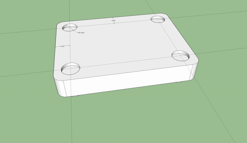
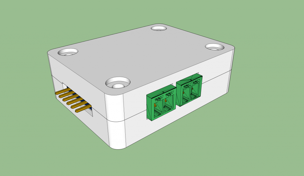
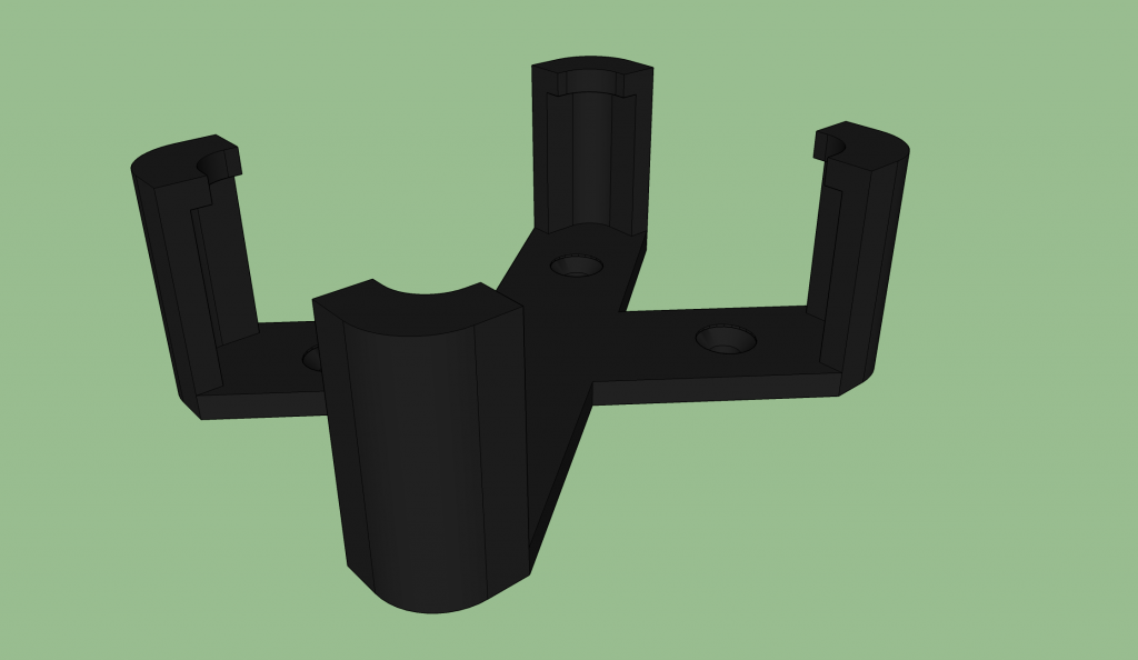
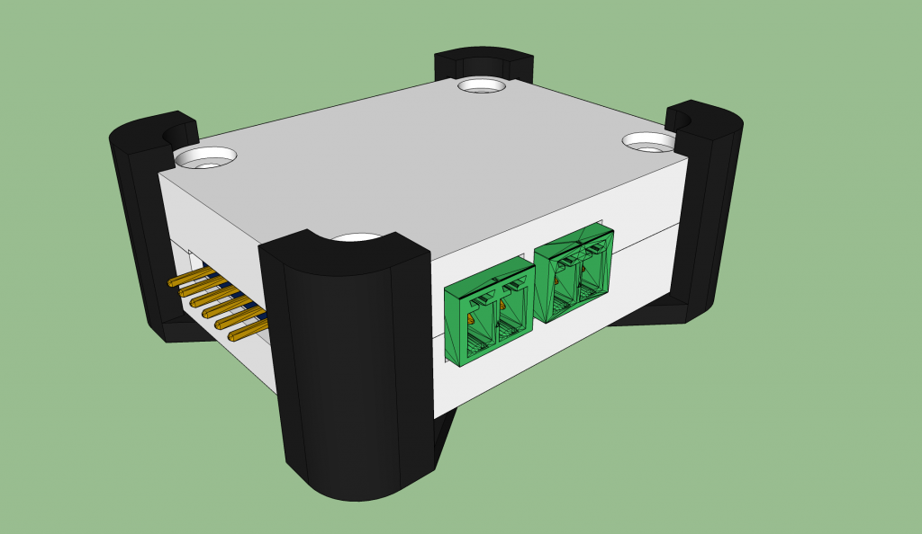
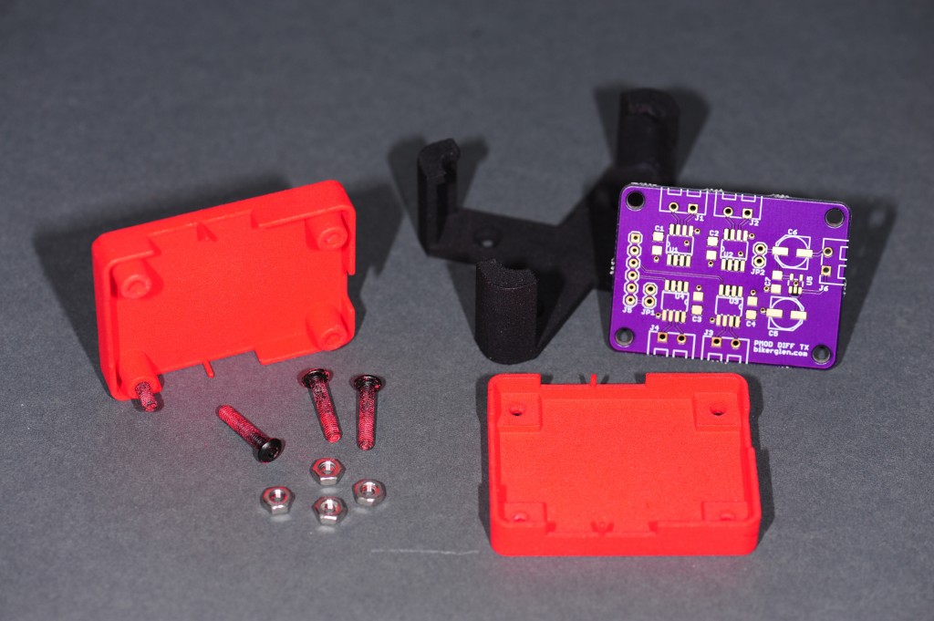
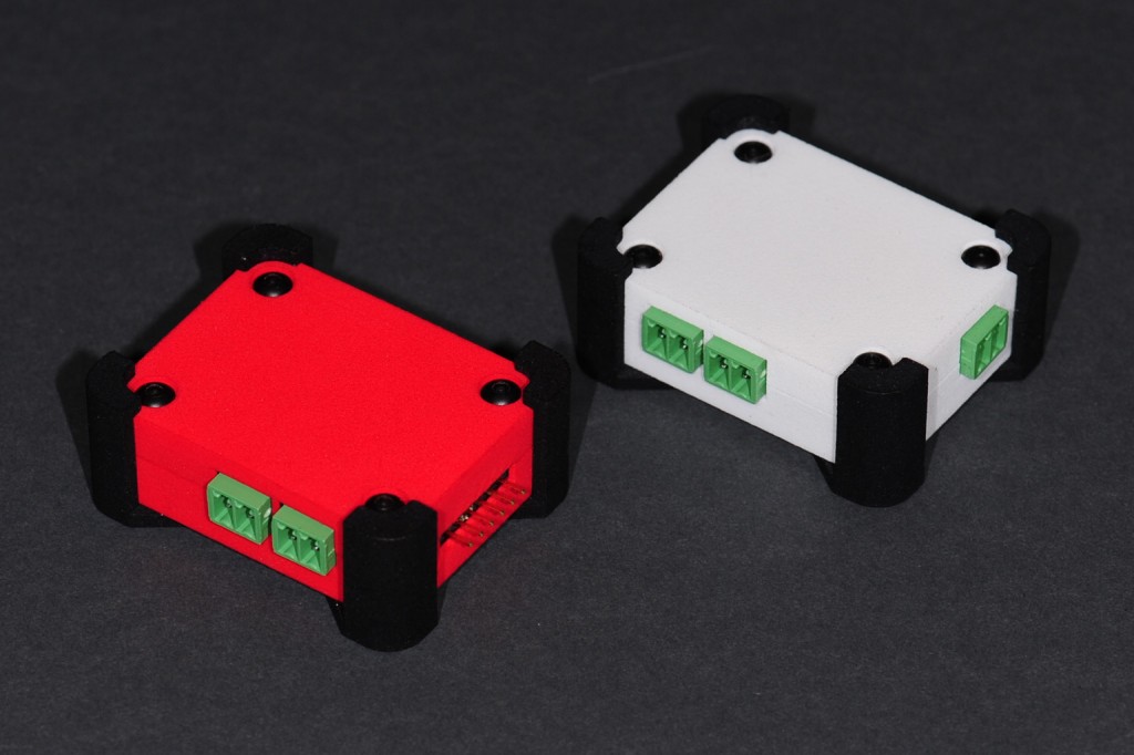
The image above shows two enclosures for a printed circuit board design. These were designed using the inexpensive hobbyist version of CadSoft Eagle and the free maker version of Trimble SketchUp. The free version NetFabb Basic was used to check the design for manufacturing. The enclosures were finally 3D printed at shapeways.com using their EOS Formiga P110 SLS 3D printers. Read on to see some of the lessons I learned while designing and printing these enclosures.
Find or Design a Board
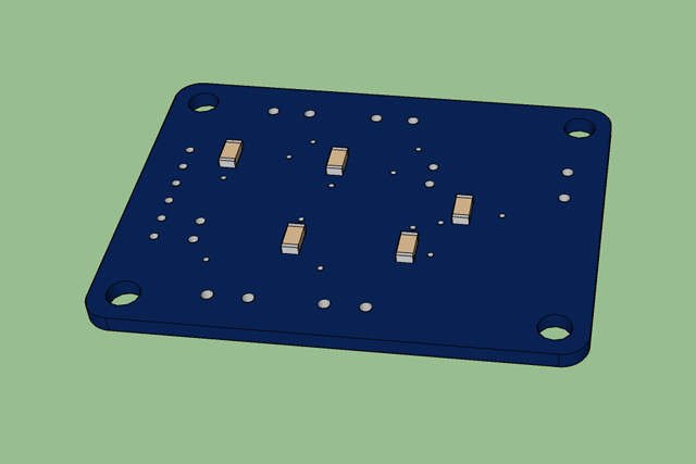
The first step is to find or design a board. The board I used is a quad RS-422 differential transmitter board. It has a Digilent PMOD connector for connecting to an FPGA board and four TI differential transmitters chips that connect to Phoenix Contact terminal blocks. There’s a fifth terminal block for a +5V power input and a power supply on the board as well.
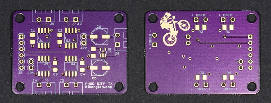
The board to be enclosed. The board uses through-hole components and has 1206 resistors on the reverse side so room for the pins and resistors is needed between the board and the bottom of the enclosure.
At this point, open up the board file in Eagle and note some key measurements.
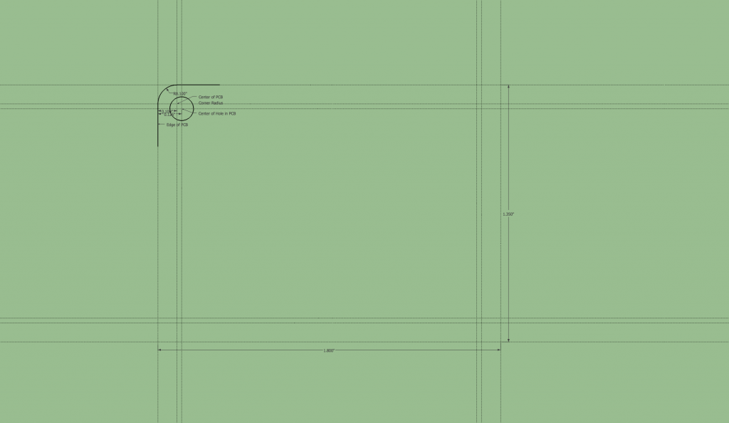
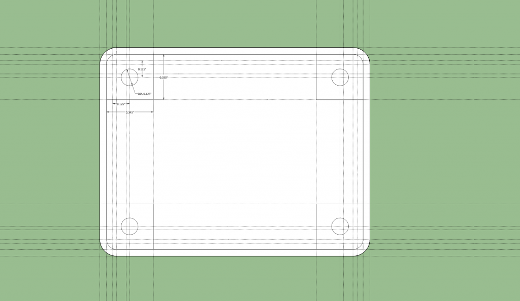
The board measures 1800 by 1350 mil. The holes are 125 mil diameter and are inset 125 mil from each board edge.
Export the Board from Eagle and Import into SketchUp
To export the board from Eagle and import the board into SketchUp requires the set of EagleUp plugins for Eagle PCB and SketchUp. The EagleUp Export ULP script is used from within the Eagle PCB editor to export the board geometry, bill of materials, and component placement information to a .eup file. The .eup file is then imported into SketchUp using the EagleUp Import plugin. Once the plugins are installed, the steps required to perform the export and import are as follows:
- Open the board in Eagle PCB.
- Run the eagleUp_Export.ulp ULP. I’m only interested in the board geometry and parts so I selected the no silk layers and no image options at export. Click OK and the .eup file will be created.
- Launch SketchUp and open a new file. Run the EagleUp Import plugin from the SketchUp Plugins menu on the .eup file created in Eagle. I could only get the EagleUp import plugin to run successfully if I set the model units to decimal millimeters with a precision of 0.001mm.
- Set the model units to the same units used in Eagle. I used decimal inches with a resolution of 1 mil since the board design was done in mils. Measure the board to make sure it is the same dimensions as in Eagle.
At this point, you’ll have a 3D model of your board in SketchUp but a lot of the parts may be missing depending on the parts on your board versus the parts in your 3D component library.
Add Missing Parts
Now to add the missing parts to the board. Search the internet for 3D models of any missing components. You’ll need the components in either .skp or .stl format. Some manufacturers provide 3D models directly on their website. Others you’ll have to find on 3rd party websites. Key components to include are things that impact the dimensions of the enclosure such as the tallest component on either side of the board, and connectors, switches, or indicators that will pierce a wall of the enclosure.
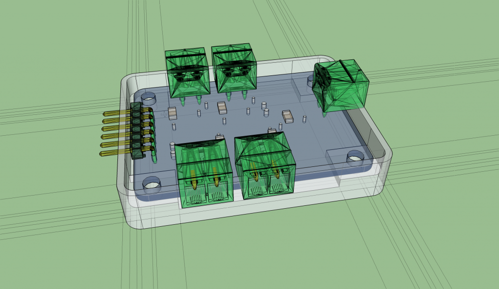
In the case of my board, I added the missing Samtec terminal strip and the five missing Phoenix connectors to the board. I judged the rest of the parts to be inconsequential to the design of the enclosure. After I found the components, I imported the STL for each component and used the move and rotate tools to place the components on the board.
Design the Bottom of the Enclosure
Here are the dimensions used to design the bottom of the enclosure:
| Description | Size | Notes |
|---|---|---|
| Bottom Height | 0.350″ | Somewhat arbitrary but at least sum of bottom thickness and PCB bottom clearance. |
| Bottom Thickness | 0.100″ | Chosen so an M3 nut can be completely recessed into bottom of enclosure. |
| Edge Thickness | 0.050″ | Chosen based on capabilities of 3D printer. |
| PCB Edge Clearance: | 0.045″ | Somewhat arbitrary but at least 0.005″ on each edge. |
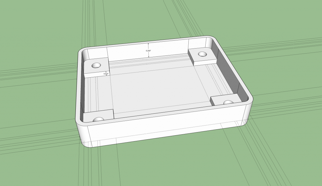
| PCB Bottom Clearance: | 0.075″ | Needs to clear pins on through-hole parts, SMD resistors on back of board. |
| PCB Thickness: | 0.063″ | From the board vendor. |
| M3 Nut Dimensions: | 5.5mm (0.217″) across flats, 2.4mm (.095″) thick. | From the nut vendor. |
Use the tape measure tool to draw some guides to indicate the outline of the PCB board. Remember that this board is 1.800″ by 1.350″ with a 0.100″ corner radius and four 0.125″ diameter holes in the corners inset 0.125″ from each edge.
The enclosure will have 0.050″ thick side walls 0.045″ from the edge of the PCB board. The outside corner radius of the enclosure wall will be 0.125″. The inside corner radius will be 0.075″. These radii will give a wall thickness of 0.050″ in the corners and clear the rounded corners of the PCB. Create guides at the outside wall edges, the inside wall edges, and centers of the corner radii. The picture below shows the upper left corner once the guides are created. Repeat for the remaining corners.
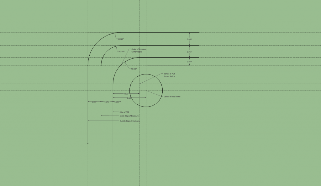
Upper left corner of the guides indicating the enclosure edges. Lines and arcs are for illustration only. Don’t create them yet.
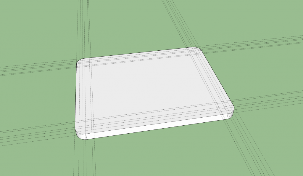
Draw lines and arcs for the outside edges of the enclosure. Use the push/pull tool to pull the resultant plane down into a 0.100″ thick solid.
Now create guides, lines, and arcs for the features on the inside of the bottom of the case. These include the holes for the M3 bolts that will run through both the enclosure and the PCB as well as supports for the bottom of the PCB. I made my supports 0.345″ by 0.335″. These need to clear any components or pins located on the bottom of the PCB.
Use the push/pull tool to extrude the side wall up 0.250″. Use the push/pull tool to extrude each of the PCB supports up 0.075″. After moving the first PCB support up 0.075″, you can double click the remaining three supports to extrude them up by the same amount.
Now that we know where the PCB needs to rest in the enclosure, unhide the PCB and move the bottom face of the PCB to rest on the top face of the PCB supports. Unhiding the PCB will also let you check clearances on the bottom and sides of the board.
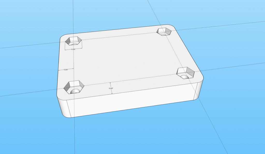
Hide the board and add the nut recesses to the bottom of the enclosure. The nuts are 0.217″ across their flats. If we make the nut recesses 0.270″ across their corners, that will give the recess a distance of 0.234″ across the flats and a clearance on each side of the nut of 0.0085″. The nuts are 0.095″ thick. A recess depth of 0.100″ will allow the nuts to sit flush with the bottom of the enclosure.
The hex extrusions should be centered at 0.220″ from each outside edge to center them on the holes in the PCB and the PCB supports. Lastly, delete the circular planes at the bottom of the hex extrusions to create the 0.125″ holes completely through the bottom of the enclosure.
Group the bottom of the enclosure into its own group. This will prevent the bottom and top of the enclosure from merging into a single blob as we create the top of the enclosure in the next step. The bottom of the enclosure is now complete except for the connector cut outs. We’ll design the top of the enclosure first then make cut outs for the connectors at the end of the design process.
Design the Top of the Enclosure
Here are the dimensions used to design the top of the enclosure:
| Description | Size | Notes |
|---|---|---|
| Top Height | 0.300″ | Chosen to accommodate height of all components and nearest available M3 bolt length. |
| Top Thickness | 0.100″ | Chosen to be same as the bottom of the enclosure. |
| Edge Thickness | 0.050″ | Chosen based on capabilities of 3D printer. |
| PCB Top Clearance: | 0.312″ | Needs to clear all components on top of board. Top clearance is overall enclosure height minus thickness of top and bottom, PCB thickness, and PCB bottom clearance: (0.350+0.300) – (0.100+0.100+0.063+0.075) = 0.312″. |
| Available M3 Bolt Lengths: | 12mm, 15mm (less common), 16mm | Threaded length excluding bolt head; from bolt vendor. |
Double click into the bottom enclosure group, orbit to view the bottom of the enclosure, and select the plane forming the bottom of the enclosure. Right clock and select the bounding edges. Copy the bottom plane and connected edges to the clipboard then exit the group. Paste the edges 0.200″ above the top of the bottom of the enclosure.
Delete the hexagonal holes and extrude the plane up 0.100″ to form the top of the enclosure.
Hide the enclosure bottom and orbit the camera to view the bottom of the enclosure’s top. Add the outline of the inside wall to the enclosure. This wall is 0.050″ thick and has a corner radius of 0.075″.
Extrude the enclosure wall down (up in the camera view) 0.200″.
Add the internal PCB supports. These are 0.250″ in diameter and centered on the holes in the PCB. Draw guides 0.170″ from each interior edge wall to locate the center of the PCB holes on the lid of the enclosure. Draw a circle with a radius of 0.125 at each of the four intersections and extrude the circle down by the PCB top clearance, 0.312″.
Orbit the view back to the top of the enclosure to add the screw head recesses to the top of the top of the enclosure. These are centered above the holes in the PCB. Draw guides at 0.220″ from the outside edge. Center a circle 0.250″ in diameter on these guides in each corner then extrude the circle downward 0.050″. The diameter of the head of the bolt is just under 0.250″ and will fit inside the recess. The bolt head is slightly thicker than 0.050″ and will protrude very slightly from the top of the enclosure.
Add 0.125″ diameter holes all the way through the PCB supports and enclosure top. This is easier to do from the bottom. Draw a 0.125″ diameter circle in the center of each PCB support. Extrude the circle up to the bottom of the recess in the top of the enclosure to from a hole all the way through the PCB support and the top of enclosure.
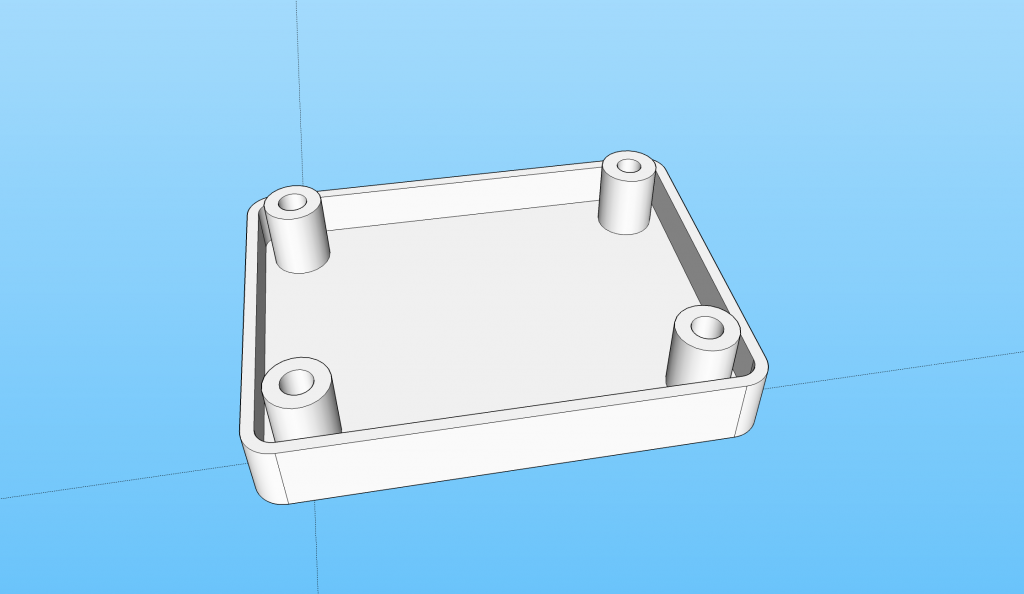
Extrude bolt holes through the PCB supports and top of the enclosure. This is easiest to do from the bottom of the PCB supports.
Group the enclosure top into its own group so that it other entities can be added to the drawing without affecting the geometry of the enclosure top. The top is now complete except for the enclosure cut outs which we will add in a later step. Unhide the bottom of the enclosure and the PCB board.
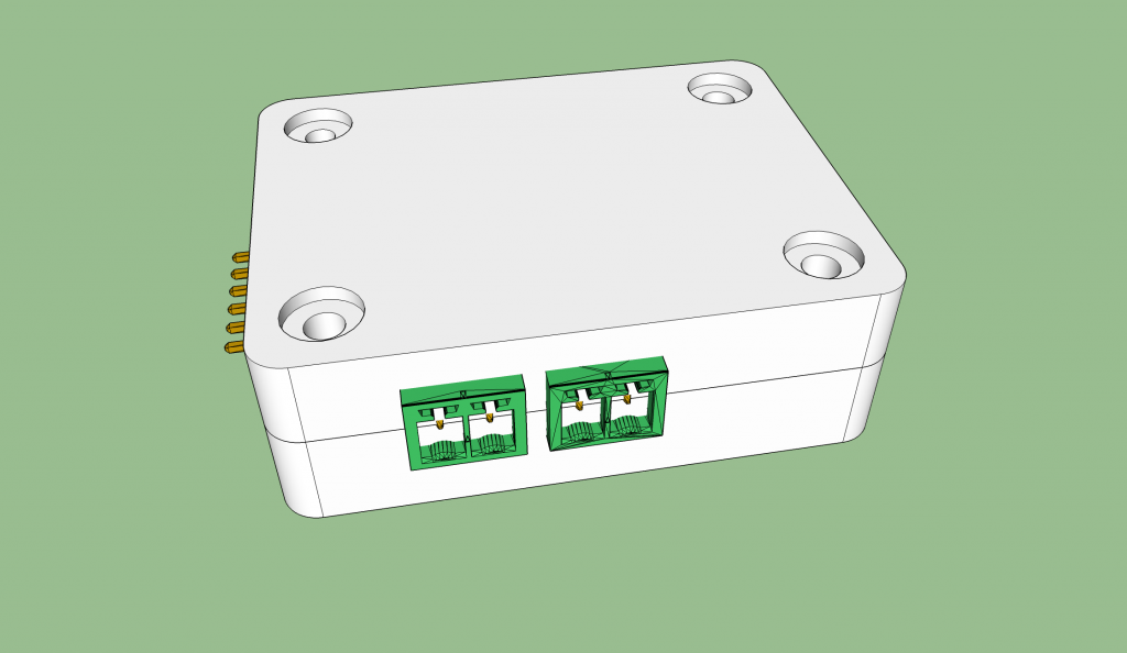
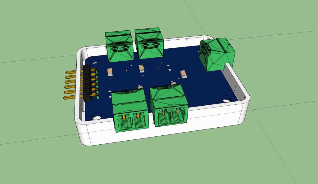
Enclosure top and bottom are complete except for connector cut outs. Verify available bolt lengths will fit your enclosure.
At this point, verify that bolts are available that will extend from the bottom of the recess in the enclosure top to the bottom of the enclosure. This distance is 0.600″. It’s the height of the enclosure (0.350″ + 0.300″) minus the bolt head recess depth (0.050″). 0.600″ is 15.24mm. M3x15mm bolts (which are less common than M3x16mm bolts) can be used to hold the enclosure together. If you are unable to obtain M3x15mm bolts, adjust the top enclosure height to be 1mm taller.
Make Cut Outs for Connectors
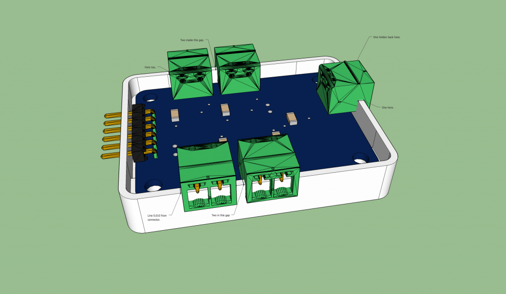
Let’s start with the five Phoenix Contact connectors and the bottom of the enclosure. Hide the top of the enclosure but leave the enclosure bottom and PCB visible. I usually leave a clearance of 0.005″ to 0.010″ around each edge of connector depending on the precision of the printing/machining, machine assembly vs hand assembly, etc. For 3D printed plastic with a hand-assembled PCB, I’m going to use a clearance of 0.010″ on each edge to be on the safe side.
Use the measuring tape tool to put guide points on both the inside edges and outside edges of the enclosure bottom. These guide points should be 0.010″ from the intersection of each connector with the top edge of the enclosure bottom and along the enclosure edge. When you’re done, you’ll have 20 of these guide points. Connect each pair with lines perpendicular to the enclosure edges. Remember to make the lines inside the group with the enclosure bottom. As tedious as this process is, at least we can use the snap to intersection feature of SketchUp versus using a calculator to calculate these points from the connector data sheet and PCB layout.
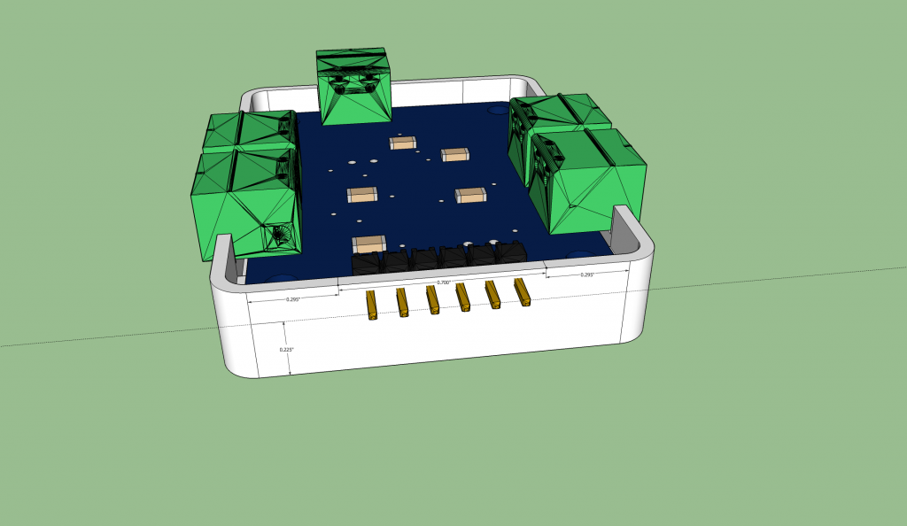
Draw a guide line on all sides about 0.010 below the connectors. I made my guide line 0.225″ from the bottom edge of the enclosure. Use the push/pull tool to lower the side walls to the guide lines underneath each of the five connectors.
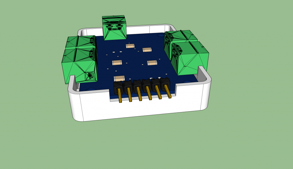
Let’s move to the 6 position, 0.100″ pitch, single row header. I want this cut out to be 0.700″ wide and centered on the header. I also want the bottom of the cut out to be inline with the bottom of the Phoenix Contact connectors. I drew a guide up 0.225″ from the bottom of the enclosure then centered two lines 0.700″ apart on the top edge of the enclosure bottom.
I then used the push/pull tool to lower the side wall to the guide line.
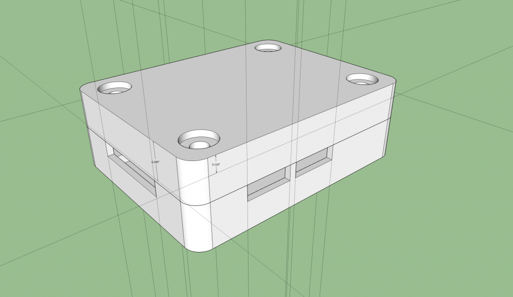
That completes the enclosure bottom. Time to move to the enclosure top. Use the unhide command to unhide the enclosure top. Double click into the enclosure top group and create guide lines at the edge of each lowered wall on the enclosure bottom. We’ll use these guides to transfer the dimensions and cut outs from the bottom of the enclosure to the top of the enclosure. This is probably easiest done with the PCB hidden. Now create a guide line 0.120″ from the top of the enclosure on each side with a Phoenix Contact connector. This will be the height of the cut outs for the Phoenix Contact connectors. On the single row header side, create a guide 0.280 down from the top of the enclosure.
Hide the bottom of the enclosure and orbit the camera to view the top of the enclosure. Use the guides to draw lines across the enclosure edge for each cut out then use the push/pull tool to lower the side walls for each connector.
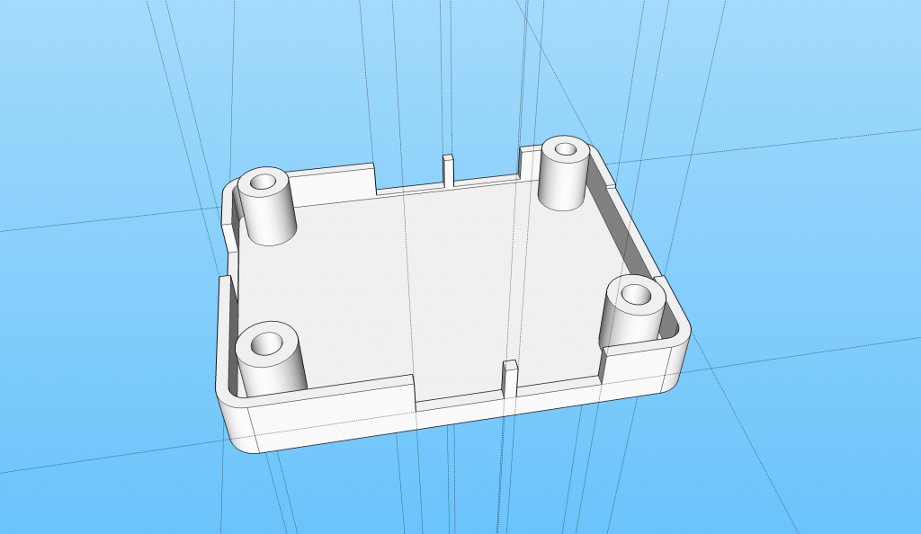
Complete the top cut outs by drawing lines across the edges and using the push/pull tool to lower each side wall.
Delete the guides and unhide the PCB. The enclosure design is done.
Now would be a good time to use the orbit tool to admire your work / check your work for mistakes. Check clearances around the board edges, the top of the board, the bottom of the board, the connectors, where the enclosure top and enclosure bottom meet, etc.
Designing a Mounting Bracket for the Enclosure
I designed a bracket for mounting the enclosure to a flat surface. The bracket has 0.010″ clearances to each edge of the enclosure as well as 0.010″ clearance to the top and bottom surfaces of the enclosure. All bracket walls are 0.100″ thick. Across the four legs on the bottom are DIN74A countersinks for M3 screw heads.
The bracket works by bolting it to a flat surface then snapping the enclosure into the bracket.
The bracket design is a bit more complicated than the enclosure design but the techniques outlined in this tutorial still apply. The important parts to remember are the clearances and wall thicknesses. Again all walls are 0.100″ and the clearance from any surface of the bracket to any surface of the enclosure is 0.010″. The inside corner radius is 0.150″ and the outside corner radius is 0.225″.
Exporting the STL
To 3D print the model, you will need an STL file. To generate the STL file, you’ll need the Export STL plugin for SketchUp. Once the plugin is installed, you’ll need to export the different pieces of the enclosure in separate files. Open the SketchUp file for the enclosure. Select the top half of the enclosure then select Export STL… from the File menu.
Make sure “Export Selected Geometry Only” is checked, export unit is “Model Units,” and File Format is “ASCII.” Click “Export” and save the exported STL with a recognizable filename and in a convenient location.
Repeat the above process except this time select only the bottom half of the enclosure. If you designed a mounting bracket or want to print the mounting bracket from the tutorial example files, select the mounting bracket and repeat the process a third time.
Once the three files are exported, move on to the next step to check the manufacturability of your design.
Checking the STL for Errors
Netfabb Basic is a free version of Netfabb. Netfabb is a tool for checking the manufacturability of STL designs using the 3D additive printing processes. Download, install, and register the tool. Once it’s setup, launch the tool.
For each STL file to be printed, repeat the following process:
- Select Project -> Add Part.
- Select the STL file using the open file dialog box.
- If you don’t see a large exclamation mark inside a triangle in the lower right hand corner of the screen next to your part, your part is ready to go.
- If you do see a large exclamation mark, you’ll need to run the design analysis tools to find out what is wrong.
- Repeat the above process for each STL file.
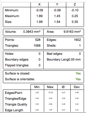
To run a design analysis, select Extras -> New Analysis -> Standard Analysis. The analysis will run and a box in the lower right hand corner of the screen will list some information about your design.
For your part to be manufacturable, the number of shells needs to be equal to 1 (assuming you only have one part in the STL file), the surface must be closed, and there should be no flipped triangles.
If there’s a problem with your design, you can let Netfabb Basic attempt to repair your STL file automatically or you can fix the design in SketchUp, re-export the STL, and check the STL file again.
Generally speaking, one of three things happens to make your design fail manufacturability checks:
- Reversed faces. The back sides of the faces in SketchUp are drawn in a purplish color. Any exposed purple face is a reversed face. To fix reversed faces in SketchUp, select any faces that appear purplish and select Edit -> Face -> Reverse Faces. The faces should appear grayish now.
- Missing external wall. Missing external walls can be found by orbiting the module and looking for holes in the external surface. To fix a missing external walls, use the line tool to draw a line from one existing point to another existing point along the surface where the face should be. SketchUp will draw the missing face as soon as the line is completed.
- Internal walls. Internal walls are the most difficult problems to locate because they are internal to the model and are completely hidden by the model’s exterior walls. They can be found using a combination of the SketchUp Section Plane tool and by viewing the model using the X-ray style (View -> Face Style -> X-ray). Generally speaking, you’re looking for any faces that are internal to the model. These faces need to be deleted once they’re found.
For more details on repairing a model, Shapeways has a great tutorial on using Netfabb Basic to repair a part’s geometry.
Ordering the Enclosure Parts
Once the parts are fixed, it’s time to 3D print them either using your own printer or using a service bureau. Since I don’t own a 3D printer (yet), I have to use a service bureau to print my models. The two services that I have used are Shapeways and Sculpteo. They both print models out of PA2200 nylon using a selective laser sintering process (SLS) on EOS Formiga P110 printers. They both are relatively affordable and offer a variety of colors and finishes for your designs. Sculpteo tends to be a little faster (3 days for basic white) than Shapeways (up to 10 days for basic white).
Sculpteo offers the option of printing in colored plastic without surface polishing. When printing in color with Shapeways, the surfaces are always polished. Polishing can knock down fine edges on a model. For example, the small thin walls between the two Phoenix Contact connectors in this design run the risk of being broken during the polishing process. Also the enclosure walls may be a bit thinner at the top than they are at the bottom after polishing.
I’d recommend creating an account on both services, uploading the STL for the designs to both services, then experimenting with different materials and finishes on each to find the optimum combination of material, color, shipping times, and cost.
Be sure the model units and dimensions on the printing service match the units and dimensions in SketchUp! Uploading a file exported in inches and selecting millimeters at the service bureau can result in a much smaller 3D print than expected! Sculpteo has an option to download a blueprint of the model with the dimensions called out. I recommend taking advantage of this to verify the dimensions of your model before printing.
At Shapeways, I’ve successfully printed these models out of their Strong & Flexible Plastic and their Polished Strong & Flexible Plastic materials. When using the polished material, you may need to submit designs with thin / small pieces with the ”Print it anyways!” option. This will cause them to skip their manufacturability checks and print your model regardless of any design rule violations.
At Sculpteo, I’ve successfully printed these models out of white plastic and colored plastic. I have not used the polished plastic option.
The Results
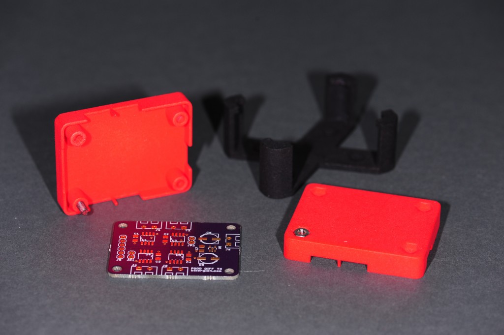
I’m happy with the results of designing and printing this enclosure. Below are some photographs of the enclosure in both white and red plastic with the mounting bracket printed in black plastic.
Resources
These designs are part of the my led-pixels BeagleBone Black project. I’ve uploaded the SketchUp and STL files for this tutorial to my Github repository for this project. Note that the tutorial files were purpose built for the tutorial after printing my design. As such, I’ve not actually printed these files. Use them at your own risk. The enclosure tutorial files are located inside the mechanical/enclosure-tutorial folder of this project repository directory on github. I’ve also uploaded the exact files used to order the 3D prints of the enclosure shown in the photos to the mechanical/enclosure-as-built folder of the same repository.

