
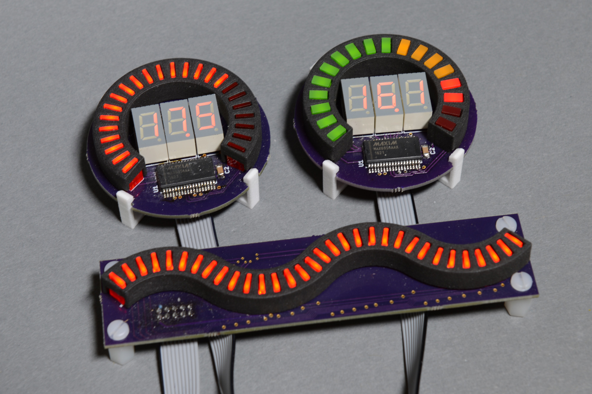
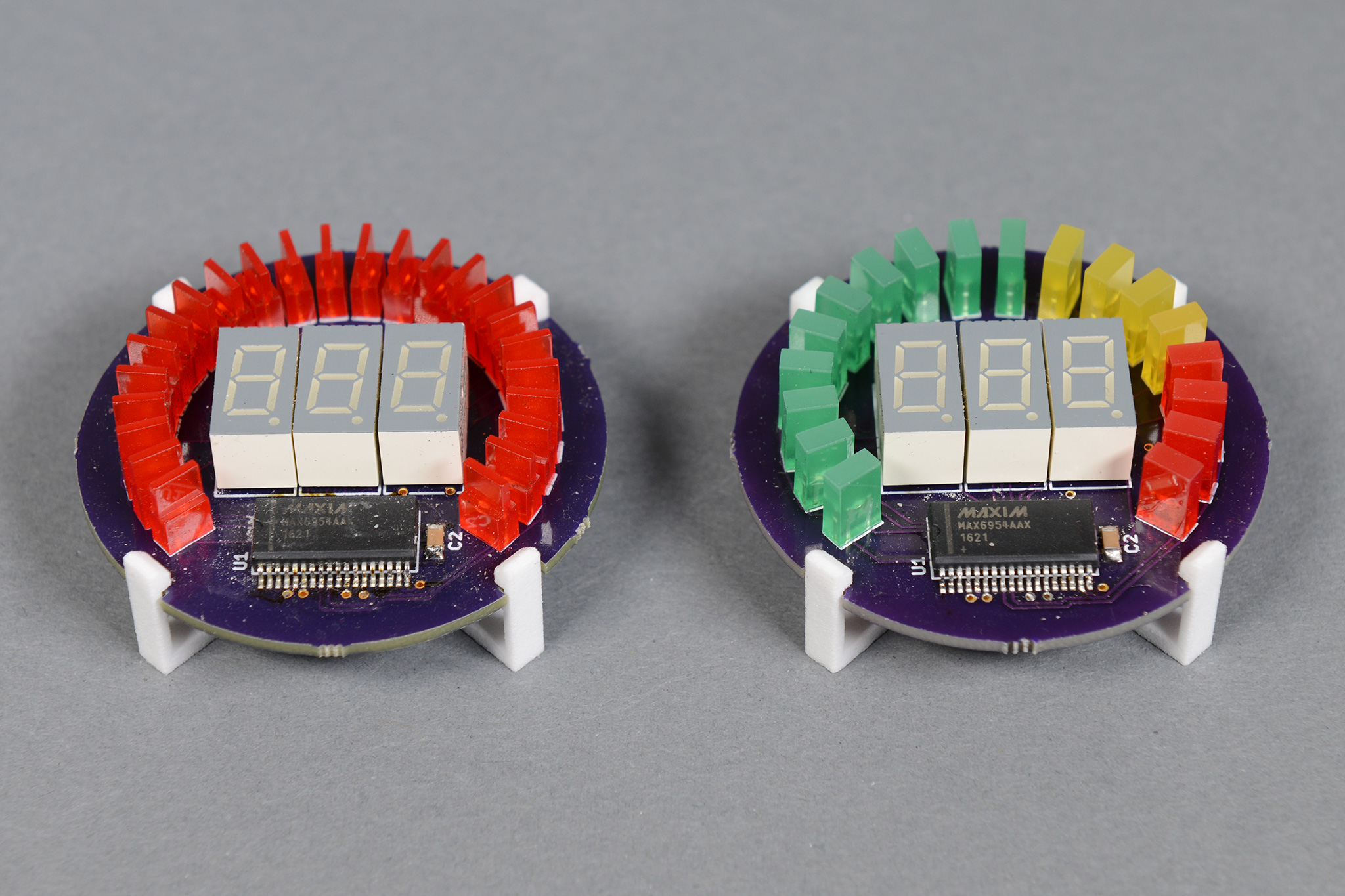
Three different bar graphs built using Matlab, Eagle, Fusion 360, and 3D printing.
While building my zombie containment unit, I decided I wanted some LED displays or bar graphs to complement the containment status video running on the smaller secondary video monitor. Some other containment units used LED air pressure gauges from eBay. I wanted to achieve a similar look, but I also wanted my gauge to be software controllable so I could change the number of segments lit in response to events in the playback of the two videos. I decided it was time to build my own LED bar graphs.
My initial thought was to buy some pre-made curved bar graph segments and build my own board to hold them. Unfortunately, no distributors stocked these bar graphs and I didn’t want to purchase the minimum order quantity of 500.
I decided to build a board to hold a bunch of discrete LEDs arranged in a circle and at the correct angles. Soldering them by hand and keeping everything perfectly aligned, however, was going to be problem. I also did not want light from the lit LEDs to bleed into the unlit LEDs. Fortunately 3D printing could solve both of these problems: a 3D printed holder could hold the LEDs while soldering them and act as a separator to prevent light bleed.
Picking LEDs and a Driver IC
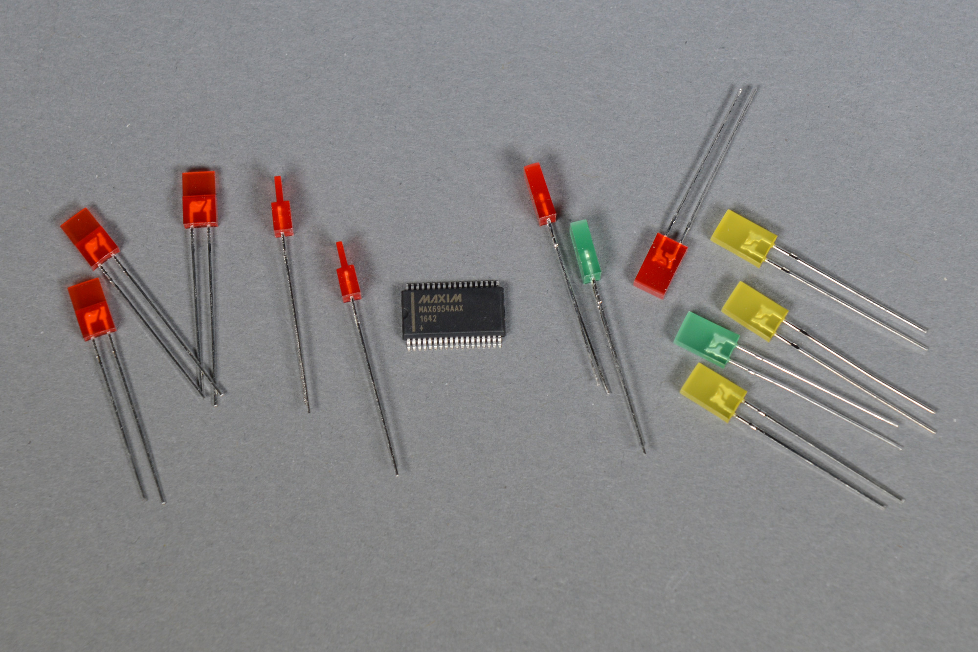
1 x 5 mm LEDs, MAX6954 driver IC, and 2.5 x 5 mm LEDs.
The first step is to pick some LEDs and a driver IC to drive them. I searched Kingbright’s website and settled on two possible LED candidates in three different colors.
The first LED was a 1 x 5 mm rectangular LED with a 2.8 x 5 mm base. I settled on the 625nm red version of this LED, part number WP1053IDT. Finding this LED in stock in green and yellow proved to problematic but I still wanted to do a display that used red, yellow, and green LEDs so I decided to build a second display with another LED too.
The second LED was a 2.5 x 5 mm rectangular LED. This LED’s dimensions are constant throughout its height. This LED was stocked in red (WP513IDT), yellow (WP513YDT), and green (WP513GDT) by a distributor too.
After searching for quite some time for a suitable driver IC, I finally settled on a Maxim MAX6954 common cathode LED display driver in a 36-pin SSOP package. This driver IC can drive up to 128 discrete LEDs, sixteen 7-segment dispays, eight alphanumeric displays, or some combination in between. It requires very little external circuitry and has a simple SPI interface for controlling the attached LEDs. Then I looked at the cost—about $20 each in single quantities. Ouch! But board space was at a premium and I wanted to add a few 7-segment displays to the graphs too so this IC was the perfect fit for the job.
Trigonometry Time
After picking out the basic components, the next step is to decide on a board size, the number of LEDs on the board, and the radius and length of the arc that encompasses the LEDs. The 3D printing process imposes a constraint on these decisions: the minimum wall thickness in the selected 3D printing process is about 1.5 to 2mm so the LEDs can be no closer to each other at their closest points than about 1.5mm.
I settled on a 50.8mm (2”) diameter board with the LEDs arranged in a 270 degree arc with a radius of 18.5mm. For the smaller 1 x 5mm LEDs, I placed 24 LEDs on this arc and for the larger 2.5 x 5mm LEDs, I placed 18 LEDs on this arc.
For the first three LEDs on the first board, I did the calculations by hand then moved and rotated the LEDs using the Eagle PCB command line. This quickly became monotonous and error prone.
Matlab to the Rescue
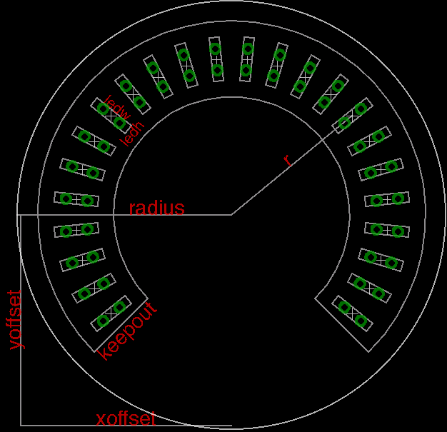
Variables used by the Matlab script and their relationship to the final board layout.
To simplify these calculations, I wrote a Matlab script. When executed, the Matlab script sets a bunch of variables that control the spacing and position of the LEDs on the bar graph board, calculates the position and rotation of each LED, then generates an Eagle PCB script that will place the LEDs, draw a board outline, and draw some informational lines that show where each LED and the 3D printed LED holder will be located on the board.
The variables are as follows (see the diagram above for their relationship to the completed board):
- nLedPos: the number of LEDs in a complete circle.
- nLeds: the number of LEDs used on the bar graph.
- r: the radius of the arc containing the LEDs in millimeters.
- xOffset and yOffset: the x and y offsets to the center of the board in millimeters. It’d be nice to keep the bar graph centered at the origin but my Eagle PCB license will only permit components to be placed in a small area northeast of the origin.
- keepout: the width of the region occupied by the 3D printed holder in millimeters. This is measured normal to the arc containing the LEDs. For example with r = 18.5mm, a keep out region will be created between arcs at a radius of 14mm and a radius of 23mm.
- radius: radius of the board for the board outline layer.
- ledw and ledh: the width and height of the LED plus any margin for the hole in the 3D printed holder.
With the Matlab script and generated Eagle PCB script, it’s pretty quick and easy to iterate through multiple designs in Eagle PCB and see how the LEDs will be spaced and placed on the board.
Designing the Board
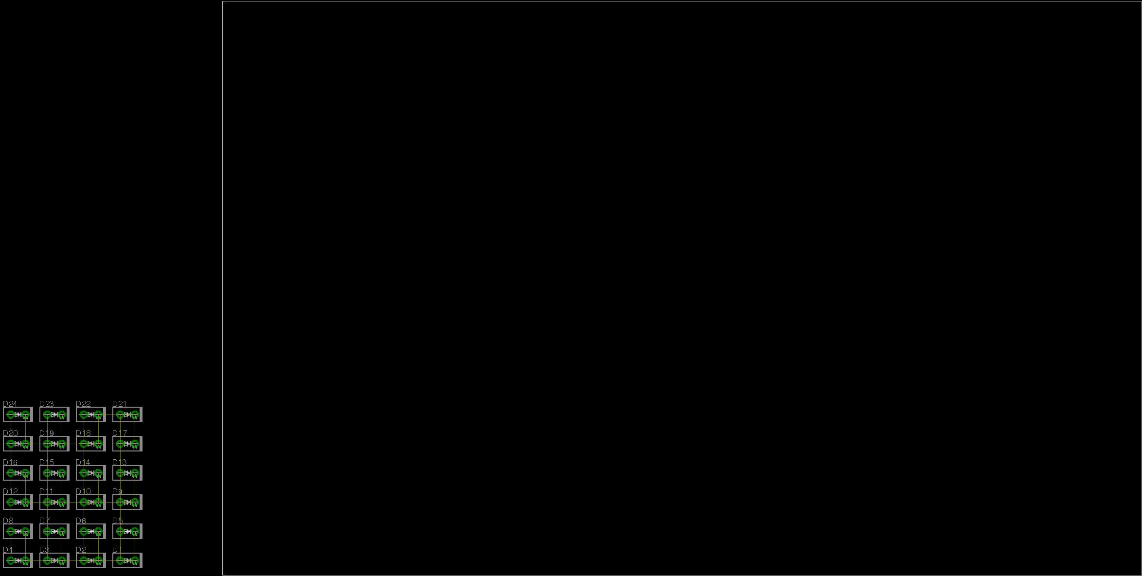
With all the design decisions completed, it‘s time to run the Matlab script and note the location of the generated Eagle PCB script. Open Eagle PCB and generate a schematic containing the number of required LEDs. These should be labeled D1 … Dn where n is the number of LEDs (nLeds) from the Matlab script. See the figure below as an example.

Schematic with just the LEDs.
Select switch to board to generate a board from the schematic. It’ll look something like the picture below.
Default layout after generating the board from the schematic.
Delete the default board outline from the dimension layer then run the generated Eagle PCB script using the File…Execute Script… menu option in the PCB layout tool. The board should now look something like this with all the LEDs, board outline, and dimensions placed:
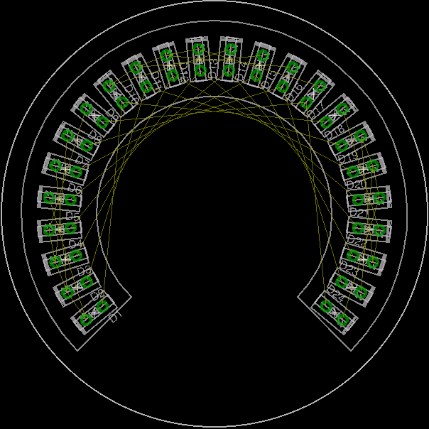
Board after LEDs, dimensions, and keep outs have been placed by the generated Eagle PCB script.
At this point, if you don’t like the placement of the LEDs, change the parameters in Matlab and repeat the process.
The final step is to add the rest of the components required by the design to the schematic and finish the board layout. Here’s my final schematic:
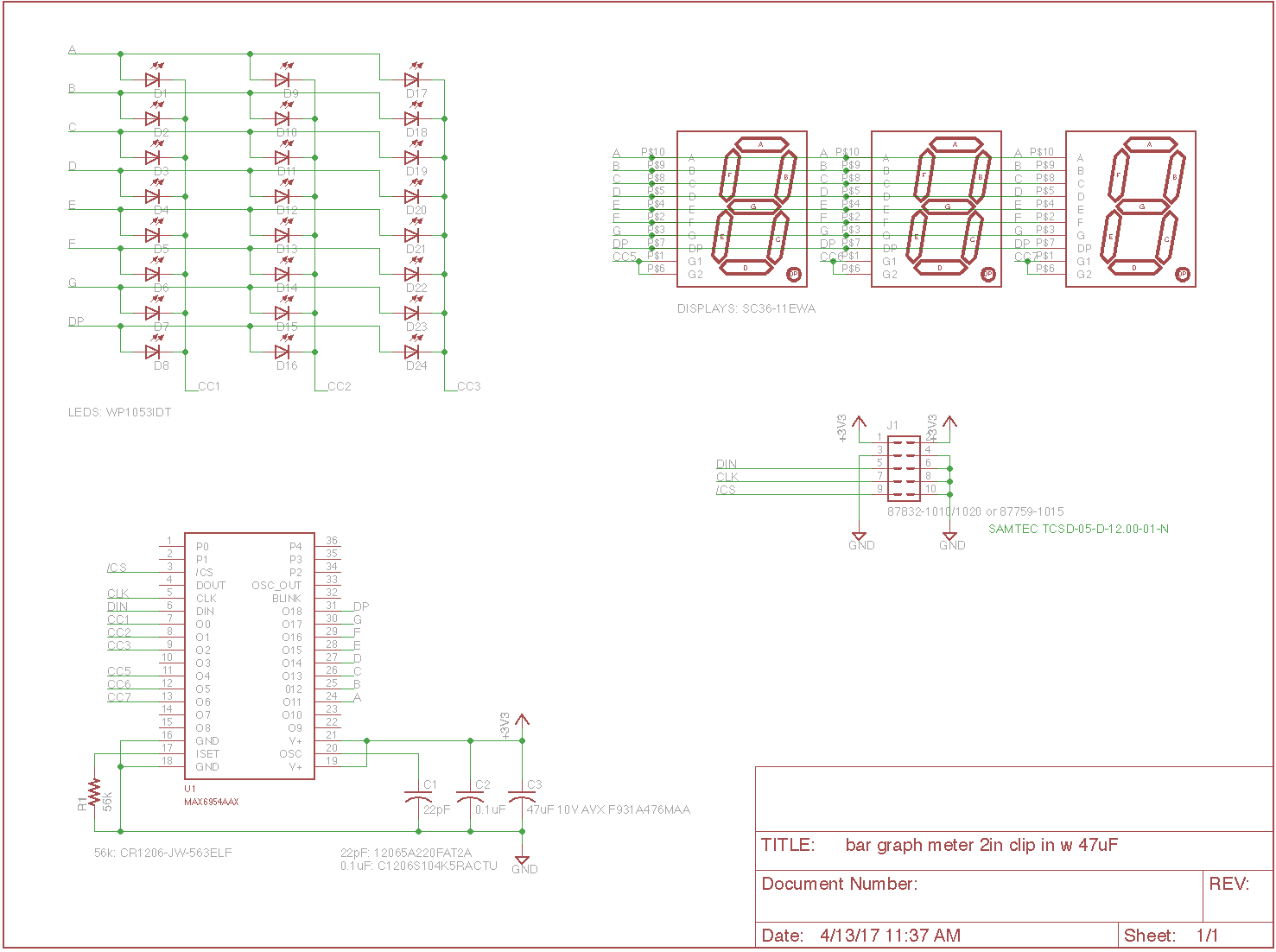
Final schematic.
And my final board layout:
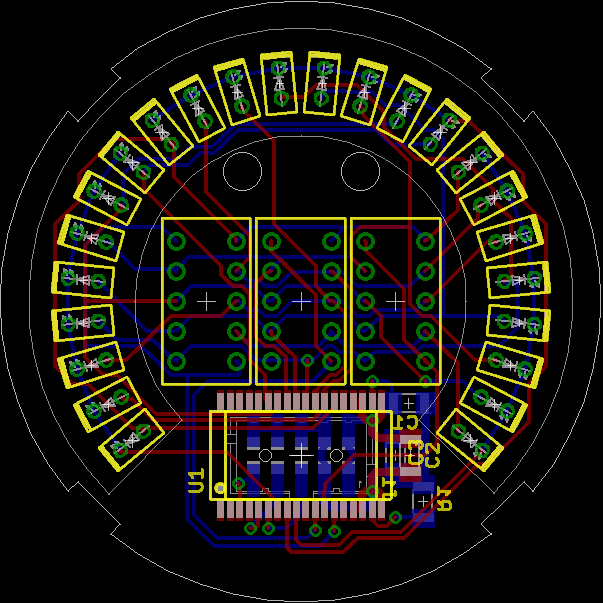
Final board layout.
And the boards fabbed from the above files:
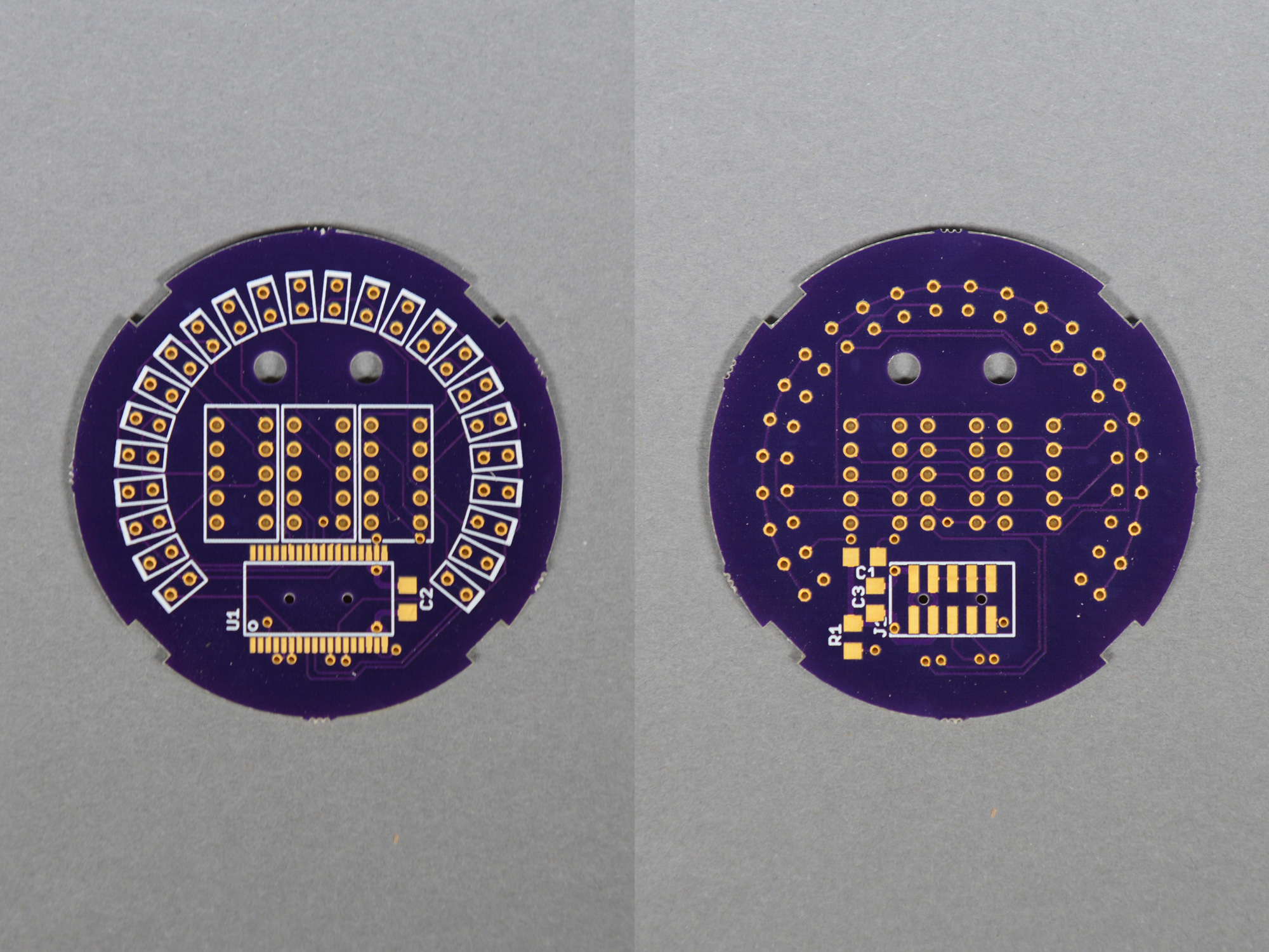
The fabbed board for a 270 degree arc with 24 1 x 5mm LEDs.
I added some notches to the board outline to allow the boards to snap into a holder for either surface or panel mounting the finished displays:

Board placed into a 3D printed plastic snap-in bracket for surface mounting.
Designing the LED Holder
I used Autodesk Fusion 360 to design the LED holder. The first step in creating the holder is to create a sketch matching the dimensions of the LED holder keep out area from the PCB board and with a hole for a single LED. We’ll duplicate the LED hole to all the required positions after extruding the sketch into a 3D body.
Some reminders of the required dimensions:
- The radii of the keep out area are 18.5mm ± (9mm/2) = 14mm and 23mm. These arcs extend 270 degrees from -45° to 225°.
- The center of one of the LEDs (D20) is at r = 18.5mm and θ = (360/32/2) = 5.625°.
- From printing a rectangular piece with different sizes of LED holes, I learned the LED hole needs to be 0.2mm larger than the LED so for a 1 x 5mm LED, the hole needs to be 1.2 x 5.2mm.
To create the sketch:
- As always in Fusion 360, first things first: create a new component to hold your design.
- Create a new sketch.
- Create two circles centered at the origin, one with a radius of 14mm and the second with a radius of 23mm.
- Create two lines radiating outward from the origin to the edge of the outermost circle. One line should be at an angle of 225°; the second at an angle of -45°. Both lines should have a length of 23mm.
It should look something like this now:
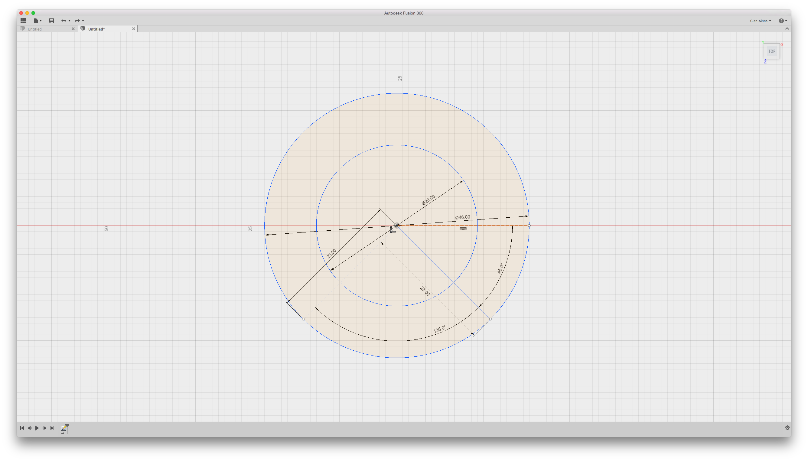
Circles and lines complete.
- Now use the trim tool to delete the unneeded lines.
It’ll look something like this now:
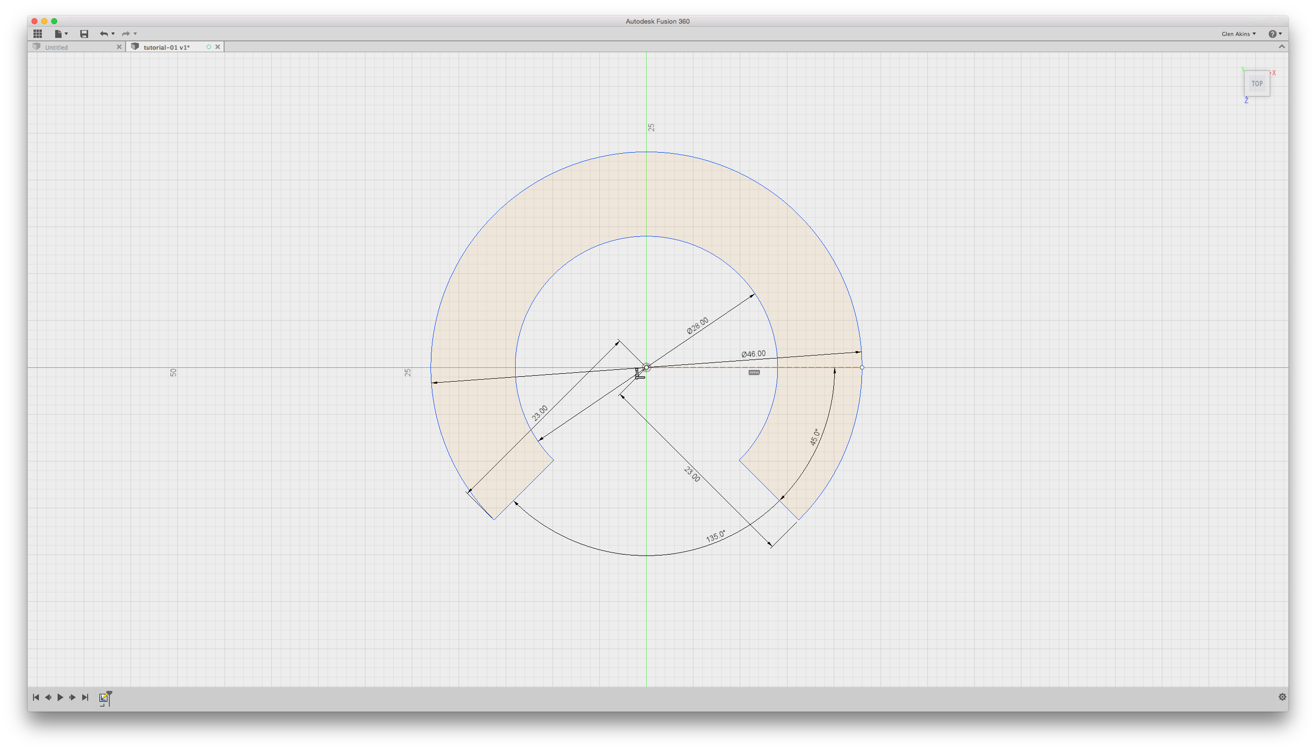
Trim complete.
Now add the hole for the LED:
- Create a line from the origin with a length of 18.5mm and an angle of 5.625°.
- Create a 3 point rectangle. The first point is at the end of the line drawn in the previous step. The second point is 2.6mm (1/2 of 5.2mm) back along the same line. The third point is up 0.6mm (1/2 of 1.2mm) from the same line.
- Create two more 3 point rectangles so that you end up with a final rectangle that is 1.2 x 5.2mm. It’ll be divided up into four regions.
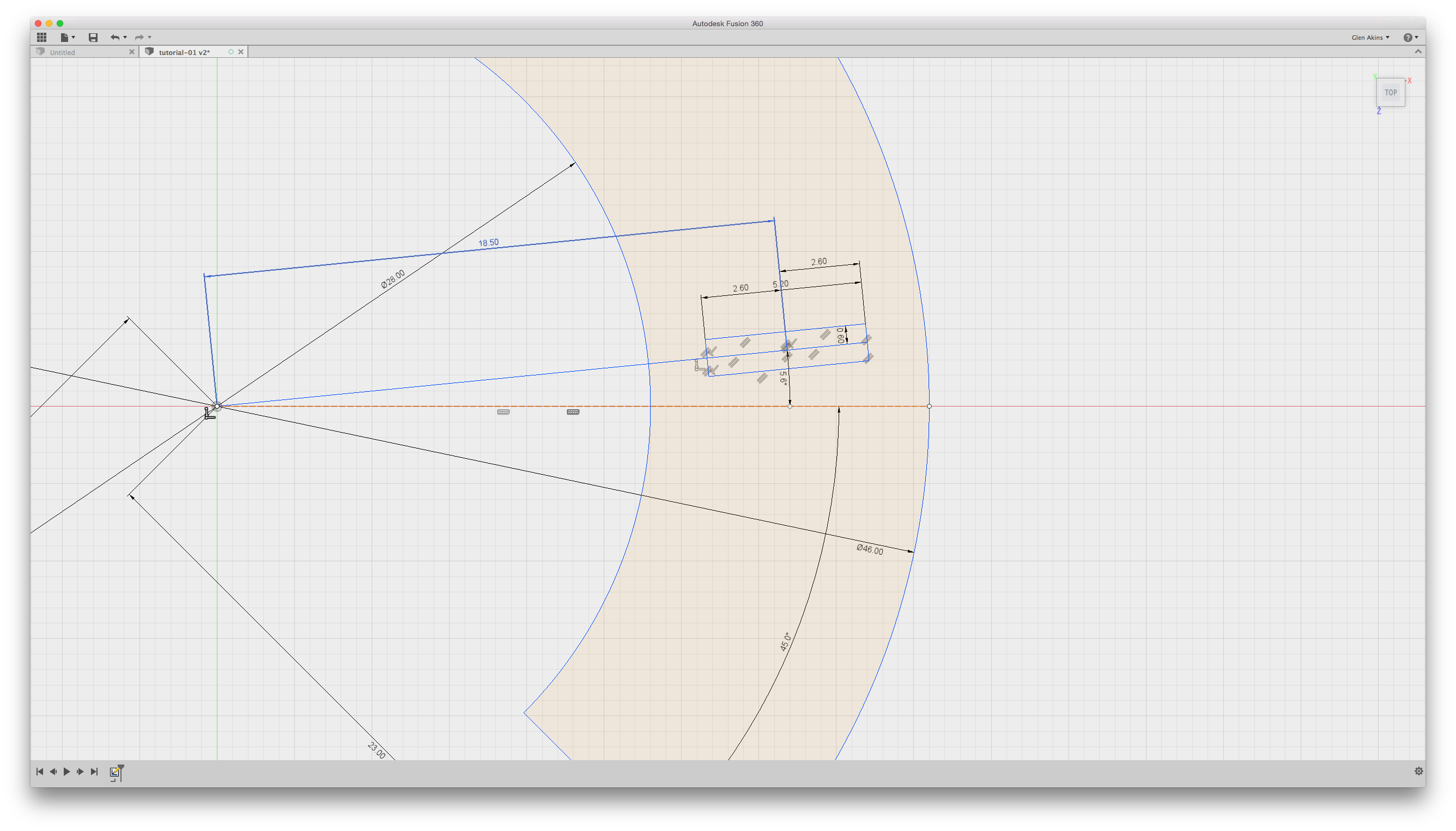
Location of rectangular cut out for one LED.
- Now use the trim tool to get rid of the excess lines leaving just a single rectangle for the LED hole.

Finished sketch.
Now create the 3D body and the required LED holes:
- Exit the sketch and use the press pull tool to extrude the sketch up 3.5mm. This is the height of the portion of the led that is 1 x 5mm (4mm) minus 0.5mm.
- Select the four faces of the LED hole.
- Select Pattern…Circular Pattern from the Create menu.
- Click Axis in the popup dialog box and select the Y axis to rotate the pattern about the Y axis.
- For quantity, enter 32.
- Uncheck the holes outside the body of the LED holder.
- Click OK.
Creating the circular pattern.
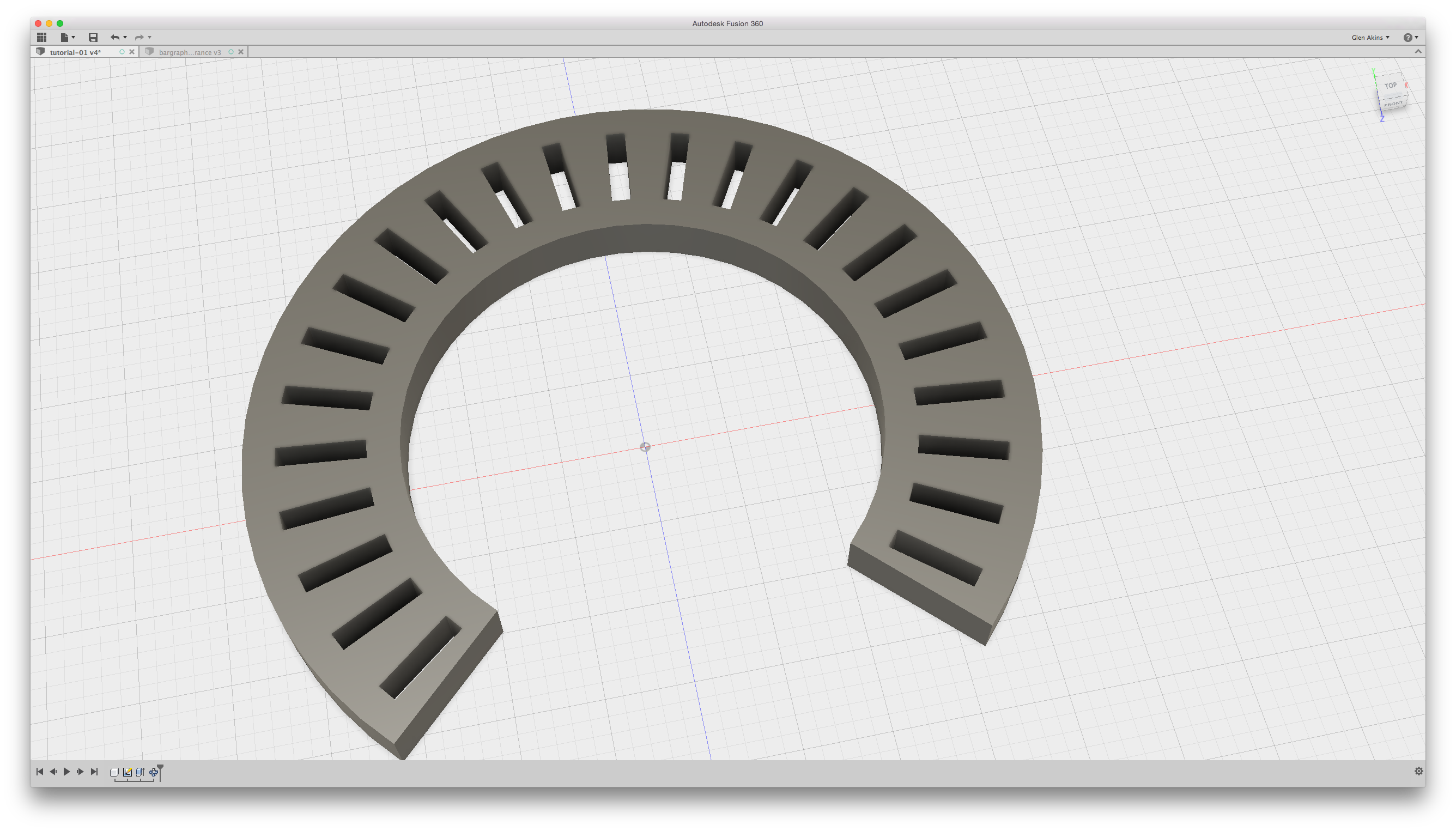
Circular pattern complete.
Next I created a shroud on the bottom of the LED holder to mask light escaping from the bottom. This shroud is 4mm tall and 1.5mm thick on both the inside out side radius of the LED holder.
- Select the bottom of the LED holder and select create a new sketch.
- Create two center point arcs located at the origin with a radius of 15.5 and 21.5mm on the bottom face of the LED holder.
- Stop the sketch.
- Select the two faces between the arcs and the outside edges of the LED holder.
- Use the push pull tool to extrude these two faces down 4mm.
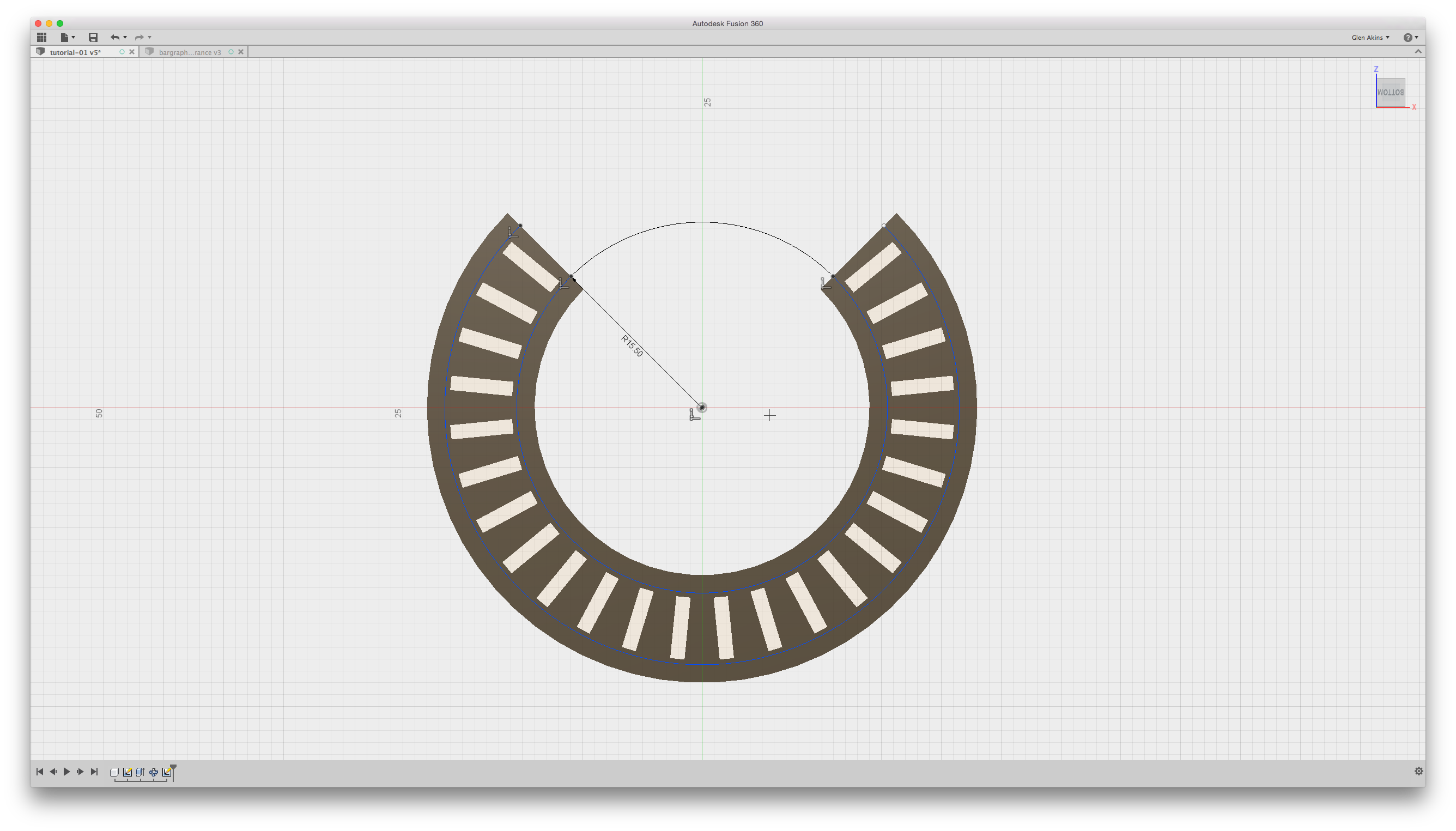
Arcs on bottom of LED holder.

LED holder with shroud extruded.
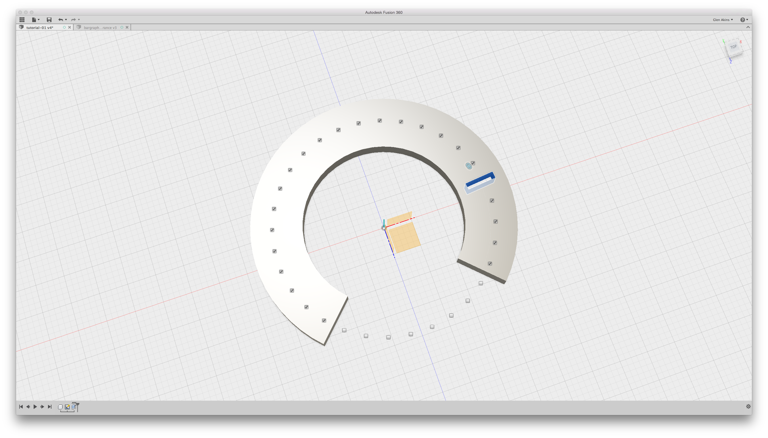
At this point the LED holder is complete. Since I opted to mount my board using a board holder with snap-in tabs, I creating a cutting tool out of the tabs on the board holder and used the cutting tool to remove any plastic on the LED holder that might interfere with the snap-in tabs. My finished LED holder looked like this on the bottom:
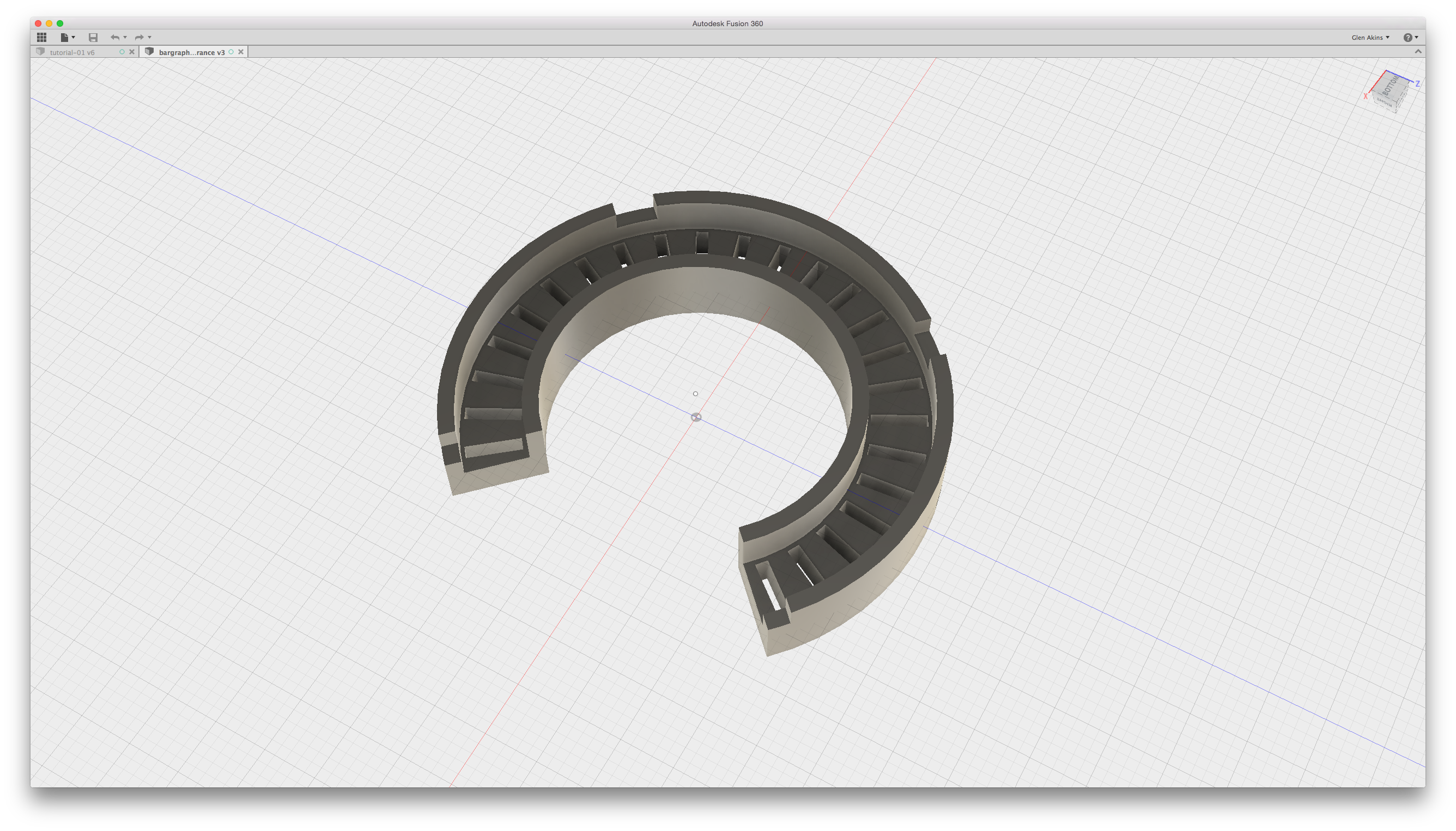
LED holder with plastic removed to prevent interference with snap-in board holder.
Verifying the Fit
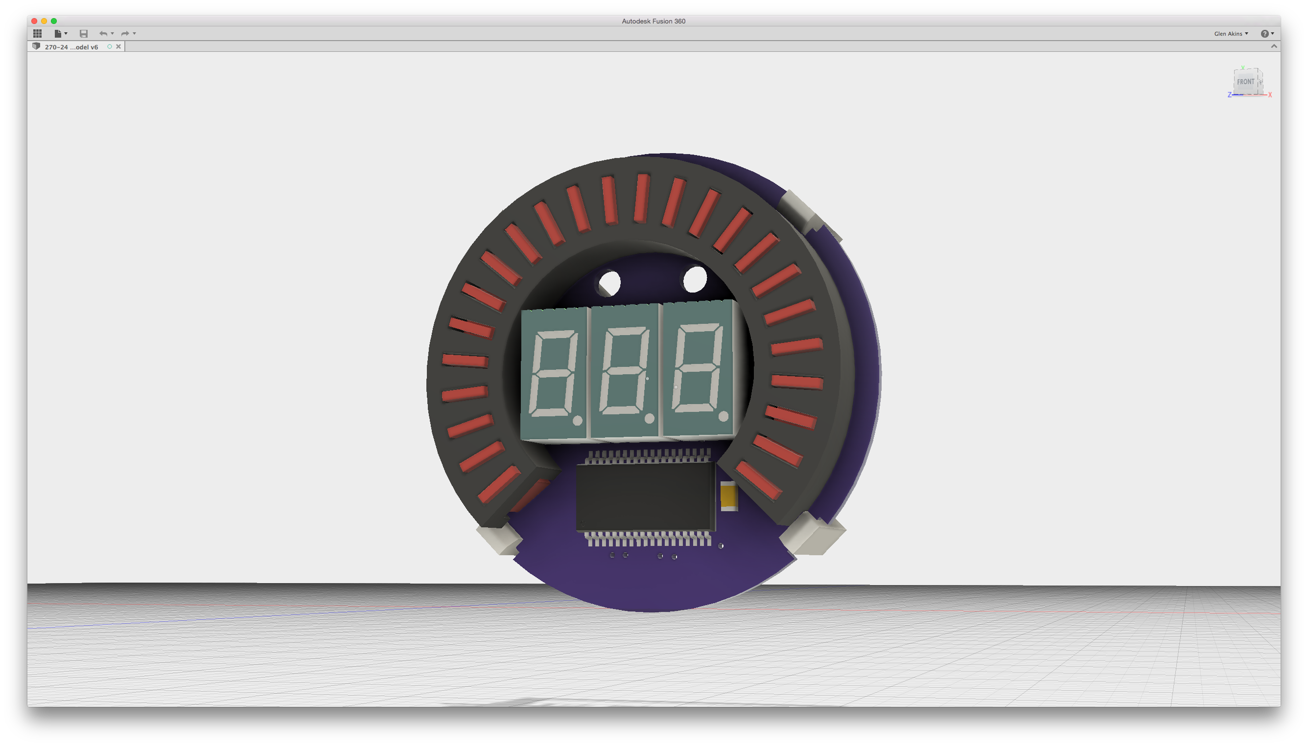
Verifying the fit of the circuit board, board holder, and LED holder in Fusion 360.
The final step before manufacturing the LED holder is to make sure the LED holder and the LEDs on the circuit board will fit together properly. To do this, I used ecad.io. After logging into the website, I uploaded my Eagle PCB board file and 3D models of the LEDs and other components obtained from the component manufacturers’ websites. Once everything was placed in ecad.io, I created a STEP AP214 Part File containing a 3D mechanical model of the board and components. Once the file was created, I downloaded the resulting .step file to my computer.
Back in Fusion 360, I uploaded the .step file and added the LED holder and board holder components to the model. I visually checked for interference but I could have also used the Inspect…Interference command in Fusion 360. Once I was satisfied with the fit, I selected the LED holder component and selected Make…3D Print. I set mesh refinement to fine and opted to save the .stl file to my computer rather than use the 3D Print Utility. Finally, I uploaded the .stl files to a 3D printing service and printed the models.
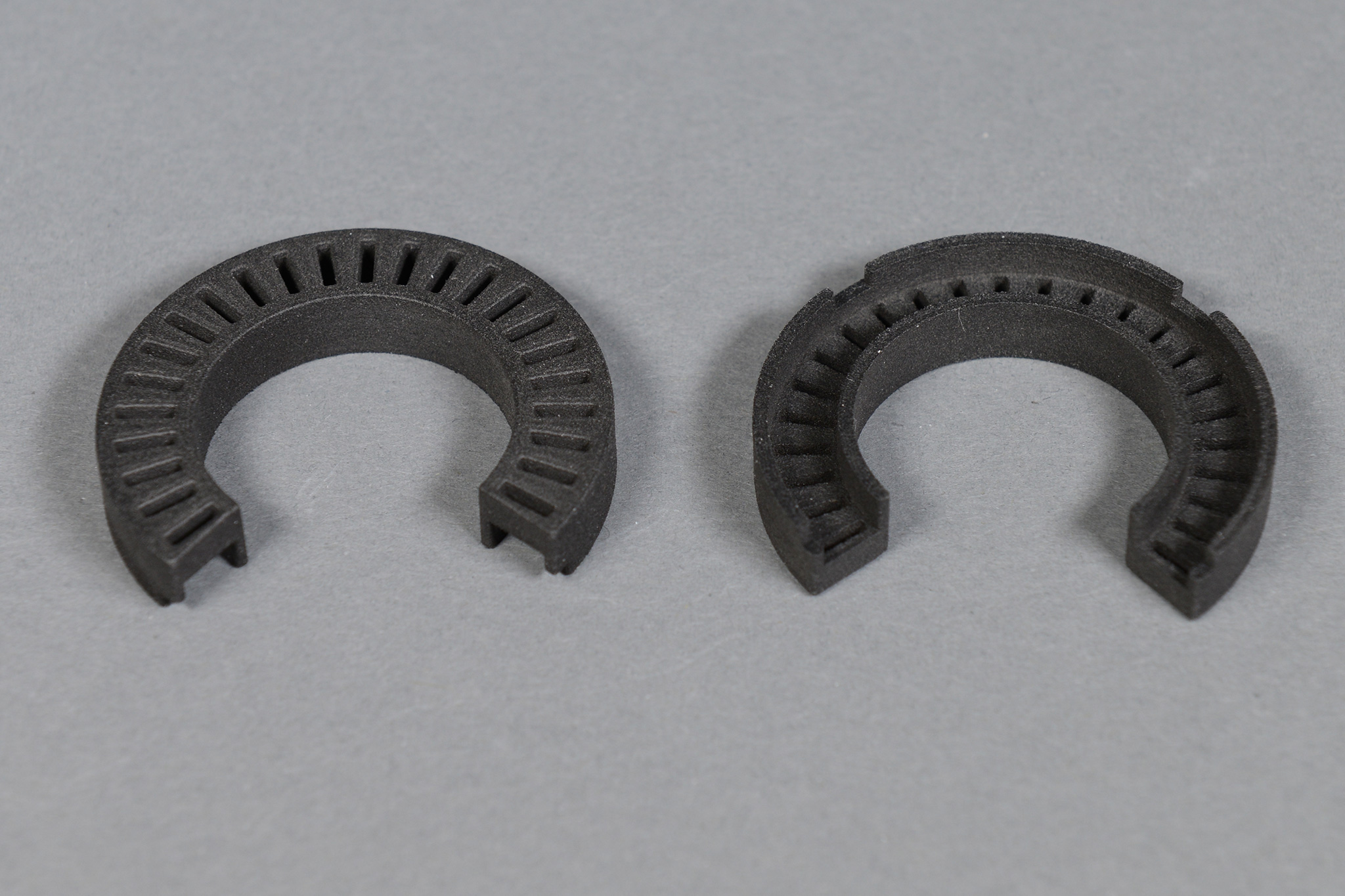
Finished 3D printed LED holders for the 24 LED bar graph.
Final Assembly
To assemble the bar graphs, I soldered all the surface mount components to the board. After these were done, I stuffed the LEDs into their pads and placed the 3D printed LED holder over the LEDs. I then very carefully soldered the LEDs in place. After soldering all the LEDs, I removed the LED holder to see how they looked:
No way the soldering job would be this neat without the use of a 3D printed part to hold the LEDs in place during assembly.
Here’s the assembled LED bar graph with the LED holder and board holder in place:

Assembled LED bar graph.
More Ideas and Options
In addition to the surface mount snap-in mounting bracket, I made a panel mount for the LED bar graphs:
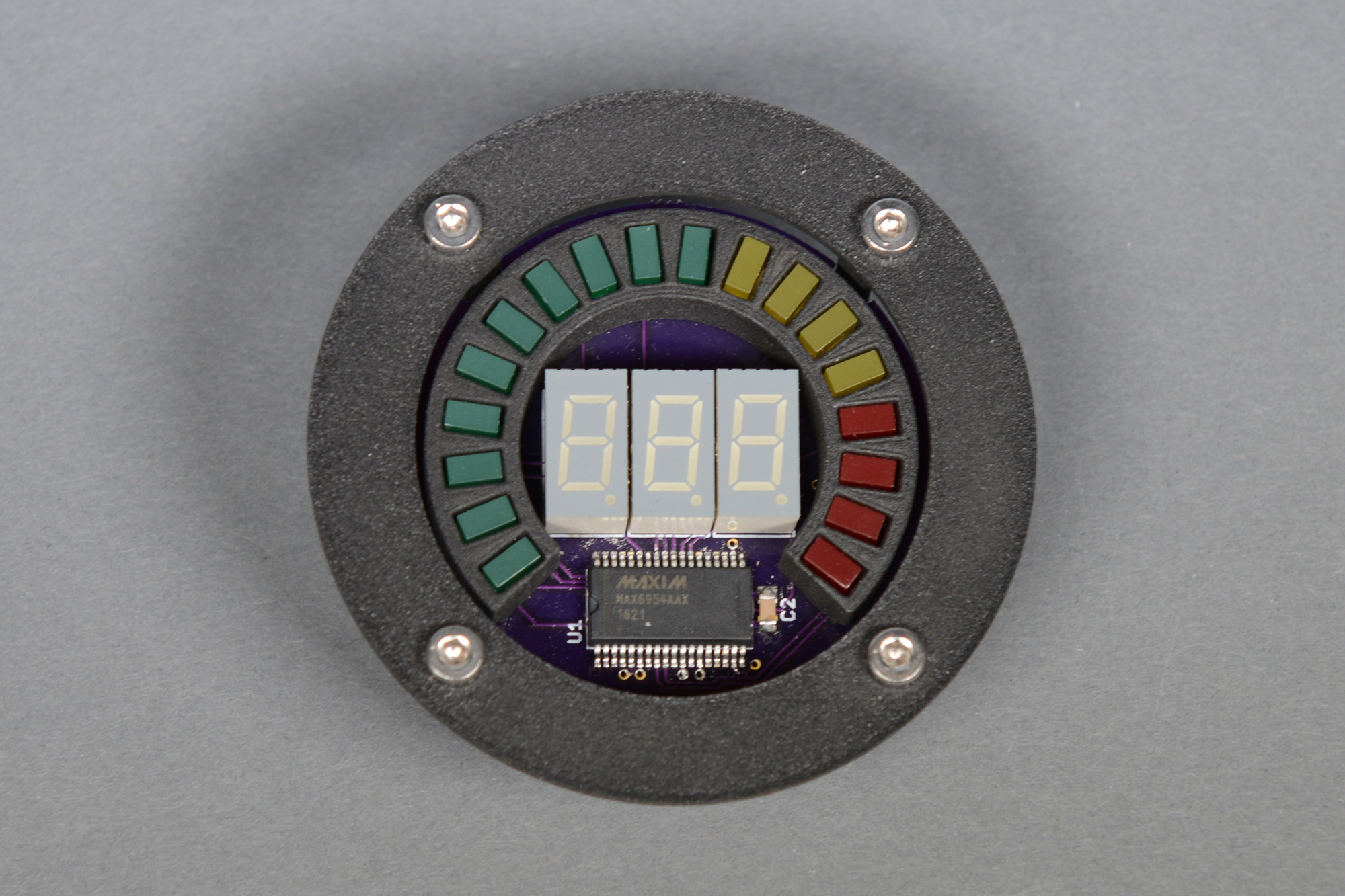
Panel mount. With a circular diffused gray translucent acrylic cover, this would look even better.
One of the coolest things about 3D printing your own bar graphs is that you’re no longer limited to mass produced bar graph displays in stock shapes. You can make your own displays in any shape you want. For my zombie containment unit, I made one circular red display and a 2nd display in the shape of a squiggle. I mounted both of these to an aluminum panel and stuck it to the front of the prop:

A circular bar graph and a randomly shaped bar graph on my zombie containment unit Halloween prop.