
In this post, we’ll add motion to the googly eyes using a microcontroller and some stepper motor drivers.
In part 1 of this series of posts, we built a giant set of robotic googly eyes. Now it’s time to animate them! To keep the project simple, we’ll use an Arduino Uno and a pair of Big Easy Driver stepper motor drivers. Let’s get started.
Required Parts
To animate the eyes, you’ll need the following parts:
- 1 Arduino Uno, $20
- 2 Big Easy Drivers, $20 each
- 10 3.5mm Pitch, 2-Pin Screw Terminals, $0.95 each
- 1 DC Power Supply for the Motors, 12-24V, 1A, $20
Total cost for these parts is about $90 excluding shipping and handling.
Prepare the Motor Drivers
The first step is to prepare the stepper motor drivers.
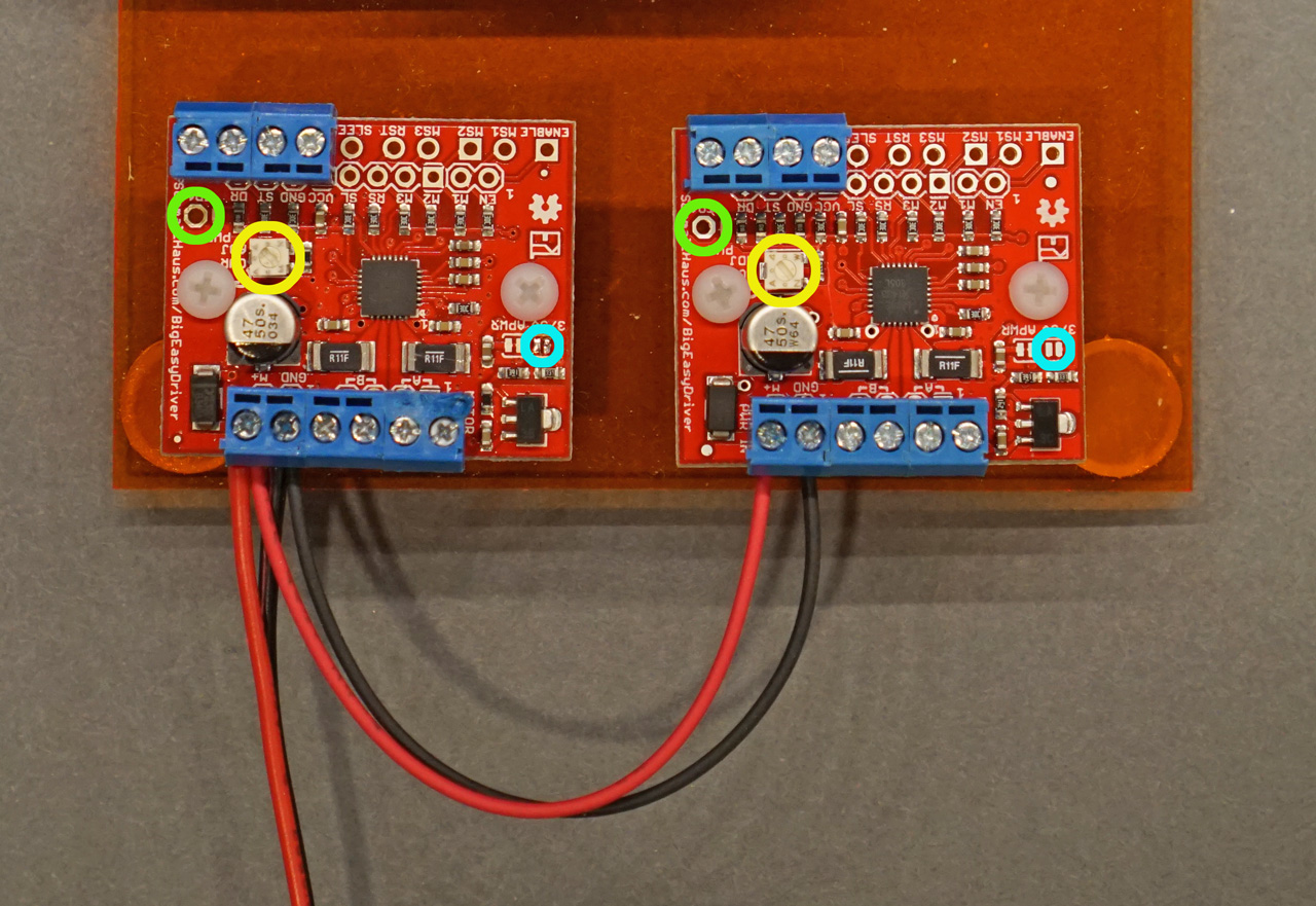
Big easy driver power connections, +3.3/5V selection pads (blue), Vref test point (green), and current setting pot (yellow).
Refer to the photo above as you complete the following steps:
- Connect the M+ screw terminals on both drivers to the (+) lead of the 24V motor power supply and the GND screw terminals immediately next to the M+ terminals to the (-) lead of the 24V power supply as shown in the above photo. Do NOT connect the 24V motor power supply to the Arduino! Doing so will likely damage the Arduino.
- Verify the +3.3/5V selection pads are not shorted or soldered together. These are highlighted above in light blue. If the pads are bridged together, use a soldering iron and some solder wick to clear the solder between them.
- Calculate the reference voltage for the motor drivers. The reference voltage sets the current through the motor windings. Our motors have a rating of 0.5A. The reference voltage to set the current to 0.5A is computed as follows:
Vref = I*(8*Rref) where I = 0.5A and Rref = 0.11Ω.
Vref = 0.5*8.0*0.11 = 0.44VIf you used different motors than I specified in part 1, be sure to use the current rating of your motors rather than 0.5A.
- Next use a voltmeter and a small screwdriver to set the calculated reference voltage.
- Connect the ground lead of the voltmeter to a convenient ground point in the circuit.
- Place the positive lead of the voltmeter on the test point highlighted above in green.
- Plug in and turn on the motor power supply.
- Slowly adjust the current setting knob highlighted above in yellow until the voltage at the test point is just under the calculated reference voltage (0.44 volts).
- Repeat this procedure for the 2nd stepper motor driver.
- Turn off and unplug the motor power supply before moving to the next section.
My motors ran pretty hot (140°F) using the specified maximum current and calculated reference voltage. To make the motors run cooler, I adjusted the reference voltage down to half the calculated value and used 0.22 volts instead of 0.44 volts. The motors still had plenty of torque and ran significantly cooler (100°F).
Connect the Stepper Drivers to the Arduino and Motors
The next step is to connect the Arduino to the stepper drivers and the stepper drivers to the stepper motors. Below is a diagram of the connections between the stepper drivers, the Arduino, and the stepper motors. Below that are two checklists listing the signal names and their connections. Use the diagram and the checklists to connect the Arduino to the stepper drivers and then the stepper drivers to the stepper motors.
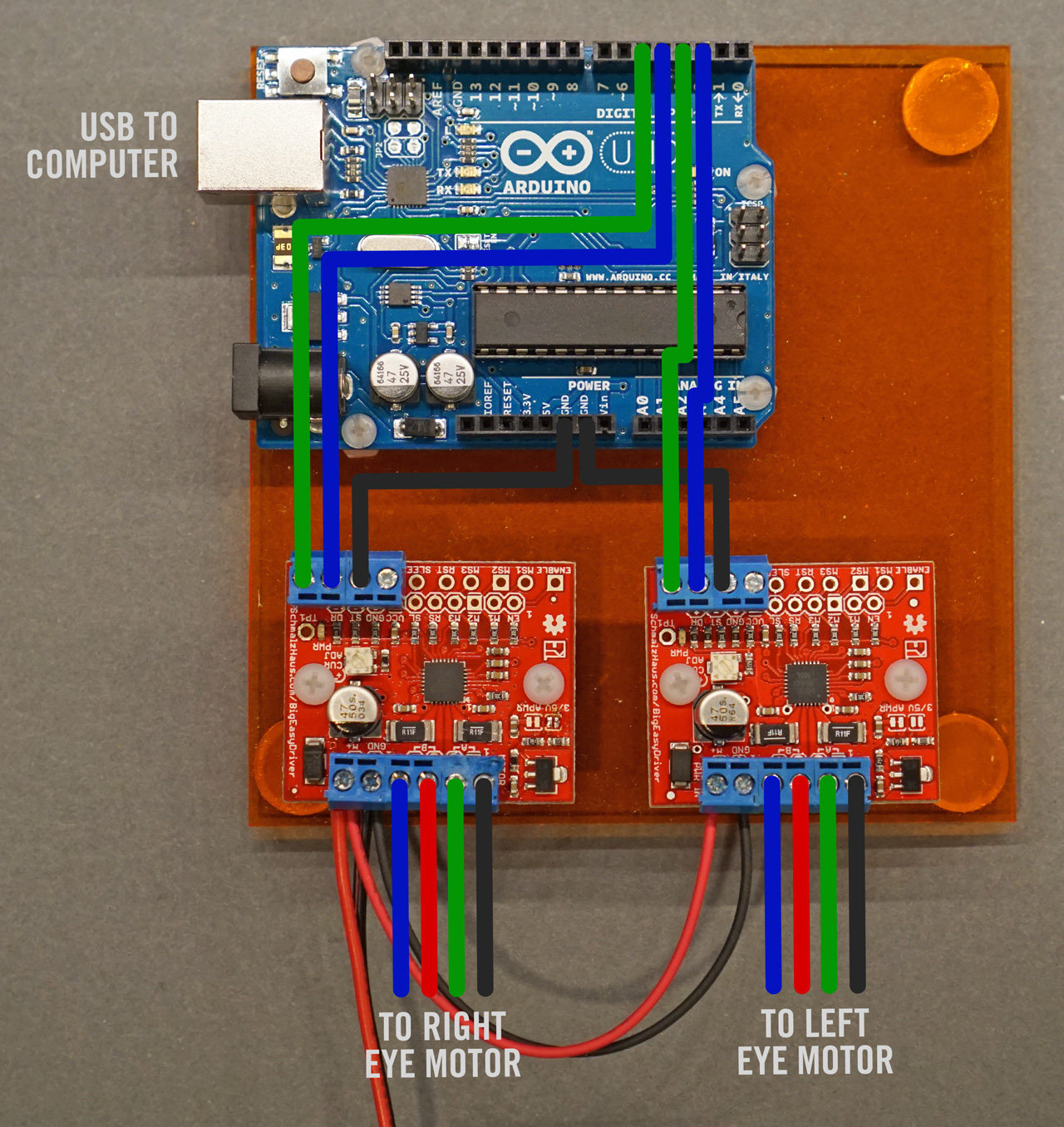
Arduino and Stepper Motor Connections
Connections Between the Arduino and the Stepper Drivers
| Signal | Color | Arduino Pin | Driver Pin |
|---|---|---|---|
| X / Left Eye Ground | Black | GND | Driver 1 – GND |
| X / Left Eye Step | Blue | Digital 2 | Driver 1 – ST |
| X / Left Eye Direction | Green | Digital 3 | Driver 1 – DR |
| Y / Right Eye Ground | Black | GND | Driver 2 – GND |
| Y / Right Eye Step | Blue | Digital 4 | Driver 2 – ST |
| Y / Right Eye Direction | Green | Digital 5 | Driver 2 – DR |
Connections Between the Stepper Drivers and the Stepper Motors
| Signal | Motor Wire Color | Driver Pin |
|---|---|---|
| X / Left Motor A+ | Black | Driver 1 – A+ |
| X / Left Motor A- | Green | Driver 1 – A- |
| X / Left Motor B+ | Red | Driver 1 – B+ |
| X / Left Motor B- | Blue | Driver 1 – B- |
| Y / Right Motor A+ | Black | Driver 2 – A+ |
| Y / Right Motor A- | Green | Driver 2 – A- |
| Y / Right Motor B+ | Red | Driver 2 – B+ |
| Y / Right Motor B- | Blue | Driver 2 – B- |
The Completed Electronics
The photo below shows all the electronics completely wired.
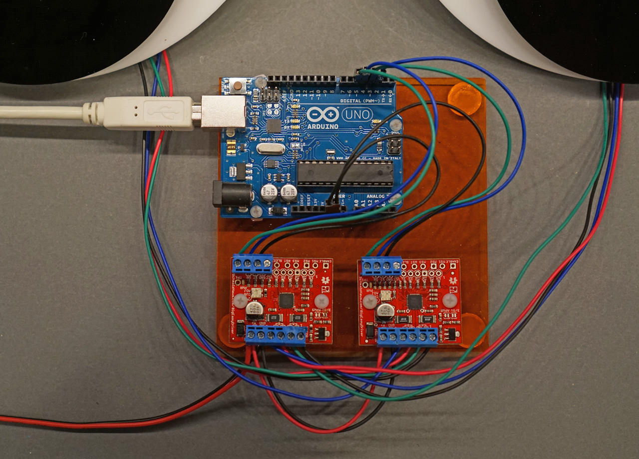
All connections completed!
Preparing the Development Environment
If you’ve never used an Arduino before, download and install the Arduino Development Environment. The Arduino website has several good tutorials on how to use the development environment to write, compile, and download code.
We’re going to use the AccelStepper library to control the stepper motors. It can be downloaded here. It is installed by unzipping the distribution zip file into the libraries subfolder of your sketchbook.
The Arduino Sketch
Create a new sketch and paste the following code into it:
// include stepper library header file
#include <AccelStepper.h>

// motor speed in steps per second
#define motorSpeed 2400

// motor acceleration in steps per second per second
#define motorAccel 32000

// left eyeball step and direction pins
#define xstep 2
#define xdir  3

// right eyeball step and direction pins
#define ystep 4
#define ydir  5

// left eyeball accelstepper instance
AccelStepper stepper1 (1, xstep, xdir);

// right eyeball accelstepper instance
AccelStepper stepper2 (1, ystep, ydir);


void setup()
{
    // set step and direction pins to outputs
    pinMode (xstep, OUTPUT);
    pinMode (xdir,  OUTPUT);
    pinMode (ystep, OUTPUT);
    pinMode (ydir,  OUTPUT);

    // left eyeball stepper setup
    stepper1.setMaxSpeed(motorSpeed);
    stepper1.setSpeed(motorSpeed);
    stepper1.setAcceleration(motorAccel);

    // right eyeball stepper setup
    stepper2.setMaxSpeed(motorSpeed);
    stepper2.setSpeed(motorSpeed);
    stepper2.setAcceleration(motorAccel);
}


void loop()
{
    // main demo loop
    LookLeft ();
    delay (1000);
    LookRight ();
    delay (1000);
    LookDown ();
    delay (1000);
    RollEyes ();
    delay (1000);
    LookLeft ();
    delay (1000);
    LookDown ();
    delay (1000);
    CrossEyed ();
    delay (1000);
    LookUp ();
    delay (1000);
    LookDown ();
    delay (1000);
}


void LookLeft (void)
{
    stepper1.moveTo(+800);
    stepper2.moveTo(+800);

    while ((stepper1.distanceToGo() != 0) || (stepper2.distanceToGo() != 0)) {
        stepper1.run();
        stepper2.run();
    }
}


void LookRight (void)
{
    stepper1.moveTo(-800);
    stepper2.moveTo(-800);

    while ((stepper1.distanceToGo() != 0) || (stepper2.distanceToGo() != 0)) {
        stepper1.run();
        stepper2.run();
    }
}


void LookDown (void)
{
    stepper1.moveTo(0);
    stepper2.moveTo(0);

    while ((stepper1.distanceToGo() != 0) || (stepper2.distanceToGo() != 0)) {
        stepper1.run();
        stepper2.run();
    }
}


void LookUp (void)
{
    stepper1.moveTo(+1600);
    stepper2.moveTo(-1600);

    while ((stepper1.distanceToGo() != 0) || (stepper2.distanceToGo() != 0)) {
        stepper1.run();
        stepper2.run();
    }
}


void RollEyes (void)
{
    stepper1.moveTo(+3200);
    stepper2.moveTo(+3200);

    while ((stepper1.distanceToGo() != 0) || (stepper2.distanceToGo() != 0)) {
        stepper1.run();
        stepper2.run();
    }

    stepper1.setCurrentPosition (0);
    stepper1.moveTo(0);
    stepper2.setCurrentPosition (0);
    stepper2.moveTo(0);
}


void CrossEyed (void)
{
    stepper1.moveTo(-800);
    stepper2.moveTo(+800);

    while ((stepper1.distanceToGo() != 0) || (stepper2.distanceToGo() != 0)) {
        stepper1.run();
        stepper2.run();
    }
}
Running The Sketch
To compile, download, and run the sketch, follow these steps:
- Plug the Arduino into the computer’s USB port.
- Select the Arduino’s serial port from the Tools : Serial Port menu.
- Compile, download, and run the code by clicking the right arrow in the code editing window.
We want the eyeballs to be in a known position (looking straight down) when starting the Arduino. Follow these steps to move the eyeballs to the starting position and to start the Arduino with the eyeballs in the starting position:
- Unplug the Arduino from the computer’s USB port.
- Rotate both pupils until they’re looking straight down.
- Plug in the DC motor supply.
- Plug the Arduino into the computer’s USB port.
At this point, the eyeballs should start moving following the sequence outlined in the loop section of the sketch. This sequence is left : right : down : rolleyes : left : down : crosseyed : up : down.
Next Steps
In part three of this series of posts, we’re going to use OpenCV to detect faces and make the googly eyes track a person as they move around a room. This will first require the installation of Python, NumPy, OpenCV, and PySerial. Then we’ll modify the example OpenCV Python face detection code to send the location of a face on a webcam to the Arduino. Lastly, we’ll modify the Arduino code to listen for the location of a face and move the steppers to point the eyeballs towards that location.