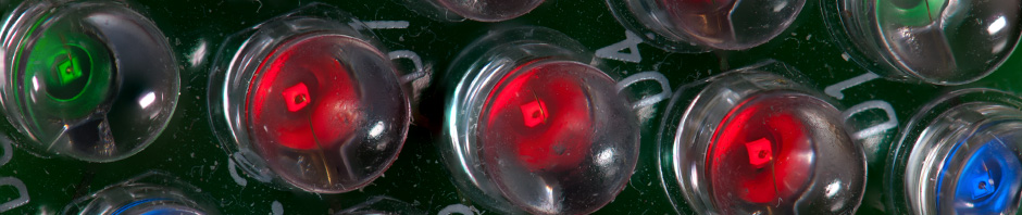

An army of miniature traffic barrels waiting to assault your morning commute.
I designed a miniature traffic barrel with a blinking warning light then built a whole army of them to slow down traffic on my desktop. The warning light was a challenge because it has a lot of detail, it holds a real LED, and it’s quite small. After designing the barrel and warning light, I chose a PIC12F1612 8-pin microcontroller to make the LED blink. It requires fewer parts than a 555 timer circuit, uses less power, and the blink pattern is fully programmable. Read on to learn how to design a traffic barrel complete with a functioning, battery-powered warning light.
The Traffic Barrel

The 3D model of the completed traffic barrel in Autodesk Fusion.
I drew the traffic barrel in Autodesk Fusion. It consists of three components: the main barrel, the “weighted” ring at the base, and the warning light. The warning light is divided into two bodies. The first body is for the base of the light. The second body is for the lens. This facilitates using different filaments for each part of the warning light in the slicing software.
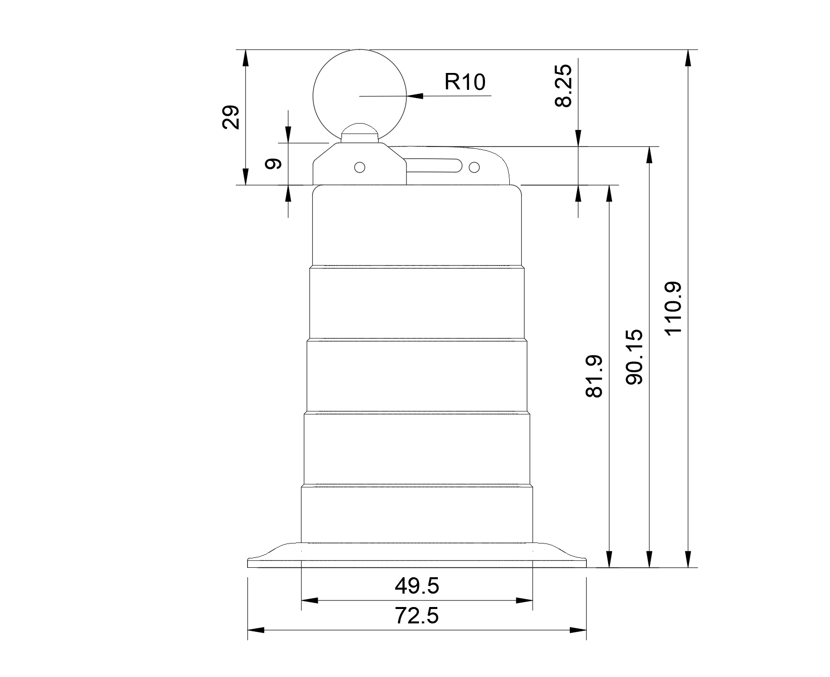
Dimensioned drawing of the traffic barrel.
The main body of the barrel is roughly 82 mm high. The handle adds an extra 8 mm and the light, an additional 29 mm. This is roughly a 1:10 to 1:12 scale model of a real traffic barrel which is approximately 1 m high with a 200 mm diameter warning light.
Barrel
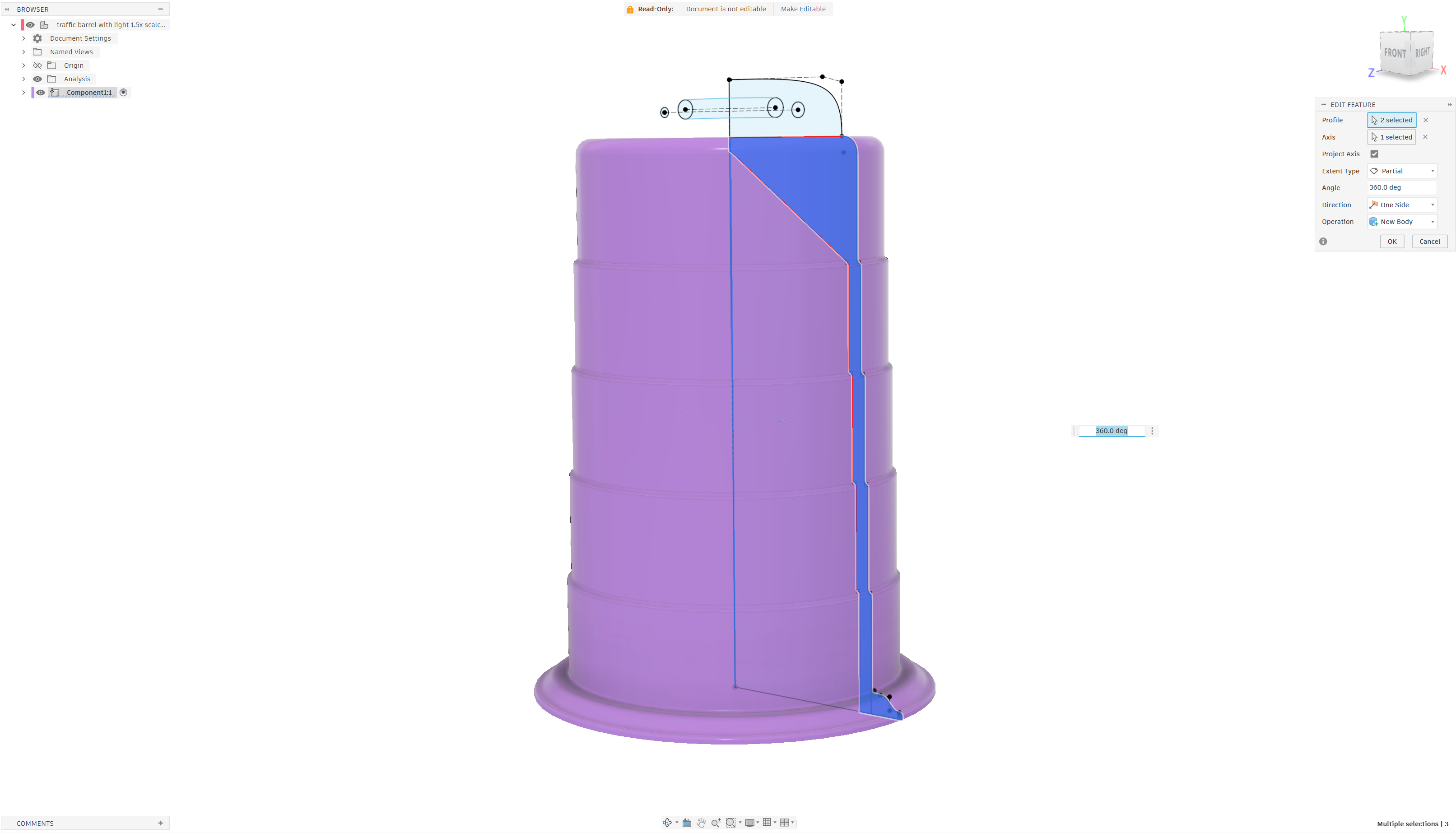
The main body of the barrel is a 360° rotation of a sketch profile.
The main body of the traffic barrel has a relatively simple design. The hardest part was getting the dimensions correct. I went with 15 mm rings with the bottom and top rings 15% larger to accommodate the flared base and rounded top edge. The base ring diameter, excluding the flared base, is 49.5 mm. The seams between each ring rise and run 0.6 mm up and inward. The walls are 2 mm thick. The top of the barrel has a 45° slant to allow printing without supports. Rotating the profile sketch 360° build the main part of the body.
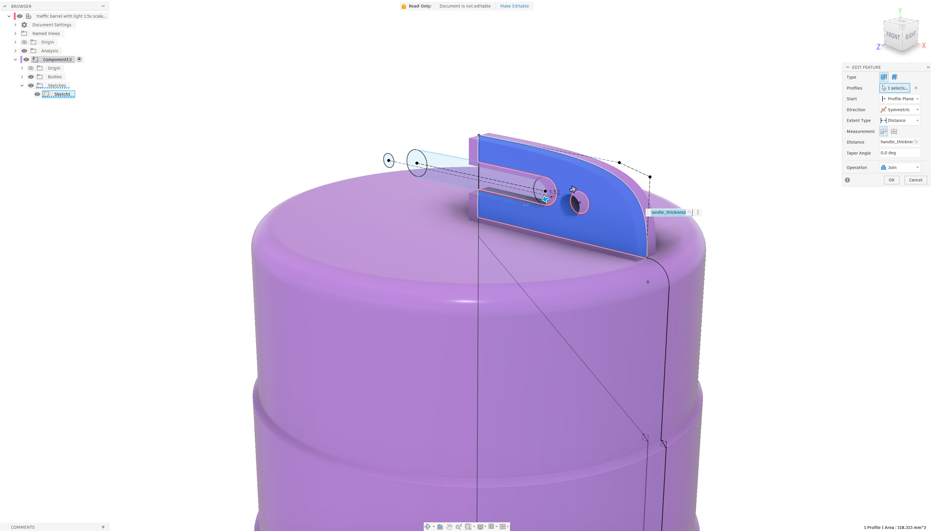
Extruding the barrel handle and warning light mounting holes.
The handle is a 1.5 mm symmetric extrusion of a sketch profile then a mirror operation. The holes in the barrel handle will align with the holes in the warning light. The ends of the handle do not quite go all the way to the edge of the barrel to keep them from being extruded over the edge of the barrel.
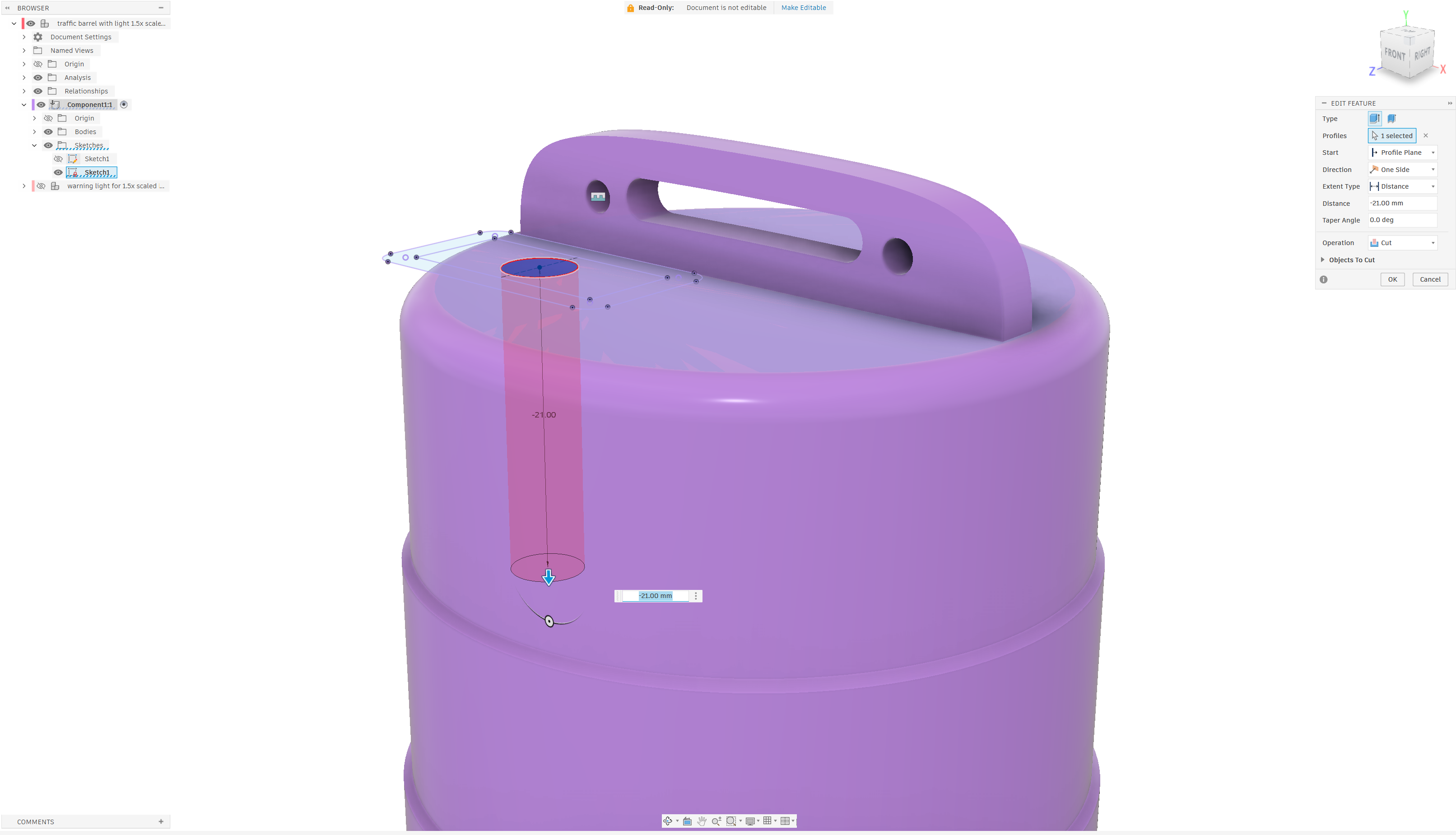
The barrel with the completed handle and the extrusion for the warning light’s wires.
I used a projected sketch profile to locate the center of the warning light and place a 5 mm hole through the top of the barrel. This hole is for the warning light’s wires.
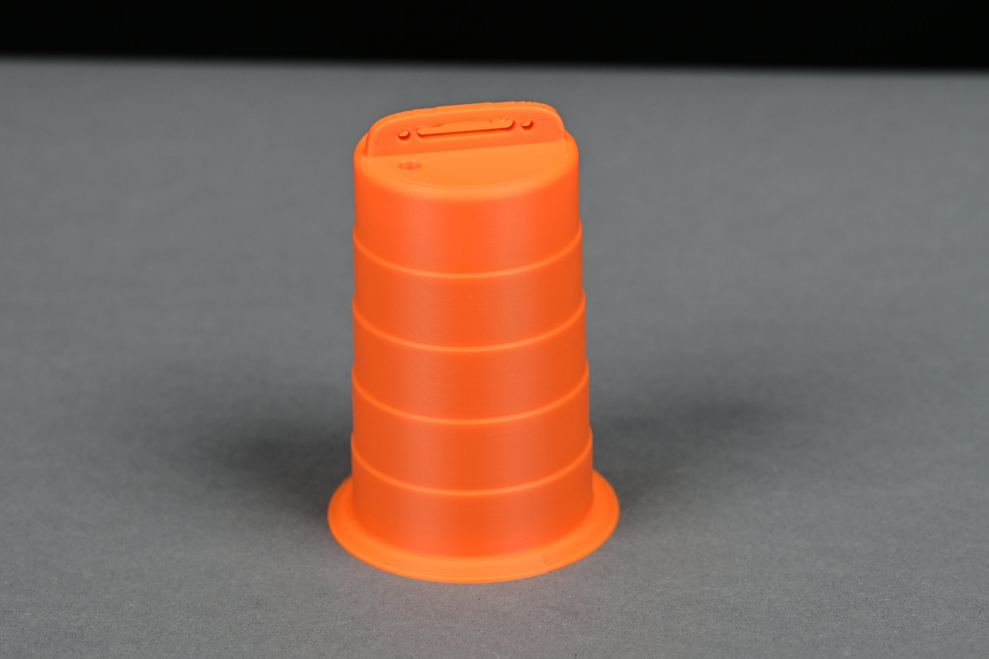
The 3D printed barrel main body.
I printed the barrel in Bambu Lab’s basic orange PLA using 0.20 mm slices and no supports. If I were designing this again, I’d make the handle a bit shorter to eliminate some of the issues with the large bridge distance.
Weighted Base
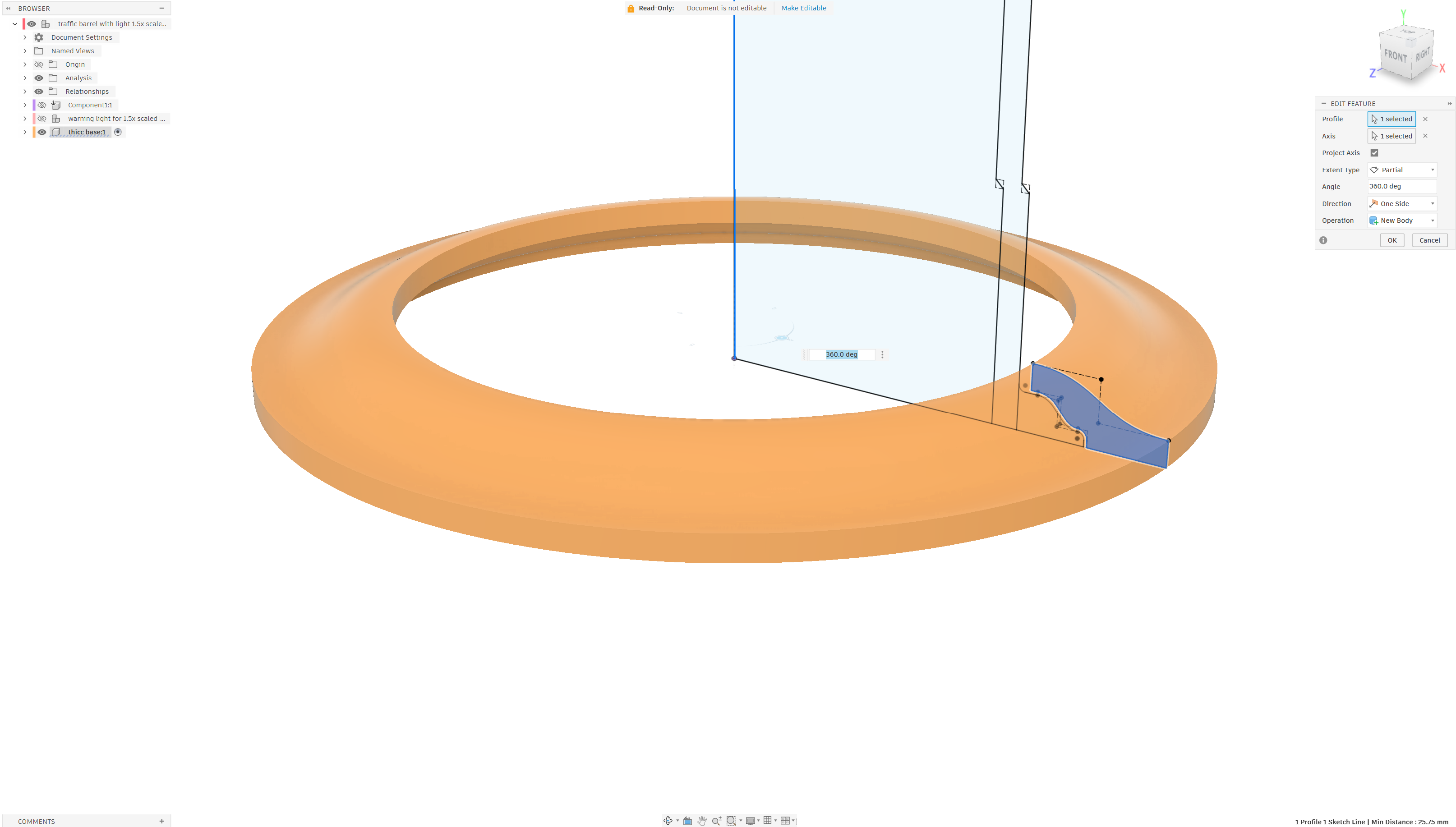
Rotation of the profile to create the weighted base.
The weighted base is another 360° rotation. The profile is offset from the main body of the barrel by 0.2 mm. I applied a fillet to the top outer edge to soften it a bit.
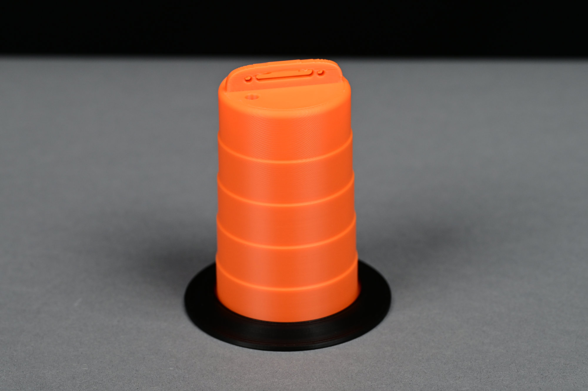
The printed barrel with the “weighted” base ring.
I printed the barrel in Bambu Lab’s basic black PLA using 0.16 mm slices and supports.
Warning Light
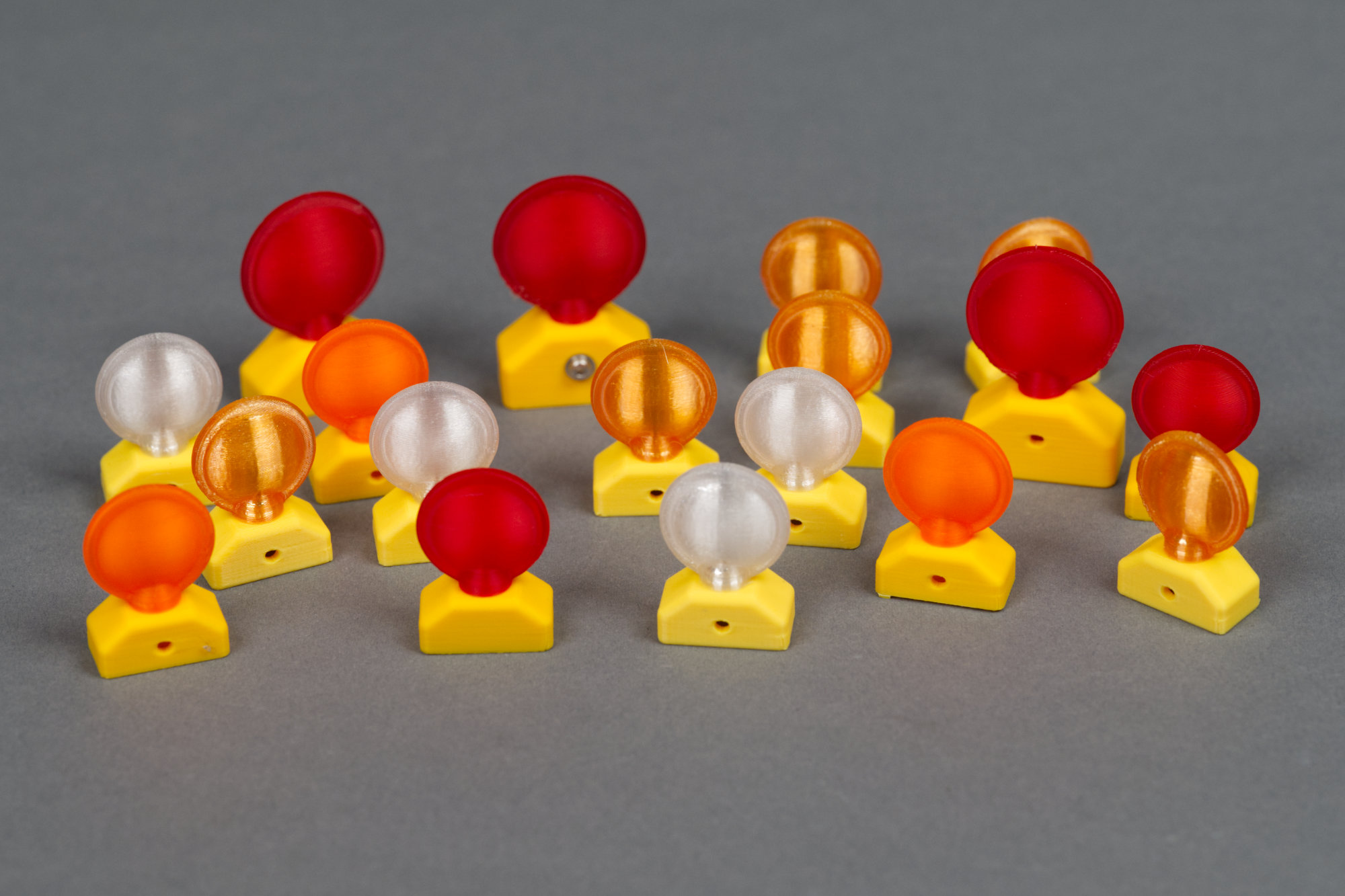
Many of the different warning light experiments: two different sizes and four different color combinations.
The warning light, especially hollowing it out to accommodate a T1 3 mm round LED, was the most difficult part of the project. I started with a light with a 25 mm diameter lens but this was too big for the barrel. I reduced the lens diameter to 20 mm and this looked much better.
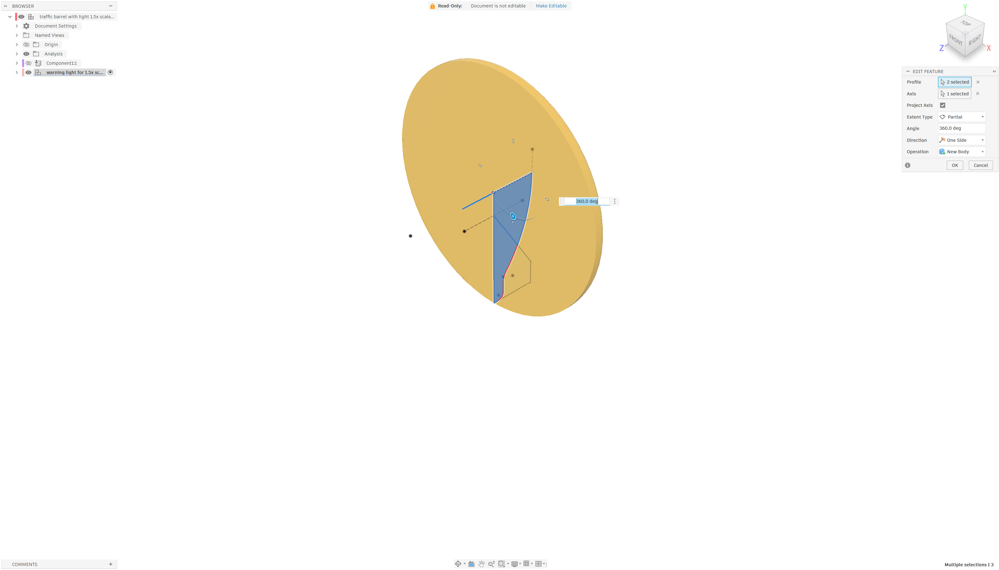
Create the lens.
The first step was to draw the lens using a 360 revolution of a sketch profile around the z axis. This created half the lens.
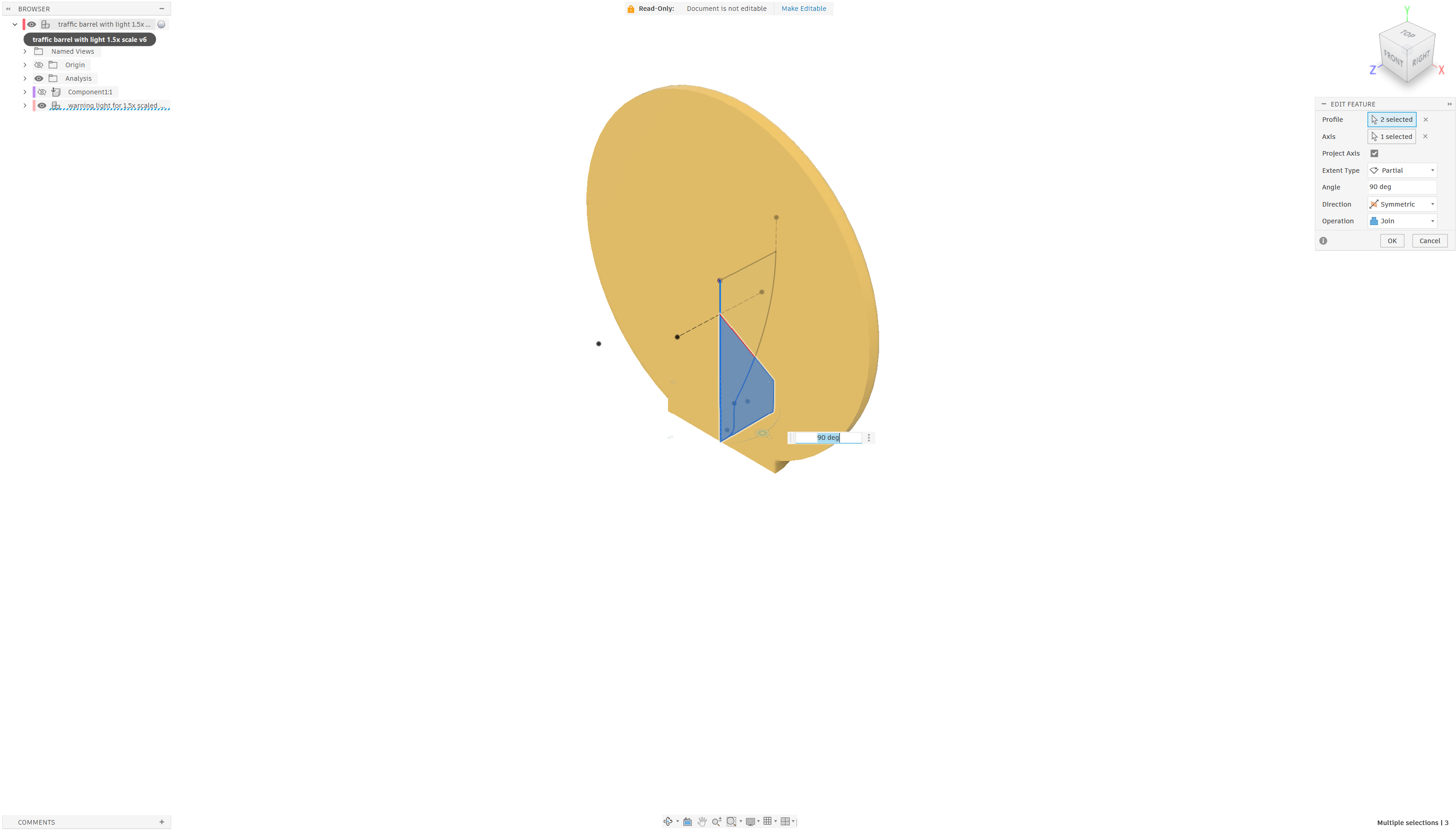
Create the neck.
The second step was to draw the neck using a 90 degree symmetric revolve around the y axis. This creates half the neck on the same side of the xy plane as the lens.
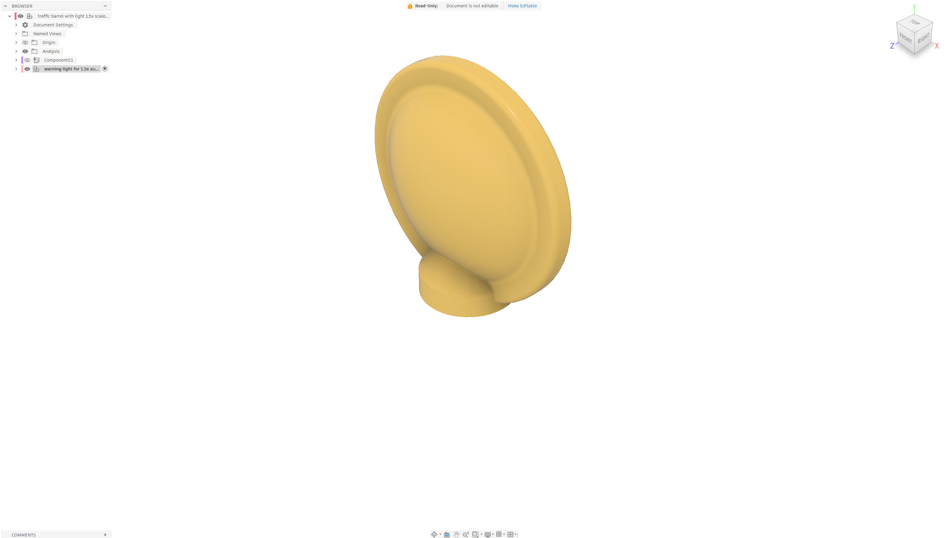
Mirror to create the complete lens and neck.
Mirroring the combined body produces the full lens and neck.
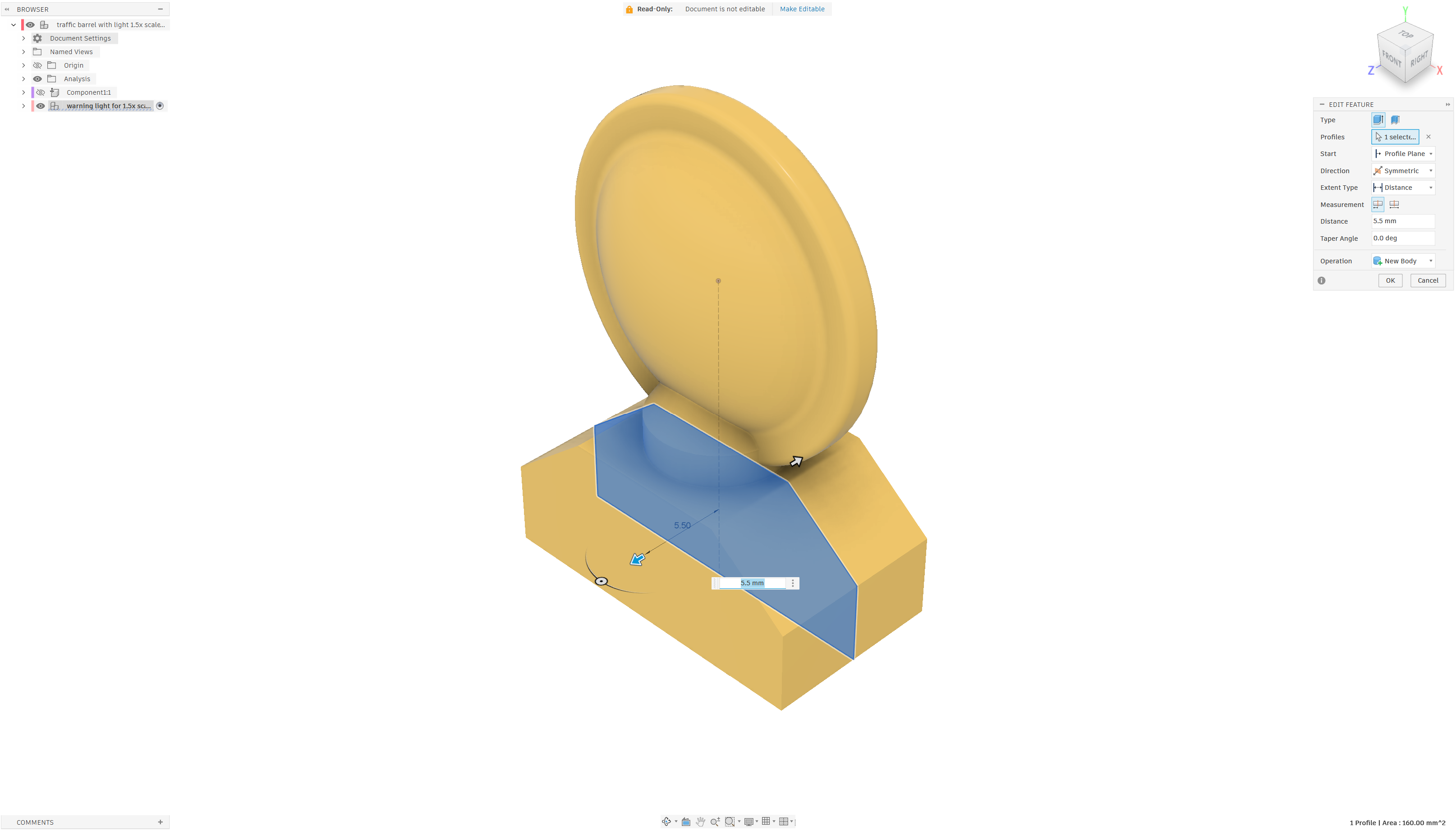
Sketch and extrude the battery box.
The next step was to draw and extrude the base into a new body in the same component. The Bambu slicer lets you assign different colors to each body when importing a component for 3D printing from Fusion. We’ll assign the lens body a translucent filament color and the base body an opaque yellow filament.
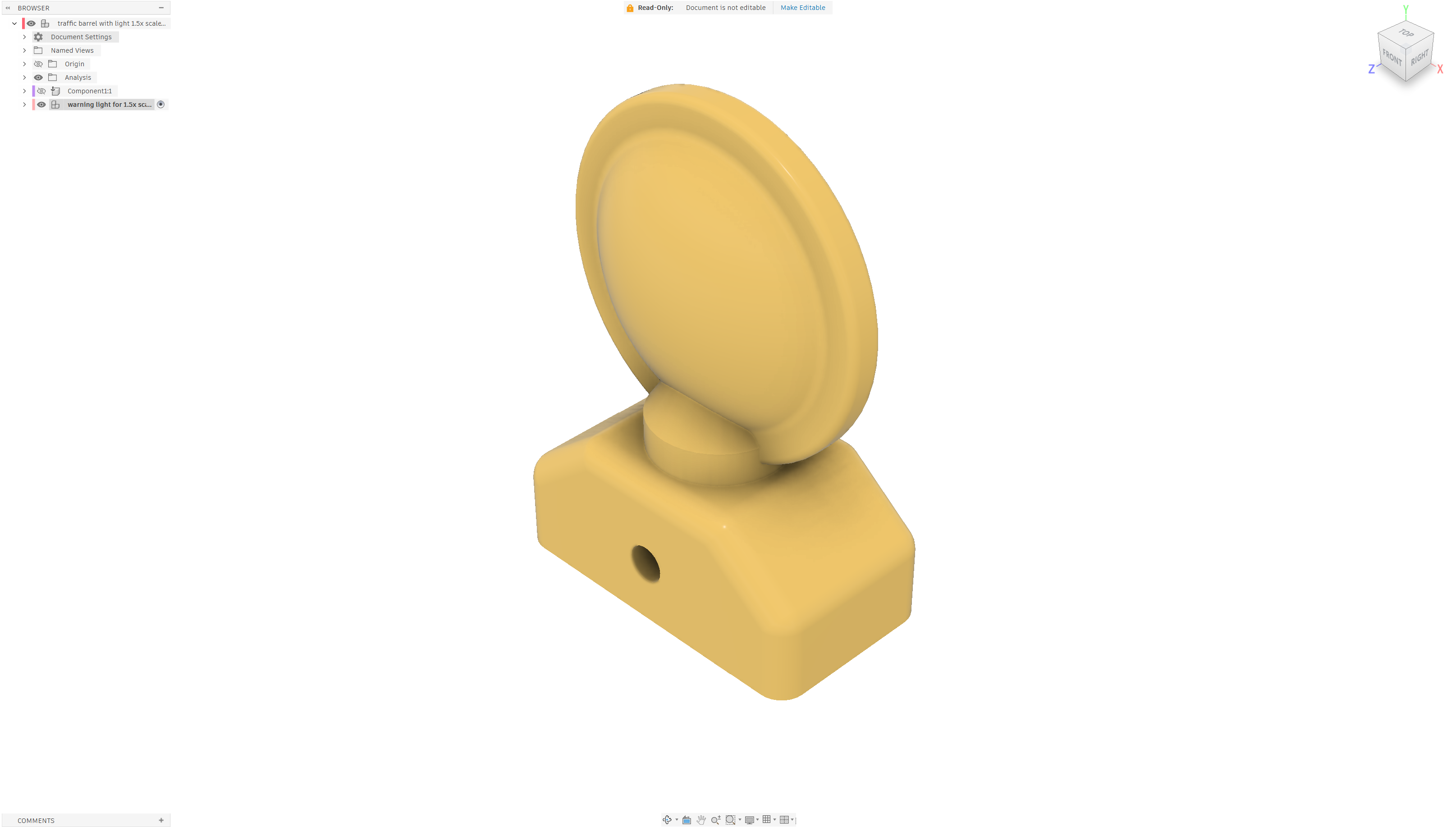
Apply some fillets to take the edges off.
Next I added a hole to mount the lens to the barrel and used the fillet tool to round the edges of the base.
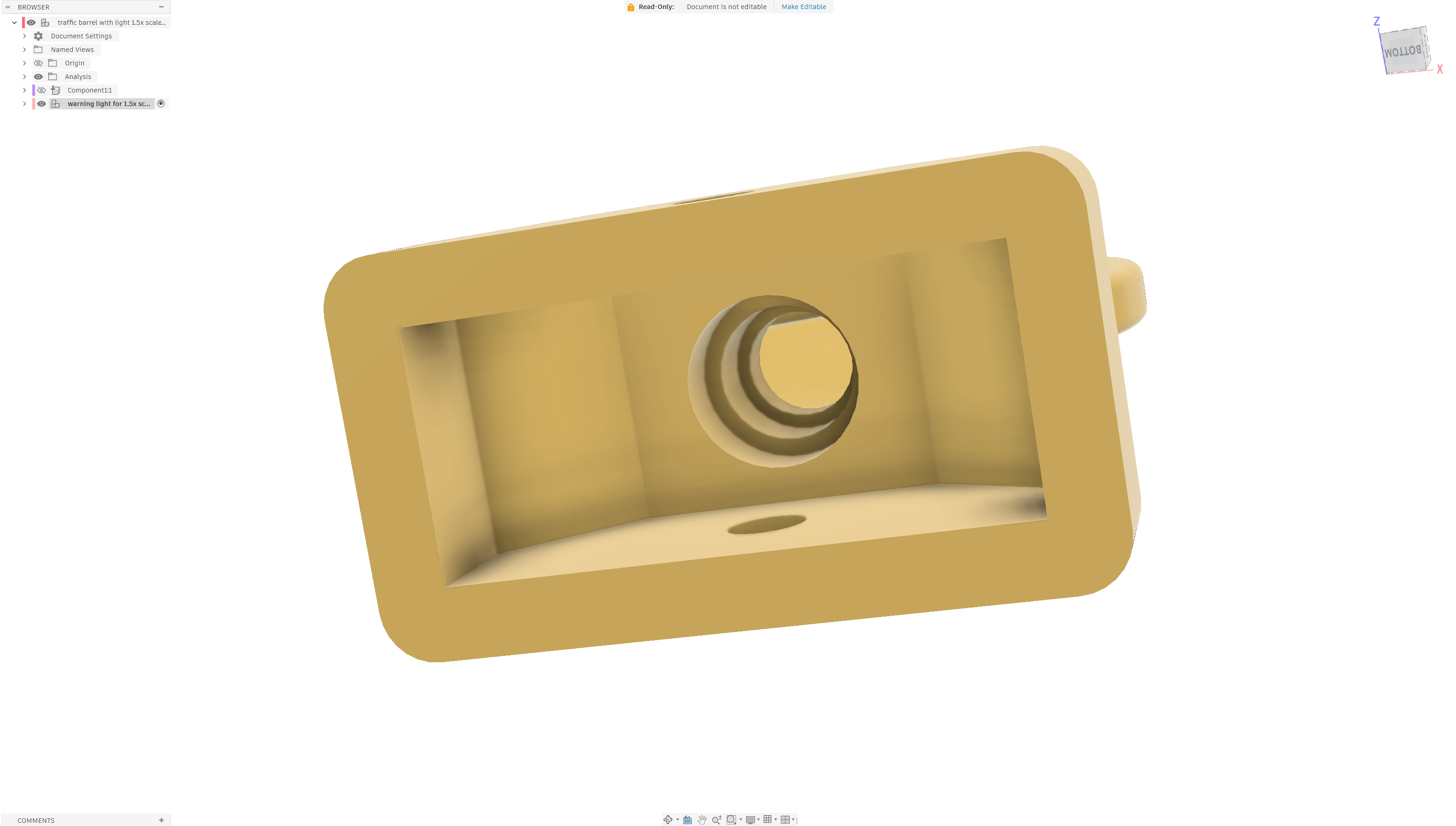
Use the hole, shell, sketch, and extrude tools to hollow out the lens and neck to accommodate a T-1 3 mm LED.
The last step was to use various combinations of the hole, shell, sketch, and extrude tools to hollow out the lens and create a friction fit for a T-1 3 mm LED in the base.
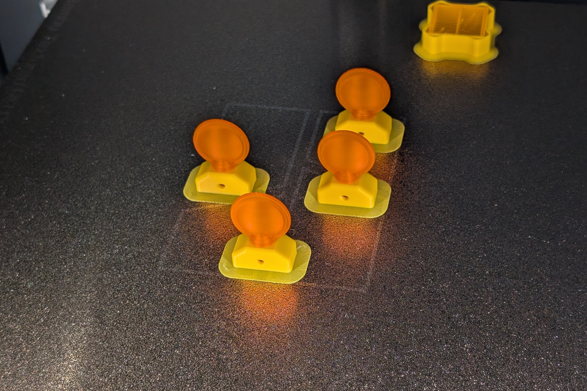
Another batch of warning lights fresh off the printer. These are in Bambu Lab’s sunflower yellow basic PLA and orange translucent PLA.
To print these, I selected the component rather than the lens or base bodies in Fusion for 3D printing. When the component’s 3MF file is imported into the Bambu slicer, the slicer will let you assign a different filament to each body but print both bodies as a single unit. I used a 0.16 mm layer height for the warning light. I experimented with four color combinations:
- Sunflower yellow base with red translucent lens using Bambu’s basic PLA and translucent PLA filaments.
- Sunflower yellow base with orange translucent lens using Bambu’s basic PLA and translucent PLA filaments.
- Yellow base with clear lens using Bambu’s basic PETG and translucent PETG filaments.
- Yellow base with orange lens using Bambu’s basic PETG and translucent PETG filaments.
I preferred the PLA combinations over the PETG combinations although honestly the yellow basic PETG and translucent orange PETG combination most closely resemble the colors of a real barricade warning light. Due to the wasted time and material involved with changing filaments on my printers on each print job, I always printed these four at a time.
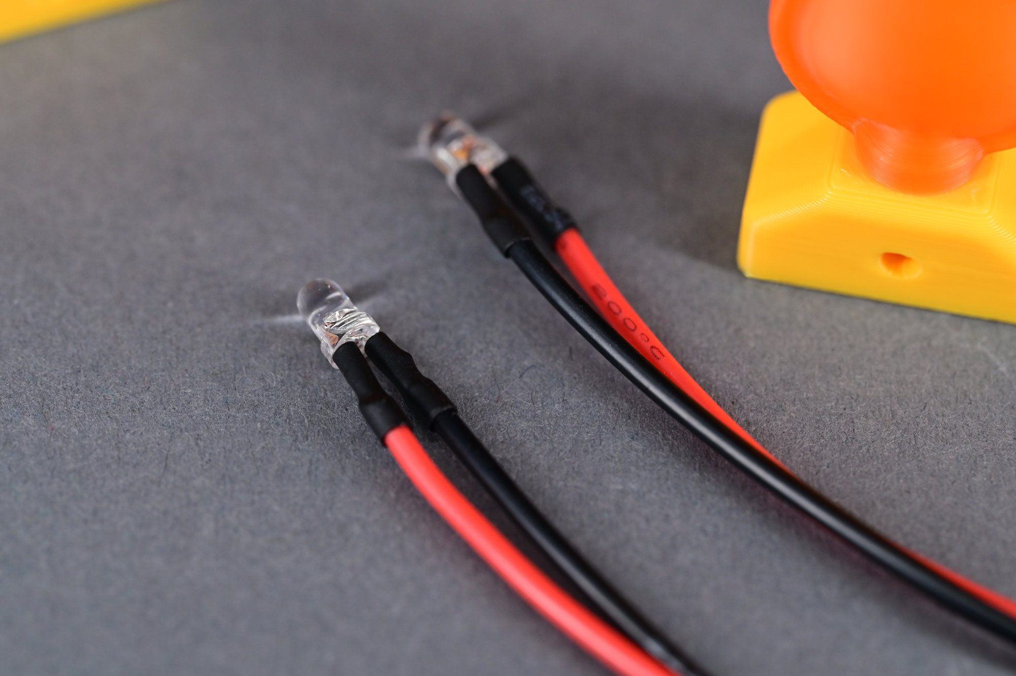
Cheap no name orange LEDs with wires attached and heat shrink tubing.
I have a large selection of generic T-1 3mm LEDs in various colors. I soldered 150 mm silicone wires to a bunch of these then used heat shrink to insulate and protect the connections. I did not install a current limiting resistor since I plan on putting that on the board that will blink the LEDs.
Since all the LEDs have clear lenses, I have to power them up to see what color they are. I used red LEDs in the red lenses and orange LEDs in the orange lenses. I thought about putting a yellow, green, blue, or white LED in one of the clear lenses.
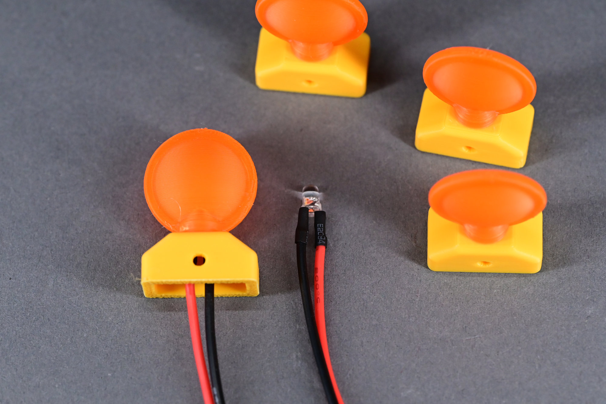
Push the LED into the base of the warning light. The LED is rotated so that one lead is on each side of the screw hole.
The LED should fit snugly inside the neck of the warning light. The LEDs are rotated in the neck such that the wires will extend from the warning light on either side of the M2 screw that holds the warning light to the barrel.
Vinyl Stripes
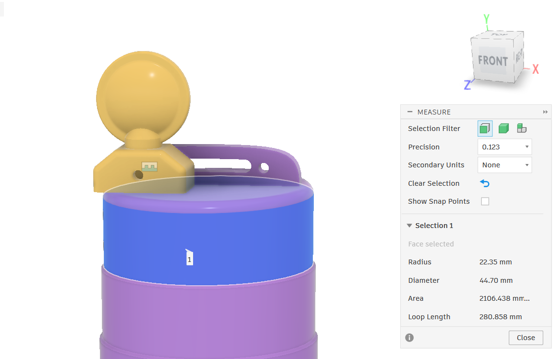
Using the info tool in Fusion to get the diameter of each of the barrel’s rings.
The next step was to cut reflective vinyl stickers to place on the traffic barrel. The ordering of the stripes from top to bottom is orange, white, orange, and white with no stripe on the very bottom ring. There’s actually a standard for this.
I used Fusion’s measurement tool to get the diameter of each barrel ring. Multiplying by Pi gives the circumference. Finally I added 1 mm to the circumference to get the finally length of each sticker. All the stickers are 11 mm tall. The colors and lengths of each sticker for the barrel from top to bottom are:
- Orange: 11 x 141.43
- White: 11 x 145.20
- Orange: 11 x 148.97
- White: 11 x 152.74
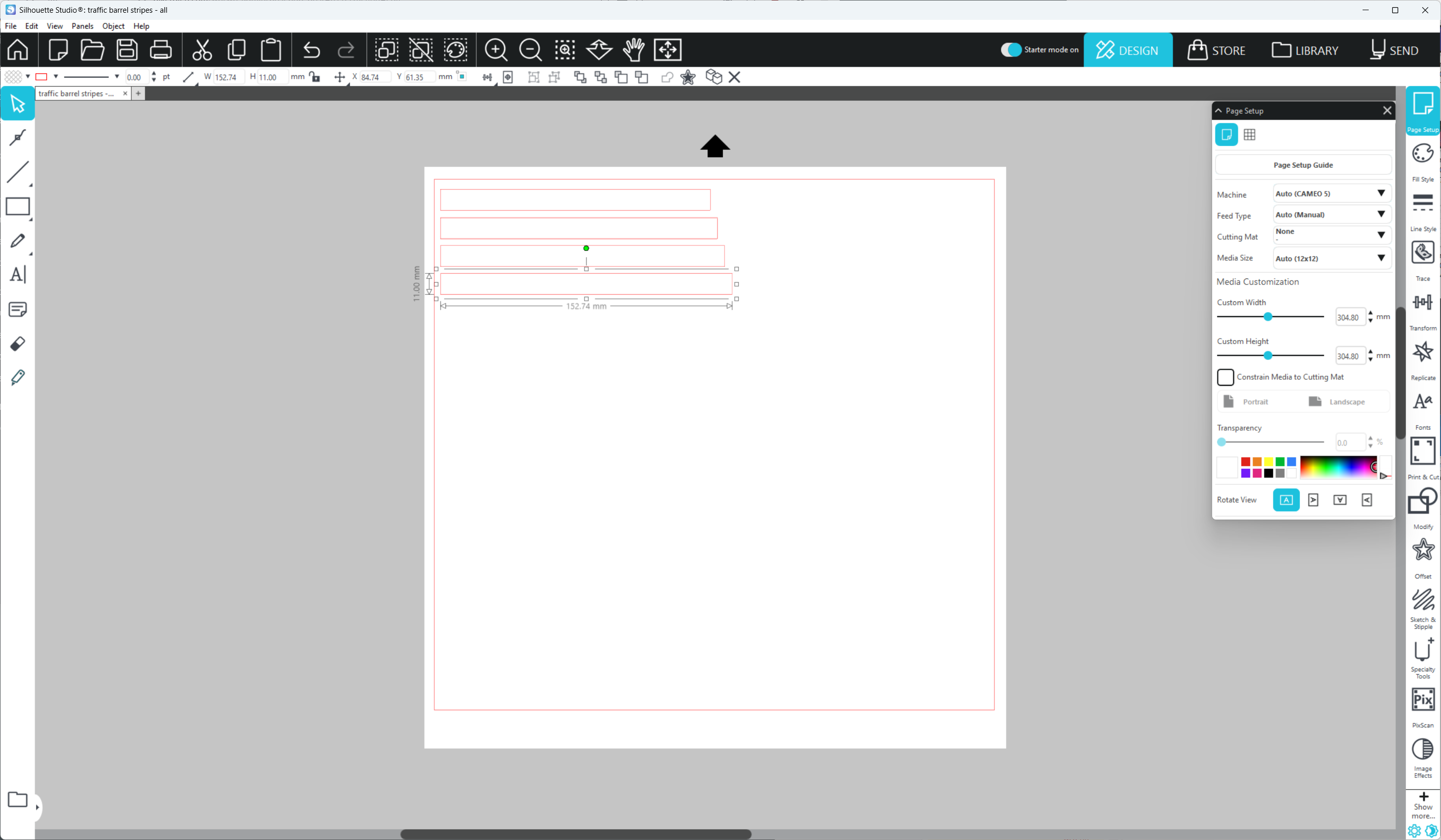
The barrel stripes in Silhouette Designer.
I drew these in Silhouette Studio then cut them out of Oracal Oralite reflective vinyl. Since the vinyl is relatively expensive at $5 per square foot in small quantities, I only cut the orange stickers out of the orange vinyl and the white stickers out of the white vinyl. I also cut as many stickers as I could fit across the sheet at once.
Putting it All Together

The barrel with the warning light attached and the black weight ring around its base.
To finish it up, I threaded the wires through the hole on the top of the barrel and secured the warning light to the barrel with an M2 x 16 mm screw, washer, and nut.
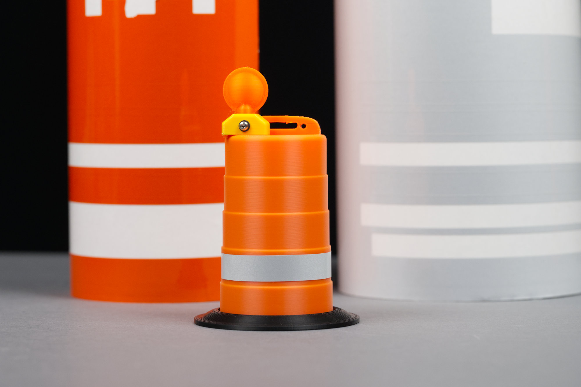
The barrel with the first white stripe applied.
Next, I applied the reflective vinyl stickers to each ring of the barrel. I started at the back of the barrel and wrapped each vinyl sticker completely around the barrel paying attention to the color ordering and sticker sizes. The vinyl is somewhat stretchy so I appled just enough tension to keep the vinyl from folding in on itself as I adhered the vinyl to the barrel. I pushed air bubbles out as I went along. I periodically backed up, if necessary, to eliminate a bubble or re-center the vinyl.
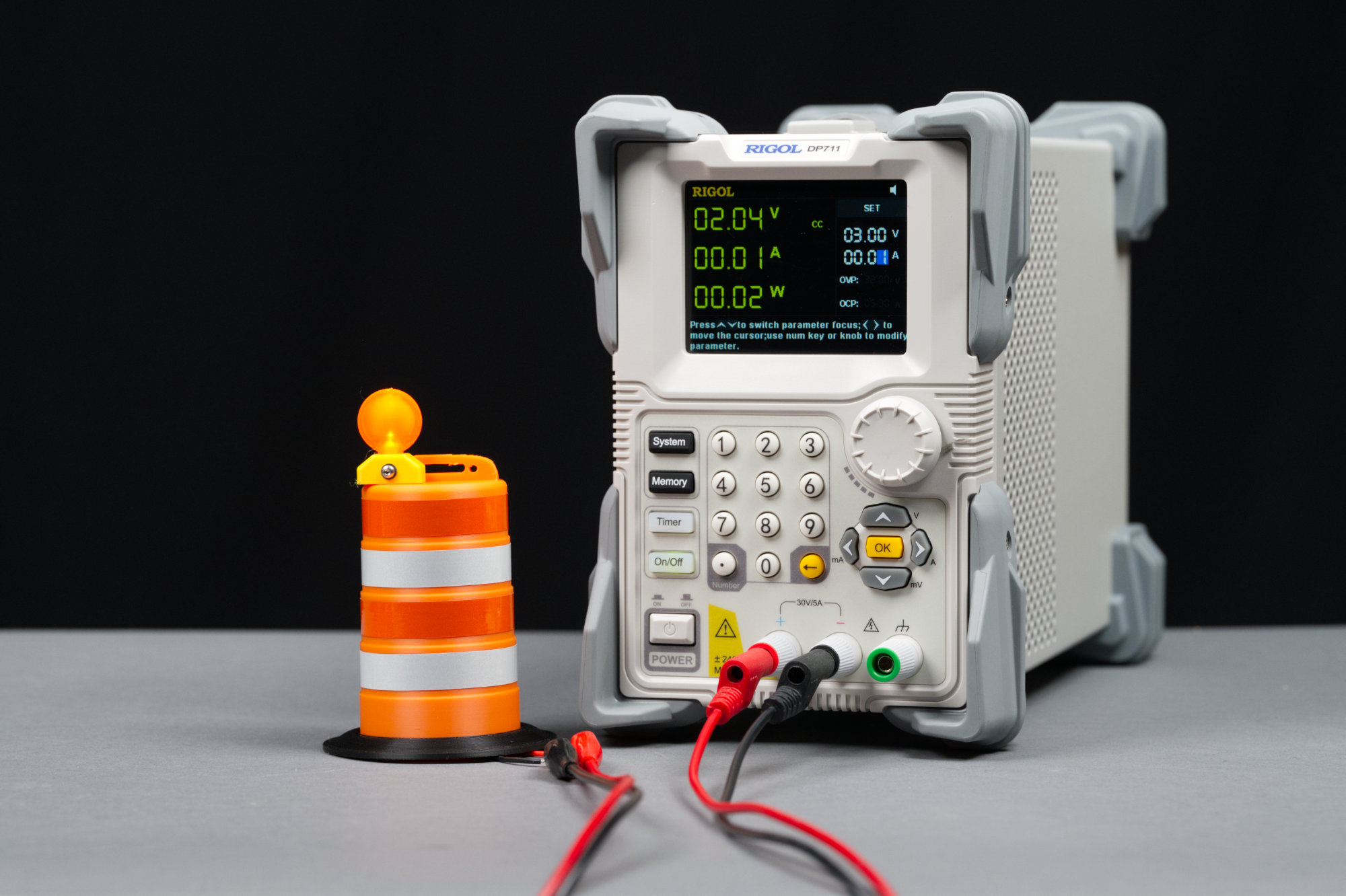
Measuring the LEDs forward voltage at a forward current of 10 mA using a bench power supply in constant current mode.
The first moment of truth: will the LED light? I used a bench supply set to constant current mode to drive the LED at 10 mA. And it worked! It’s hard to tell in the photo above, but the LED is indeed lit. The bench supply also let me know the forward voltage of this particular LED is 2.04 V which is reasonable for an orange LED.
Late Update

Twos barrels viewed from the back: one with the original handle and a second with a narrower handle.
Late update: I did end up printing a barrel with a narrower handle. The bridging is much better on the barrel with the narrower handle as you can see in the photo above.
Making it Blink
To make the LED blink, I’m going to use an 8-pin PIC12F1612 microcontroller powered by a small, single-cell LiPo battery. The PIC12F1612 is a good choice for this project because it will operate from 2.3 V to 5.5 V which completely overlaps the range of the LiPo battery’s output voltage.
Over that entire range, when clocked by the internal 31 kHz oscillator, the PIC12 consumes no more than about 25 uA. This is basically nothing compared to the current of the blinking LED. And I can’t think of any reason someone would use a 555 when there’s a microcontroller and software solution that uses less power, has more flexibility, and has a smaller parts count.
Blinker Board Hardware Version 1
I made two versions of the blinker hardware. The first is a robust, slightly larger board featuring everything needed for development and some backup components. The second is an optimized board with a minimal part count and no development / debugging / programming headers. We’ll start with the first version, write the software, and bring up the hardware before moving to the second, optimized version.
Schematic
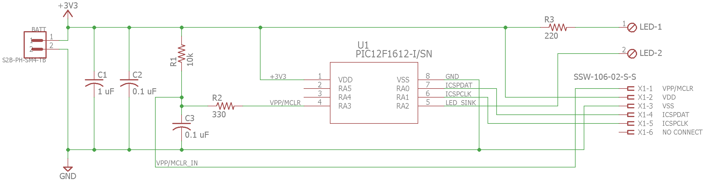
Blinker board schematic.
The schematic for the blinker board is shown in the illustration above. Moving left to right, there’s a JST PH connector for the LiPo battery, a bulk capacitor, a decoupling capacitor, a pullup resistor and filter for the PIC12’s /MCLR input, the PIC12, a current limiting resistor for the LED, and finally, a connector for the LED and the programming connector for the PIC12.
Layout
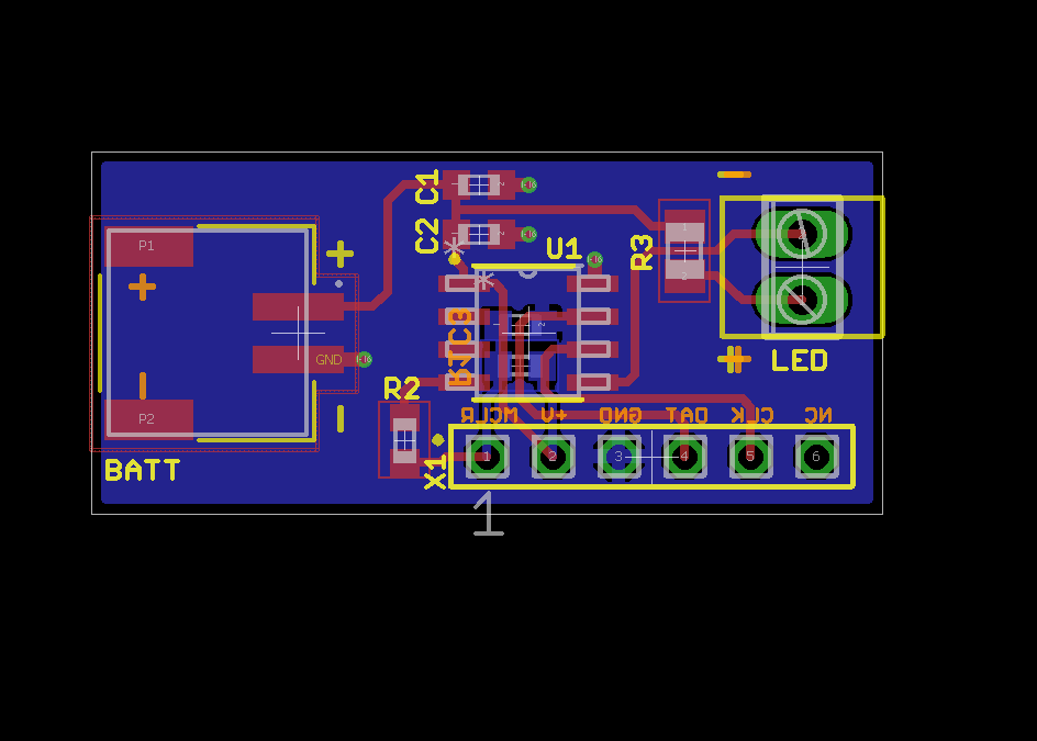
Blinker board layout
The image above shows the board layout: battery connector on the left, LED connector on the right, and everything else in between.
Bill of Materials
The bill of materials is listed in the table below.
| Designator | Description |
|---|---|
| C1 | 1 uF 0603 (not used) |
| C2 | 0.1 uF 0603 |
| C3 | 0.1 uF 0603 (not used) |
| R1 | 10k 0603 (not used) |
| R2 | 330 0603 |
| R3 | 220 0805 |
| U1 | Microchip PIC12F1612-I/SN |
| X1 | 0.1″ 0.025″ square post six position header (not used) |
| Battery Connector | S2B-PH-SM4-TB (JST PH 2 mm, 2 position) |
| Battery | Sparkfun PRT-13853 110 mAh Li-Ion Battery |
| LED Connector | Phoenix Contact 1725656 |
Notes:
- All capacitors are X5R or X7R and rated for at least 10 V.
- All resistors are rated for at least 1/10 W.
Assembled
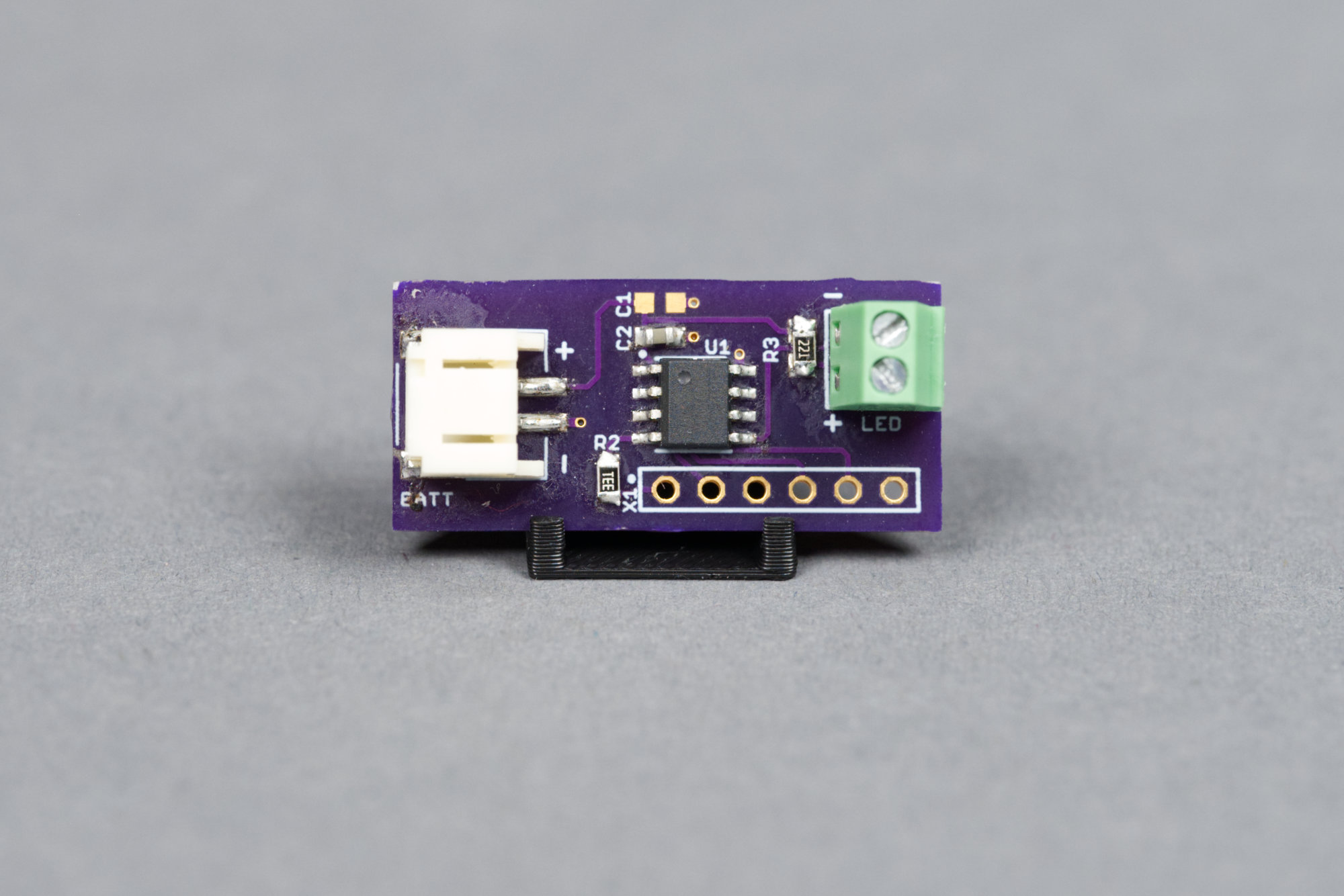
The initial version of the board.
A photo of the assembled board is shown in the image above.
Blinker Board Software
The blinker board software initializes the PIC12, selects the 31 kHz oscillator, and sets the unused inputs and outputs to a state that minimizes their current consumption. Next, it begins blinking the LED at 65 flashes per minute and a 10 % duty cycle. Yep, there’s a standard for this too. That’s all the code does.
#include <xc.h>

// CONFIG1
#pragma config FOSC = INTOSC
#pragma config PWRTE = ON
#pragma config MCLRE = OFF
#pragma config CP = OFF
#pragma config BOREN = ON
#pragma config CLKOUTEN = OFF

// CONFIG2
#pragma config WRT = OFF
#pragma config ZCD = OFF
#pragma config PLLEN = OFF
#pragma config STVREN = ON
#pragma config BORV = LO
#pragma config LPBOR = ON
#pragma config LVP = ON

// CONFIG2
#pragma config WDTE = OFF

#define _XTAL_FREQ 31000

void main (void)
{
  OSCCONbits.IRCF = 0b0000;
  OSCCONbits.SCS = 0b10;

  ANSELA = 0x00;
  OPTION_REGbits.nWPUEN = 0;
  WPUAbits.WPUA3 = 1;

  TRISAbits.TRISA0 = 0;
  TRISAbits.TRISA1 = 0;
  TRISAbits.TRISA2 = 0;
  TRISAbits.TRISA4 = 0;
  TRISAbits.TRISA5 = 0;

  LATAbits.LATA0 = 0;
  LATAbits.LATA1 = 0;
  LATAbits.LATA2 = 0;
  LATAbits.LATA4 = 0;
  LATAbits.LATA5 = 0;

  while (1) {
    LATAbits.LATA2 = 0;
    __delay_ms (92);
    LATAbits.LATA2 = 1;
    __delay_ms (831);
  }

  return;
}
Note that MCLRE doesn’t do anything unless LVP is set to OFF.
Testing it Out
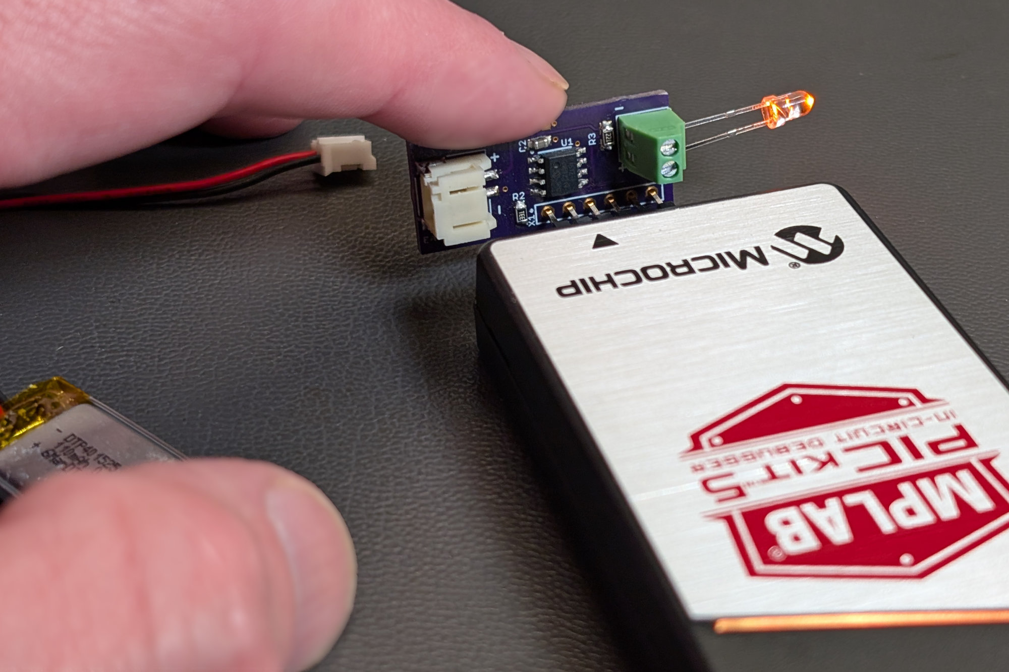
It’s awkward but it works for programming. I would not want to do this while running the debugger.
Since I’m building a lot of these and am not making a lot of changes to the software, I opted to skip installing the header and instead just hold the board and programmer in place while programming the PIC12.
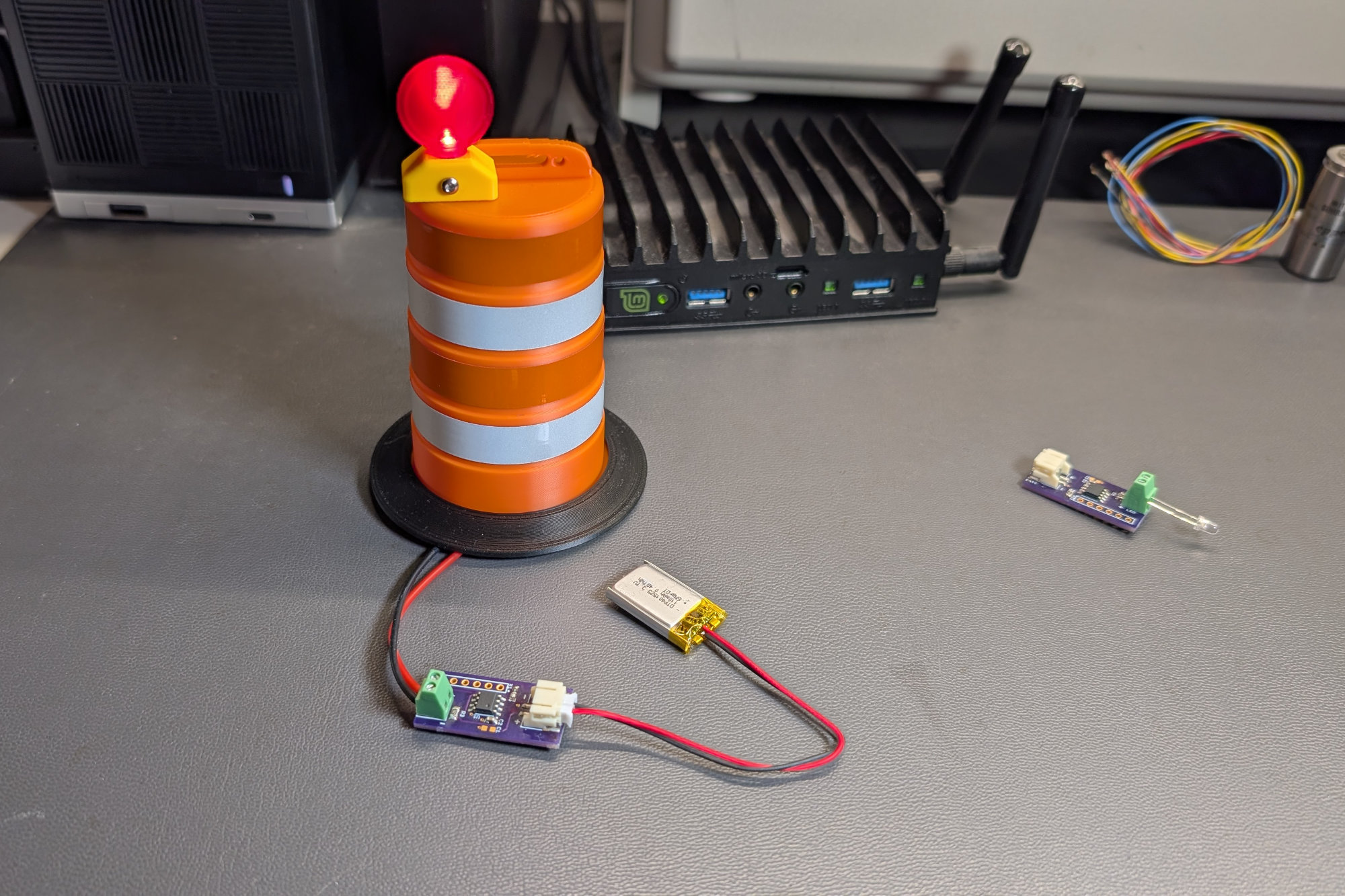
The blinker board connected to the LED on the traffic barrel and the LiPo battery.
Everything is connected and the warning light is blinking now!
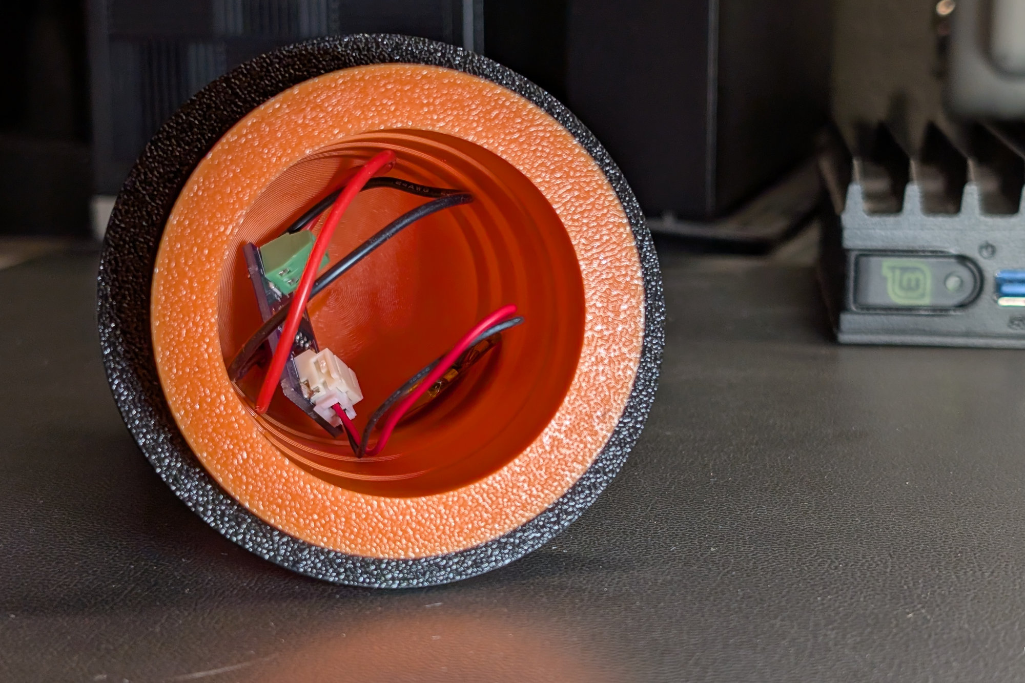
The blinker board, LiPo battery, and wires stuffed in the bottom of the barrel.
The battery, blinker board, and wires easily fit inside the traffic barrel. I may make a little holder to hold everything together that the barrel could sit over, but for now, this is good enough.
Battery Life
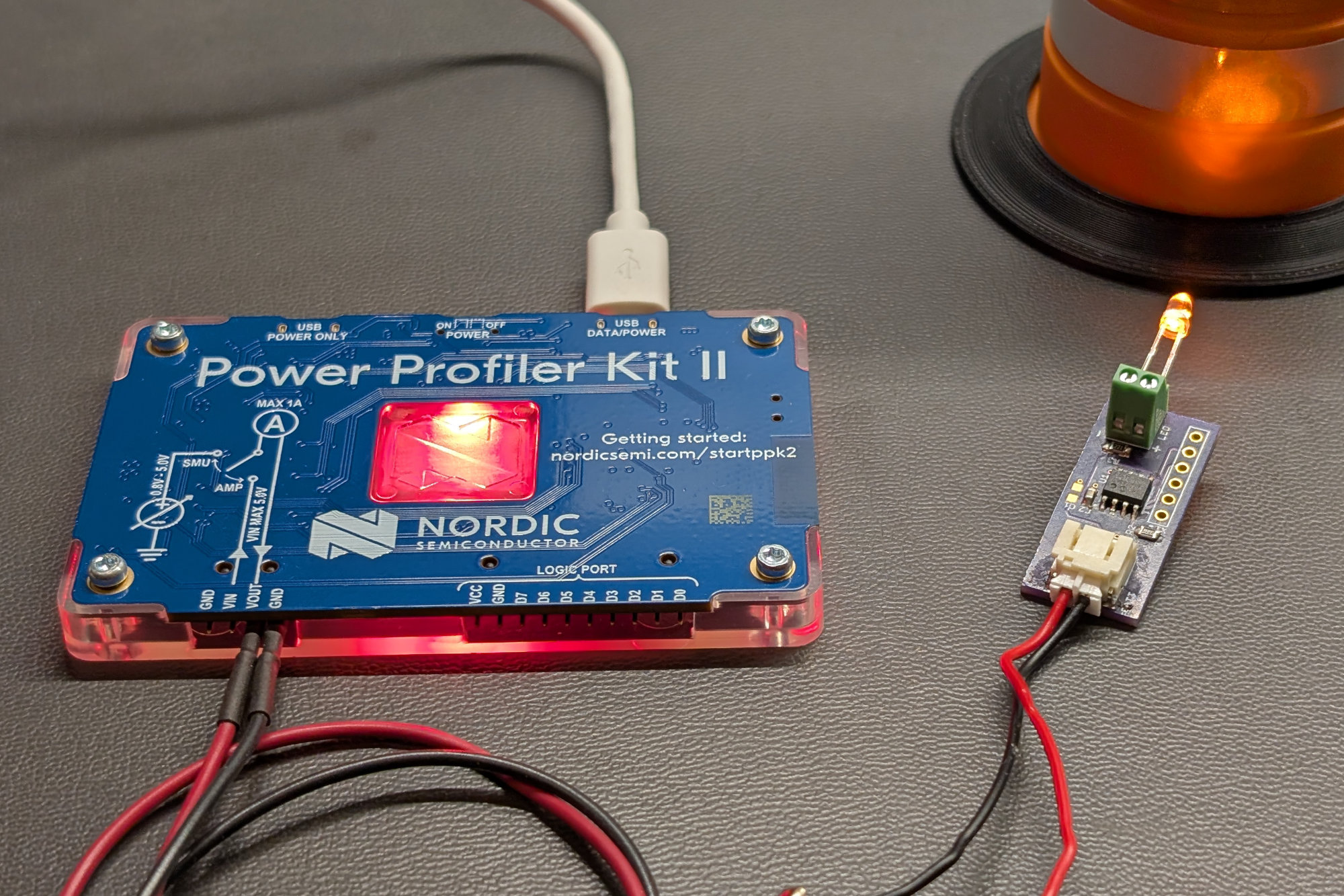
The Nordic PPK II is great for measuring current and estimating battery lifetime.
To calculate the estimated battery life, we’ll estimate the project’s current consumption then calculate the battery life from the specified battery’s capacity and the current estimate. We’ll also use the Nordic Power Profiler II pictured above to take measurements then compare those measurements to our estimates.
We’ll use these numbers for our calculations:
- The nominal voltage for a single-cell LiPo battery during most of its discharge curve is 3.7 V.
- The LiPo battery has a 110 mAh capacity and 85 % of that capacity is available before the battery is discharged enough for the the protection circuit to kick in.
- The red LED has a forward voltage of 2.0 V.
- The red LED’s current limiting resistor is 220 Ω.
- The red LED’s duty cycle is 10 %.
- The microcontroller consumes 18 µA (read from the graph in datasheet).
First, calculate the average current consumption of the LED at 10 % duty cycle:
- (3.7 V – 2.0 V) / 220 ohm * 10 % = 773 µA
Add the current from the microcontroller to get the average combined current:
- 773 µA + 18 µA = 791 µA
Available battery capacity:
- 110 mAh * 85 % = 93.5 mAh
Calculate run time in hours:
- 93.5 mAh / 791 µA = 118 hours
That’s almost five days from the small LiPo battery pack!
Average Current at 4.2 Volts
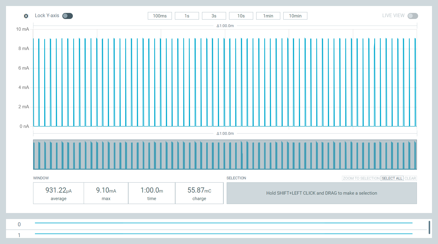
One minute current consumption at 4200 mV.
Now we’ll measure the current consumption using the Nordic Power Profiler. We’ll perform the first measurement at 4.2 V. This is the voltage from a freshly charged LiPo and represents our worst case LED current. After running for a minute, the average current is 931.22 µA. At 85 % of 110 mAh, this would be a battery life of 100 hours. Each ~9 mA spike in current in the graph above is the LED current at a 10 % duty cycle.
Average Current at 3.7 Volts
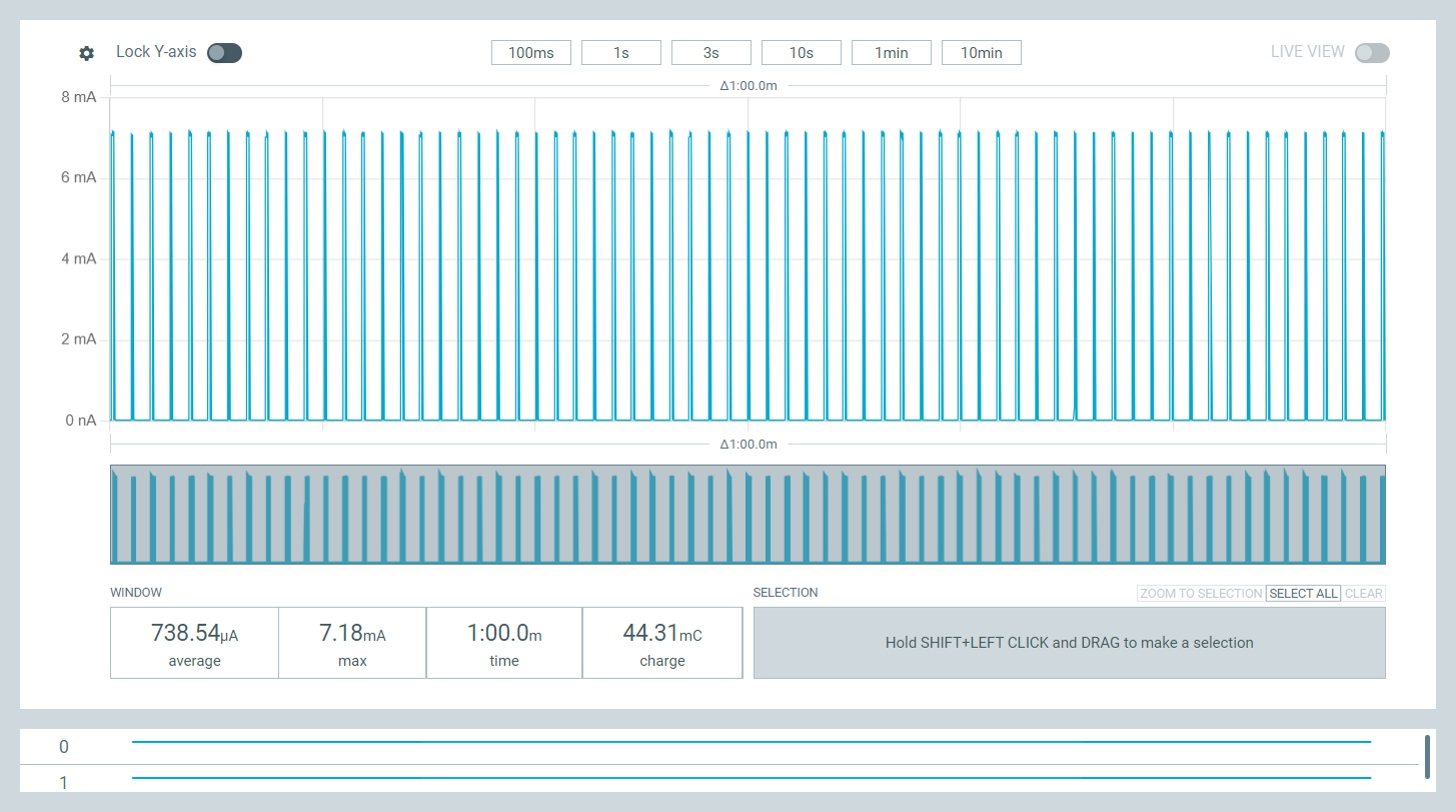
One minute current consumption at 3700 mV.
A LiPo cell doesn’t spend much time at 4.2 V before discharging to its nominal output voltage of 3.7 V so we’ll repeat these measurements at 3.7 V. After running for a minute, the average current is 738.54 µA. At 85 % of 110 mAh, this would be a battery life of almost 127 hours. Based on this measurement and the previous measurement at 4.2 V, we can reasonably assume that the battery life will be on the order of 4 to 5 days!
Microcontroller Current
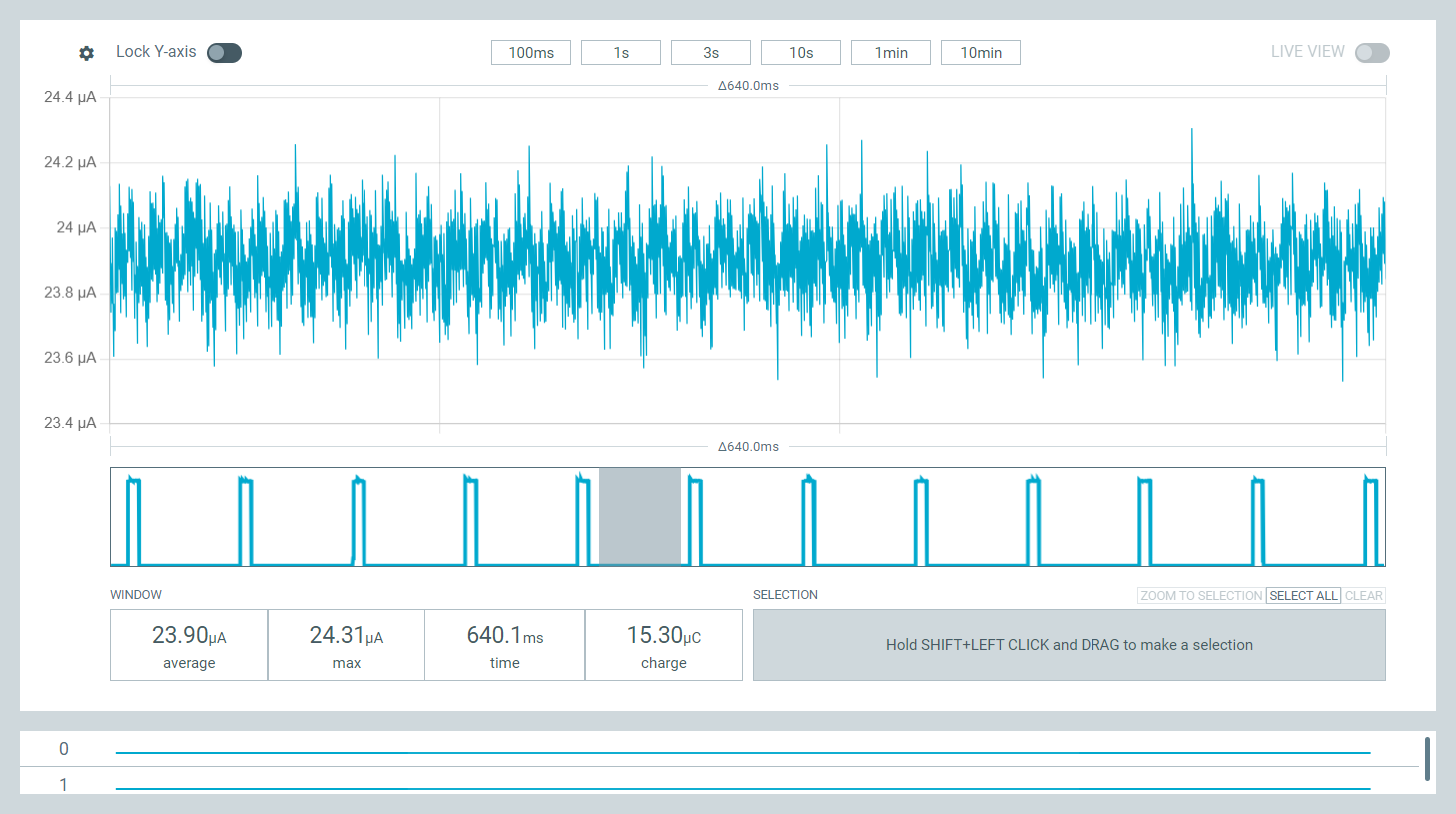
The PIC12’s power between the LED’s flashes.
Next up, we’ll zoom in on the power consumption at 3.7 V between flashes of the LED. The microcontroller is pulling about 24 µA running from its 31 kHz oscillator.
Depending on the manufacturer and specific variant, this is about 1/6 the current consumption of a CMOS 555 timer like TI’s LMC555 at 150 µA. It’s not a lot compared to the LED but using a CMOS 555 timer would still reduce the battery life of the project by about 15 % compared to using the PIC12 microcontroller:
- 739 µA + an additional 125 µA = 864 µA, 110 mAh * 85 % / 864 µA = 108 hours.
- (108 hours – 127 hours) / 127 hours = -15 %
Not to mention losing the flexibility to adjust the flash rate, duty cycle, and pattern via a software change.
The PIC12’s measured 24 µA is quite a bit lower than the 45 µA at 3.0 V specified in the PIC12’s datasheet:
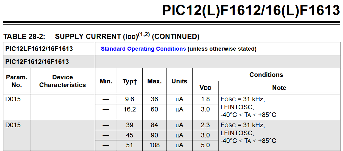
Supply current table from the PIC12F1612 datasheet.
The PIC12’s measured 24 µA is also a bit higher than the 18 µA at 3.7 V specified in the graph in the PIC12’s datasheet:
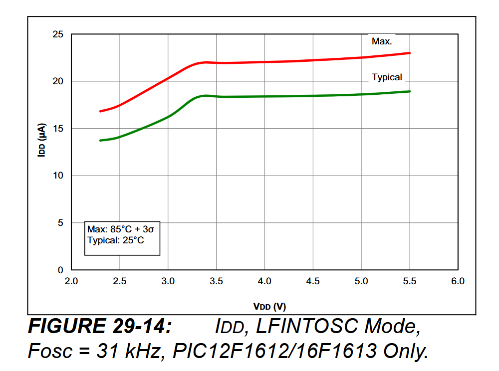
Supply current graph from the PIC12F1612 datasheet.
Someday, I might dig further into the discrepancy but I’m happy with PIC12’s current consumption and the overall battery life of the project.
In The Real World
I let one of these lights blink on my kitchen counter for a few days. I stopped after hitting 108 hours. That was sufficient to prove the battery life estimates and expectations were in the ballpark.
Simplifying the Electronics
After assembling three boards and three barrels, it was time to order a second set of boards. For this set of boards, I decided to skip the programming header and to eliminate most of the components I didn’t use on the original board.
Blinker Board Hardware Version 2
Schematic
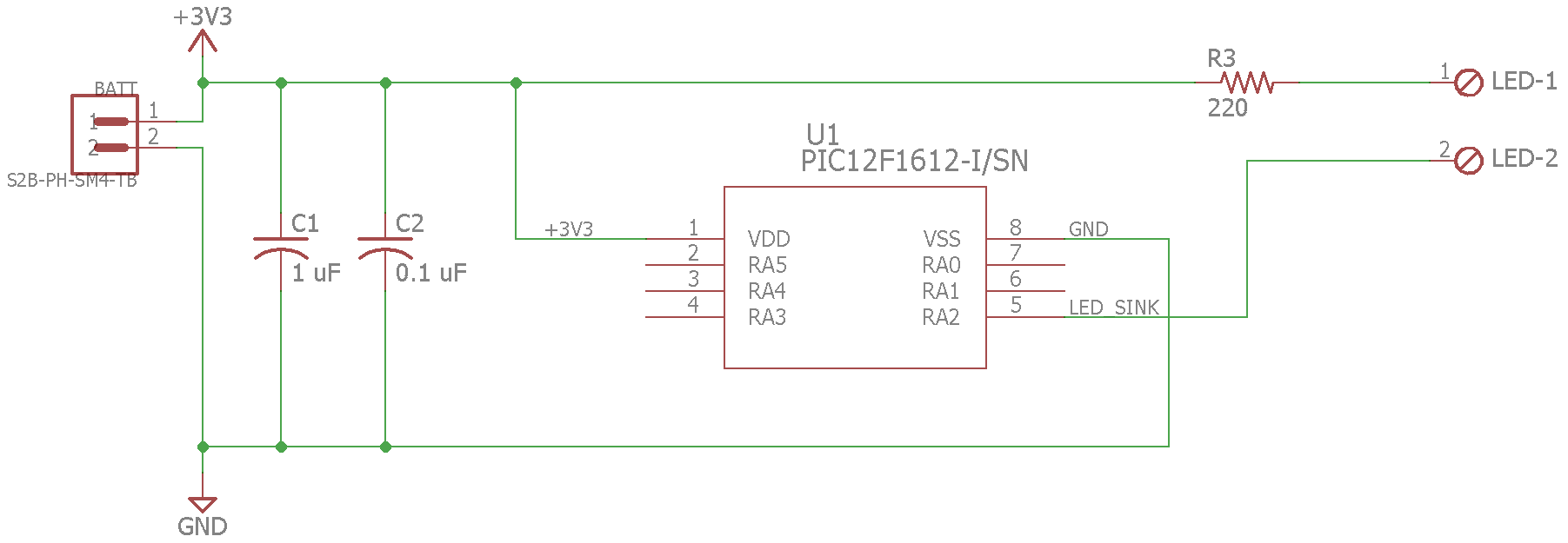
Simplified blinker board schematic.
The second version of the hardware has the connectors, the PIC12, and 3 passives. Of the three passives, only two are stuffed: the 0.1 µF decoupling cap and the LED’s current limiting resistor. When low-voltage programming is enabled, this version of the board relies on the PIC12’s internal weak pullup on its MCLR pin not to bounce in and out of reset. If this doesn’t work, I can disable low-voltage programming and configure the MCLR pin as a general-purpose input with a weak pullup instead.
Layout
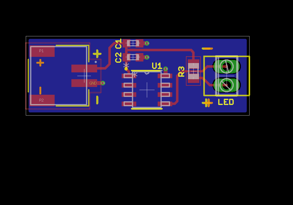
Simplified blinker board layout.
Simple layout.
Bill of Materials
The bill of materials is listed in the table below.
| Designator | Description |
|---|---|
| C1 | 1 uF 0603 (not used) |
| C2 | 0.1 uF 0603 |
| R3 | 220 0805 |
| U1 | Microchip PIC12F1612-I/SN |
| Battery Connector | S2B-PH-SM4-TB (JST PH 2 mm, 2 position) |
| Battery | Sparkfun PRT-13853 110 mAh Li-Ion Battery |
| LED Connector | Phoenix Contact 1725656 |
Notes:
- All capacitors are X5R or X7R and rated for at least 10 V.
- All resistors are rated for at least 1/10 W.
Assembled
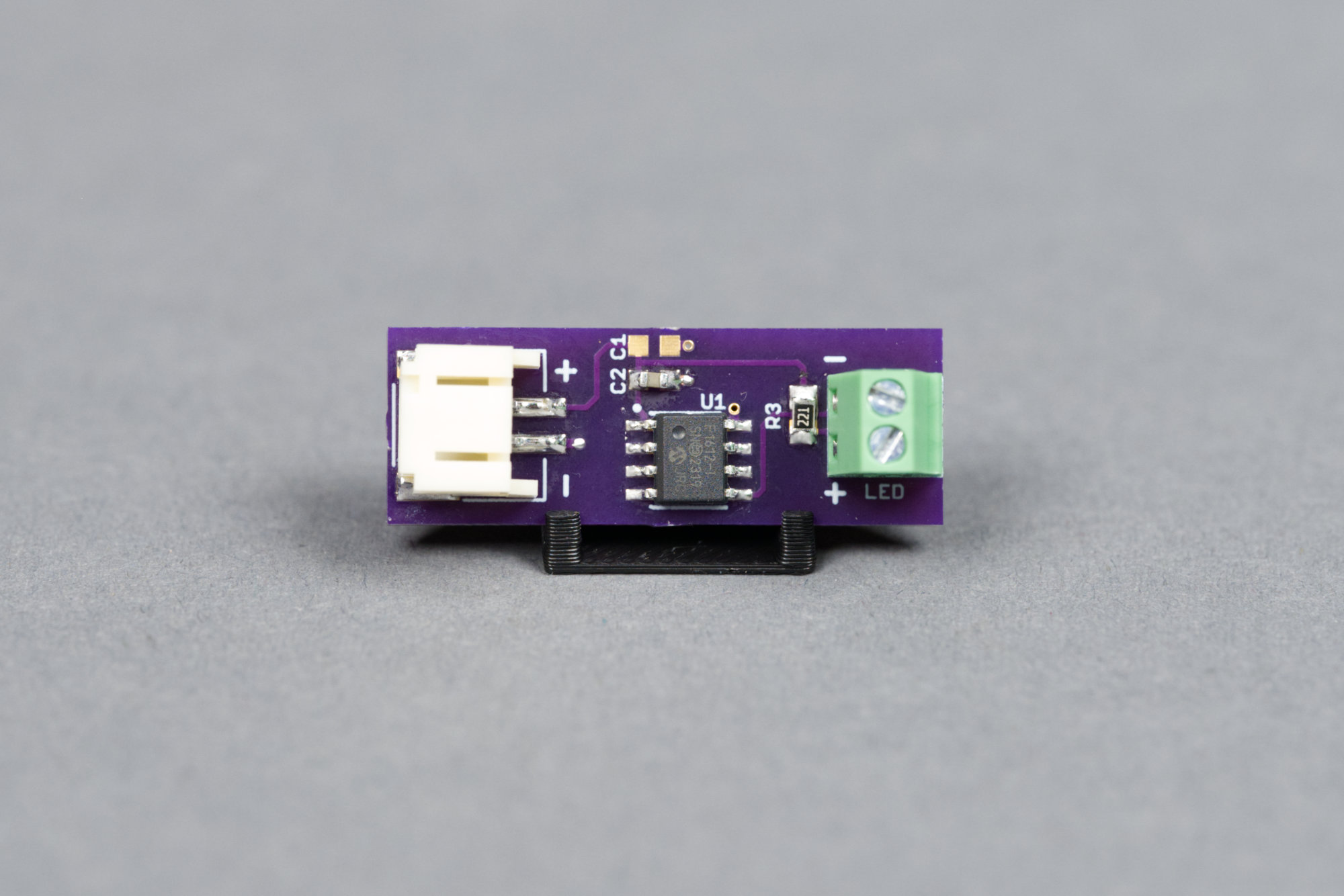
The simplified version of the board.
A photo of the assembled board is shown in the image above.
Programming Clip Adapter
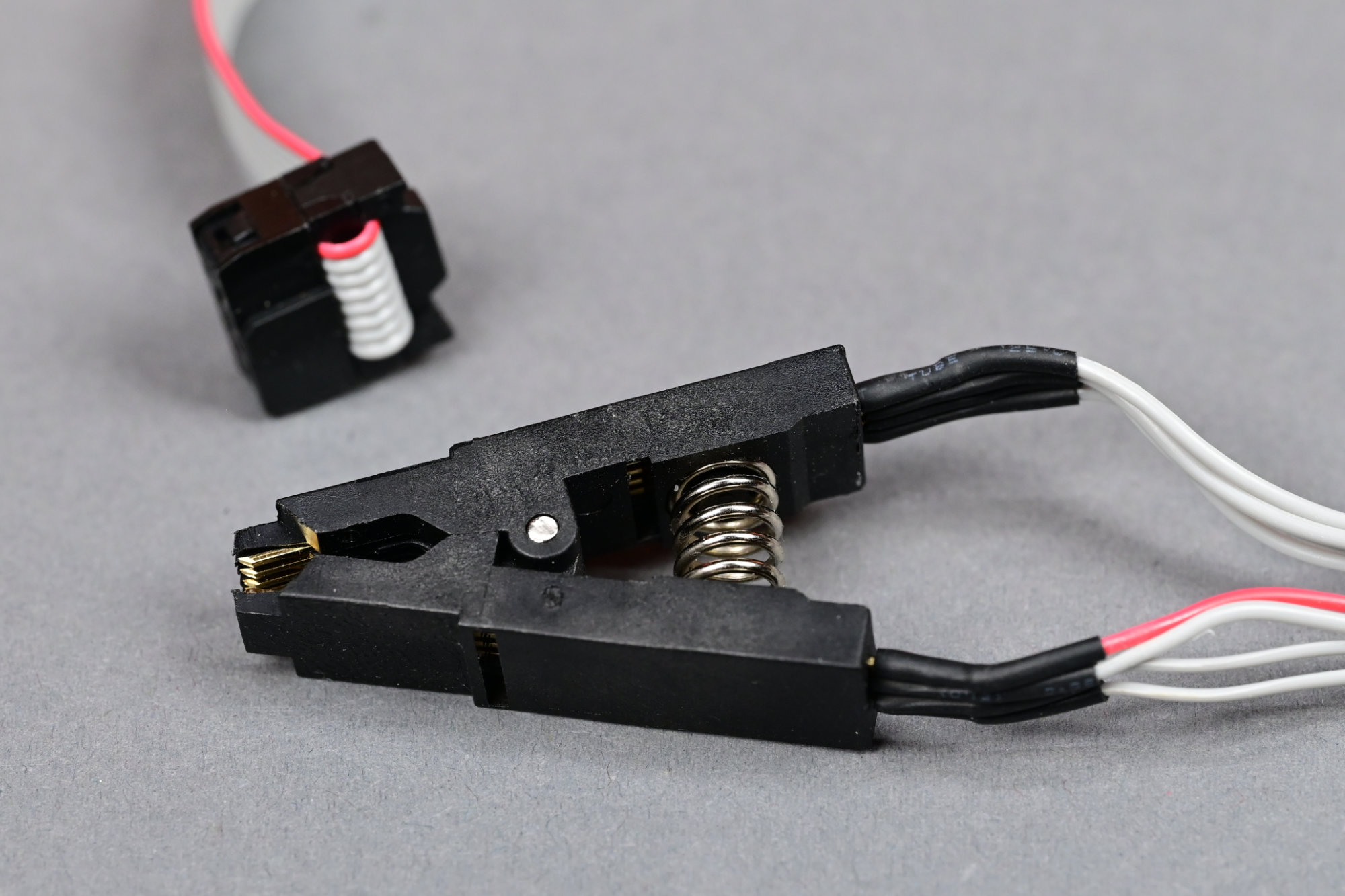
Generic SOIC-8 test clip purchased off Amazon. In theory, it’s for updating your PC’s BIOS.
Since there’s no programming header on the PCB, I’m going to use the SOIC-8 clip in the photo above to program the PIC12. The 2×4 header socket on one end will connect through an adapter to my PICkit 5 programmer / debugger. The clip end will clip on to the PIC12 on the assembled boards. I could also build a board with a SOIC-8 socket that connects to the PICkit 5 and program the parts before placing the PIC12 on the board. The clip is more convenient, especially if I want to change the software later or use the debugger.
Since I plan on using the PIC12 on future projects, I’m going to build an adapter board to connect the SOIC-8 clip to the PICkit 5. I could use jumper wires but that means reconnecting a mess of jumper wires every time I switch between different programming headers (SOIC-8 clip, Tag-Connect, 6-pin header, RJ-11, etc.)
Schematic
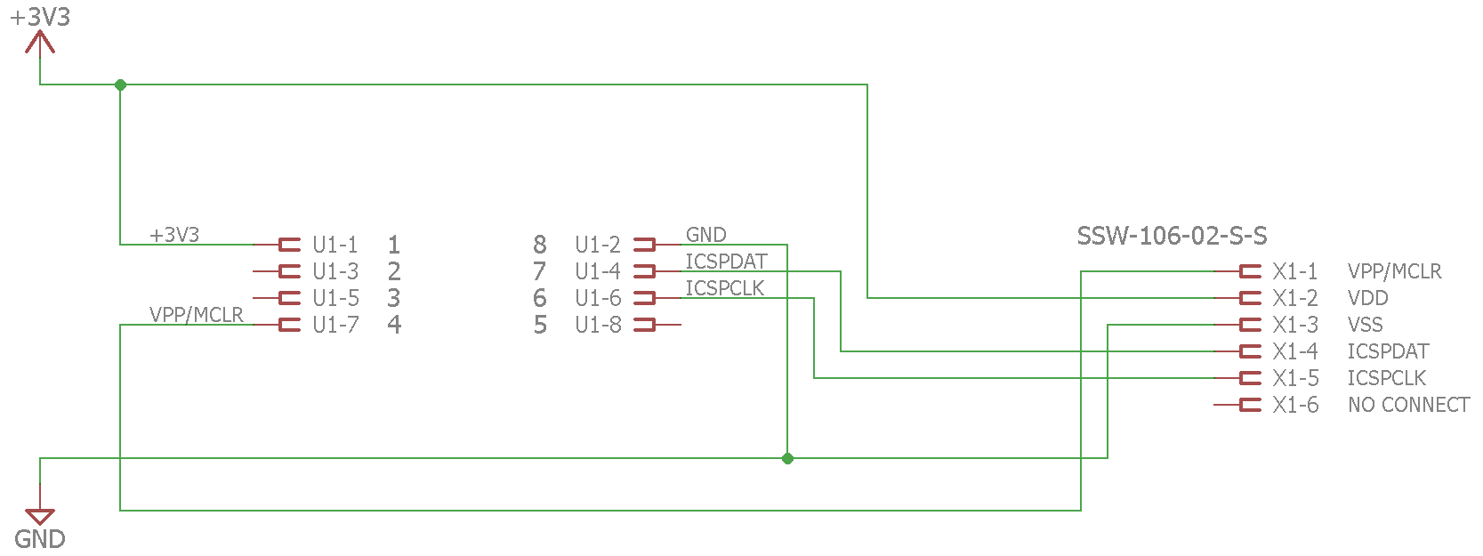
Programming adapter board schematic.
The schematic just connects a 2×4 header for the clip to a 1×6 header for the PICkit 5.
Layout
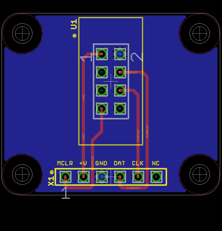
Programming adapter board layout.
The adapter board layout is shown above. It’s just two connectors and some holes for some standoffs.
Bill of Materials
The bill of materials for the adapter board is shown in the table below.
| Designator | Description |
|---|---|
| X1 | Samtec TSW-106-08-G-S-RA 6 position, 0.1″ right angle header |
| U1 | Würth Elektronik 61200821621 polarized shrouded header |
Assembled
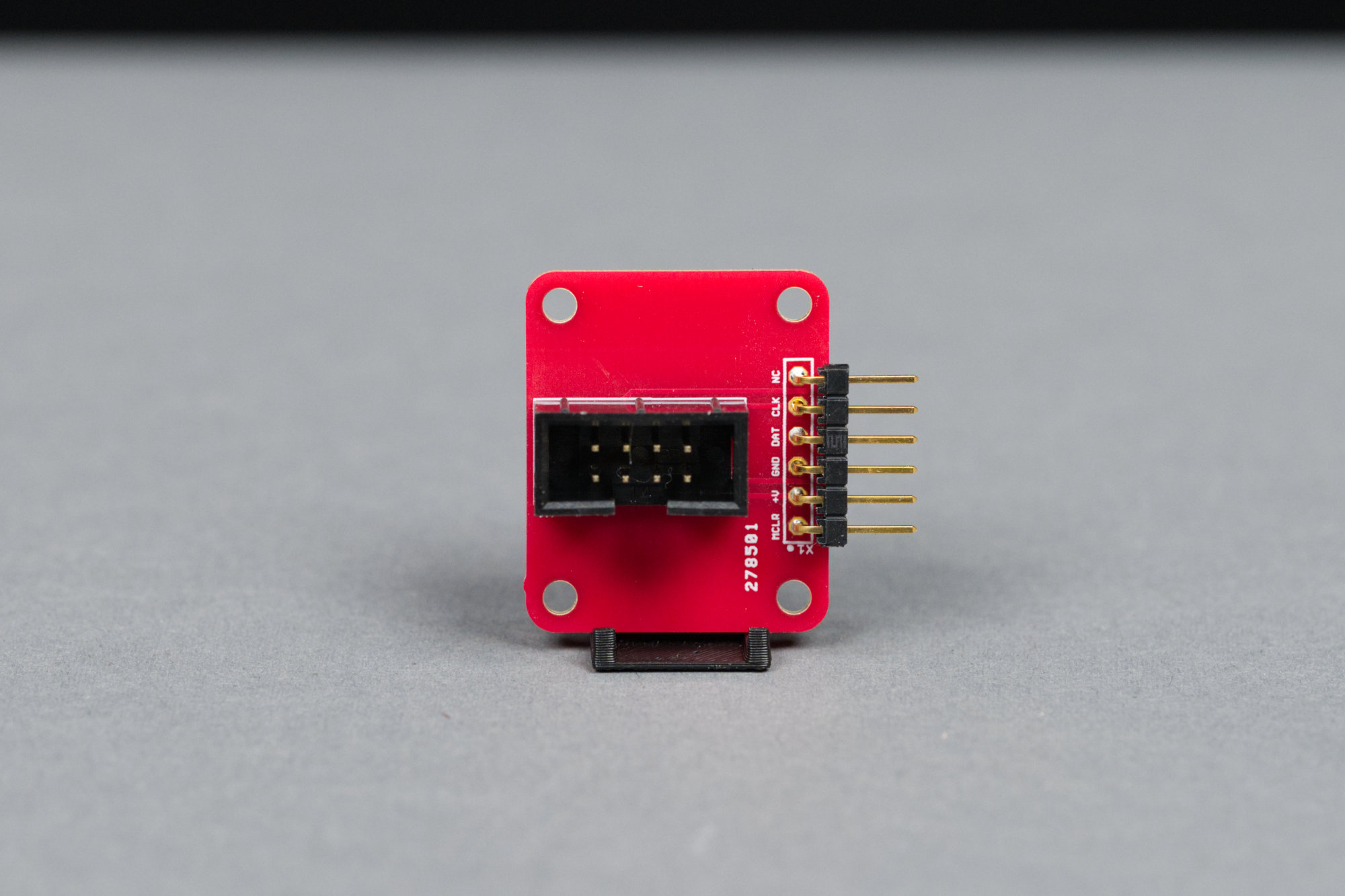
The assembled board. It’s pretty simple.
The assembled adapter board is shown in the photograph above.
Putting it All Together (Again)
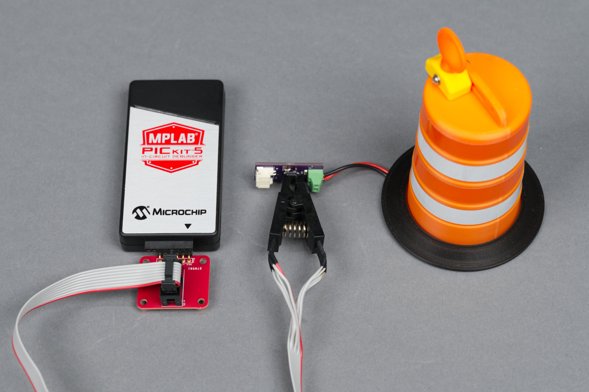
Programming the blinker board using the adapter board, clip, and PICkit 5. This photo is completely not staged. Not at all. Notice the USB cable missing from the programmer?
The photo above shows the clip attached to the PIC12 on the simplified board and the clip’s cable connected to the PICkit 5 programmer / debugger using the adapter board. This works for both programming and debugging the part (when the PICkit 5 is connected via USB to the host PC).
Conclusion
The completed set of traffic barrels.
One of the cool things (for this project anyway) about the PIC12’s built in 31 kHz oscillator is that it is not very accurate. This results in the barrels appearing to be in sequence one moment then looking out of sequence or in a different sequence the next moment—just like in a real life work zone.
Design Files
Coming Soon:
- Fusion Archive
- Barrel 3MF File
- Weighted Ring 3MF File
- Warning Light 3MF File
- Blinker Board v1 Eagle PCB Files, PDF Schematic, and Gerbers
- Blinker Board v2 Eagle PCB Files, PDF Schematic, and Gerbers
- Programming Adapter Eagle PCB Files, PDF Schematic, and Gerbers