
The single ESC key USB keyboard.
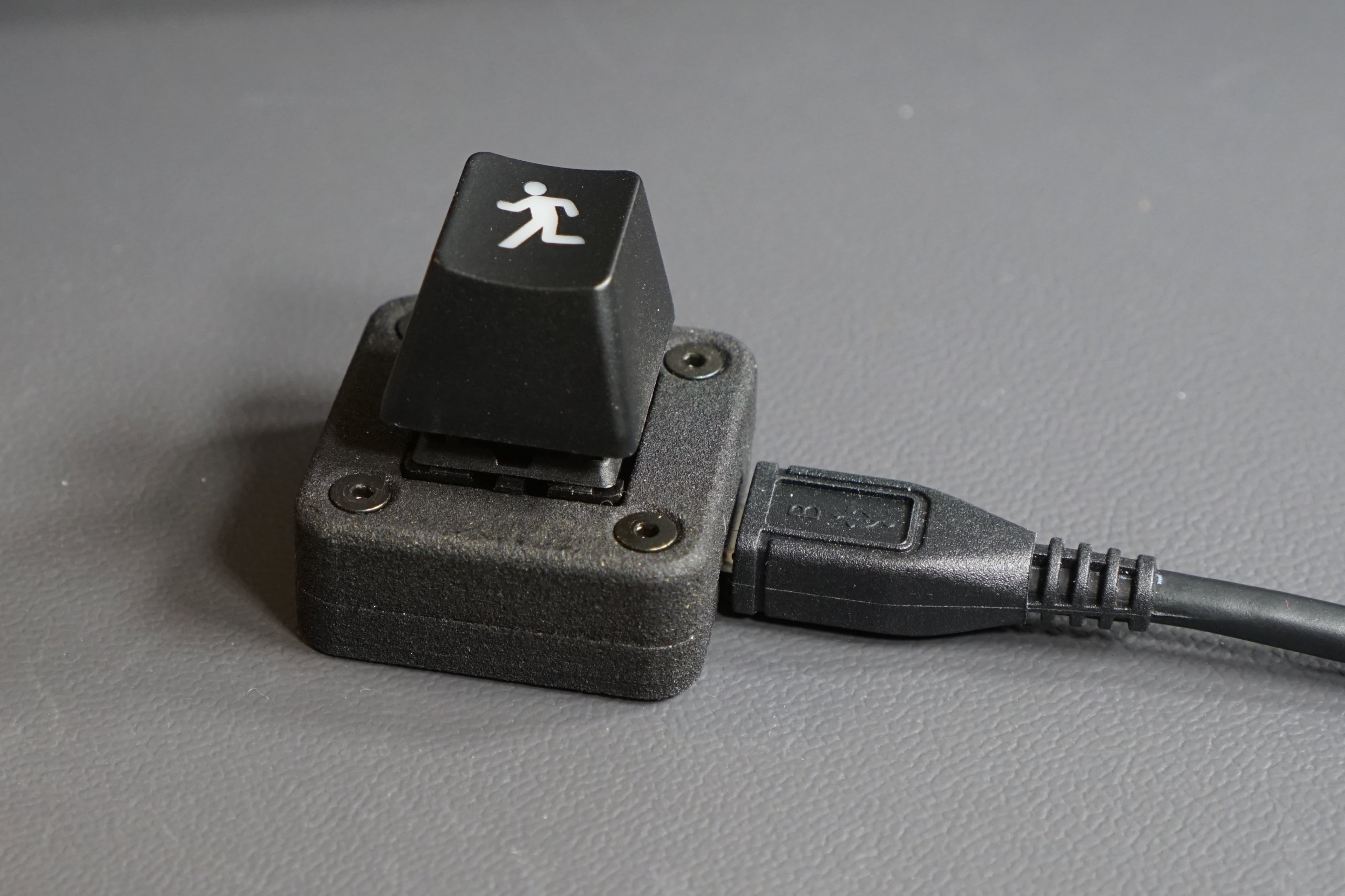
After building the “awesomely impractical” giant three-key keyboard, I decided it was time to build something a bit more practical—presenting the single ESC key USB keyboard! This keyboard has exactly one function which is to provide an optimal ESCing experience regardless of whatever keyboard you normally use. In exchange for giving up a USB port, you get a dedicated tactile, clicky Cherry MX blue ESC key.
The only possible target demographics for this keyboard are vi/vim users on touch strip MacBooks or those who like wasting USB ports on needless functions. On the slightly more practical side, there’s a three-key version too. With a bit of programming, these three keys can be assigned whatever functions are needed. On mine, the first key does CTRL-ALT-DEL, the second key locks the screen (META-L), and the third key is an escape key.

The three key USB keyboard. The LEDs underneath the keycaps are really only useful for debugging.
Goals
The only real goal with this keyboard was to see how small I could build a functional USB keyboard with a Cherry MX key switch. The keyboard needed to have an enclosure and the enclosure needed to be easy to assemble and disassemble which meant using screws to hold it together versus snapping together.
Selecting Parts
Picking a USB Microcontroller
I chose a PIC16F1459 in an SSOP-20 package for the microcontroller. The PIC16F145x family provides a minimal parts count solution to implementing the USB 2.0 standard. No external oscillator is required because this micro has an internal 48MHz oscillator and uses active clock tuning to fine-tune the internal oscillator frequency to the recovered clock from the USB host. This micro, a USB connector, and three capacitors are all that are needed to implement a fully-functional USB 2.0 device.
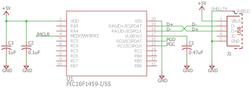
Minimal PIC16F1459 schematic for USB 2.0 operation.
Once I selected the microcontroller, I needed to pick a package for the microcontroller. The PIC16F1459 is available in DIP, SOIC, SSOP, and QFN packages. I chose the SSOP-20 package. The two larger packages were too big to fit in the allocated board space and the QFN package, though smaller, would be considerably more difficult to hand solder.
The USB Connector
Next up was to find a suitable USB Micro-B connector. Since the entire board was to be hand soldered, I wanted a connector with locating pins to position the connector on the board while I soldered it and with enough room between the connector housing and the five signals pins that I could easily see what I was doing with a microscope. I ordered a bunch of USB Micro-B connectors, examined each of them, and finally found a Wurth Electronics connector that met my needs.
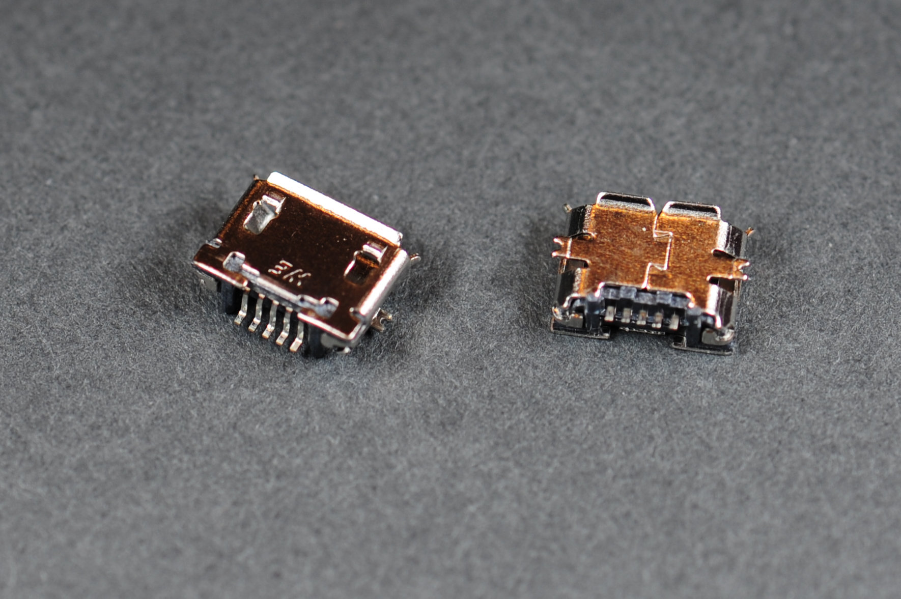
Wurth Electronics USB Micro-B Receptacle part number 629105136821. It has little black plastic posts to keep the connector centered while soldering and plenty of room between the shell and pins for the soldering iron, flux, solder, and inevitably, wick.
The Other Electrical Components
The rest of the electrical components weren’t super critical—a 0.47uF capacitor on the VUSB pin, a 0.1uF capacitor on the VDD pin, 1uF of bulk capacitance on the board, an LED, and a resistor. I used 1206 packages for the caps and resistor and a 3528 package for the LED because these were parts I had on hand.
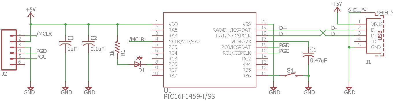
Complete one key USB keyboard schematic.
The PCB
Cherry MX key switches nominally occupy a 3/4” by 3/4” square area on the PCB. I decided to try to make the PCB 1” by 1”. It would have to be double sided with the key switch and LED on one side and the rest of the components on the other.
I drew a 1” x 1” board outline with 0.05” radius corners then placed a 0.1” diameter hole in each of the four corners. The holes are 0.1” from the edges of the board. I also tried to keep a 0.2” square keep out in each corner, but I ended up putting one cap, C2, a bit closer to the hole than I should have. The board turned out fine, but it significantly complicated the design of the enclosure. More on that later.
I found Eagle PCB libraries for the PIC, the USB connector, and the Cherry MX key switch. Links to these are in the Useful Resources section at the end of the blog post. I placed these components, wired everything up, made the gerbers, and ordered boards.
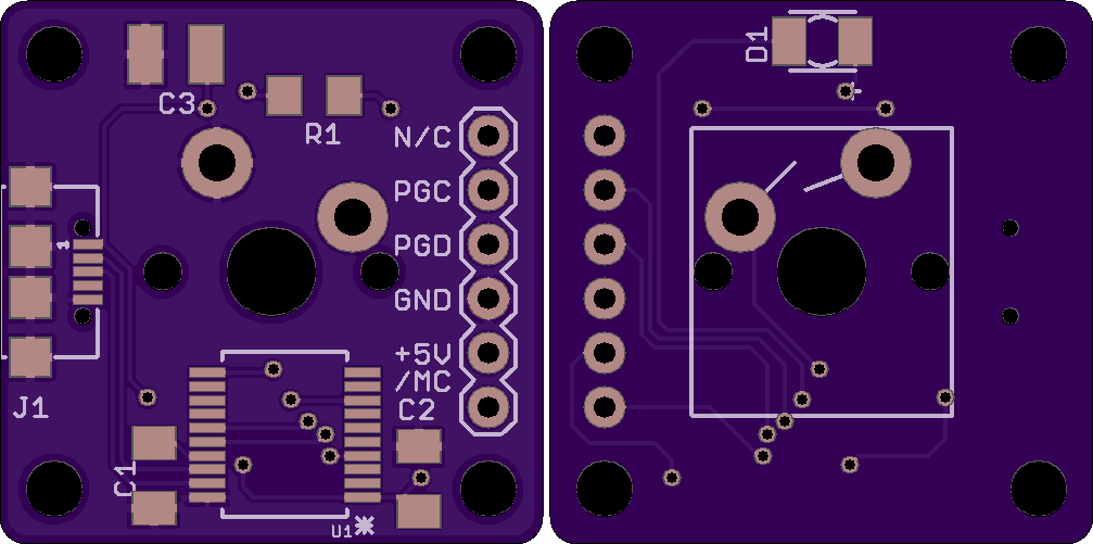
One key USB right keyboard PCB top and bottom views.
The Enclosure
While the boards were being manufactured, I turned to the design of the enclosure.
PCB 3D Model
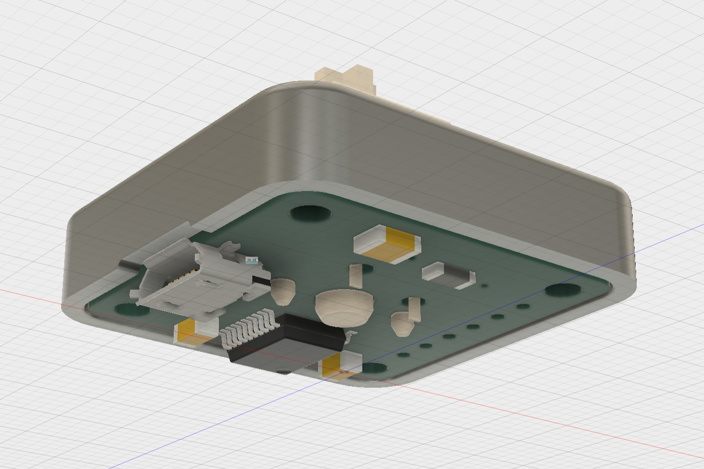
The first step was to use ecad.io to turn my PCB design into a 3D model that I could use to test the fit of the enclosure.
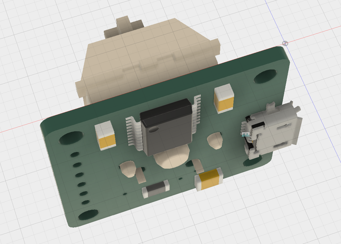
3D model of the PCB.
Critical Dimensions
The second step was to gather a list of critical dimensions. These are based on past experience and reading specs:
- Wall thickness: 1.5mm.
- Space between PCB edges and walls: 0.5mm.
- Board thickness: 1.6mm but allow 1.65mm.
- 2-56 screw free fit hole diameter: 2.54mm.
- 2-56 screw countersink diameter and angle: 5.30mm and 82 degrees.
- 2-56 nut cavity: 5mm across flats, 2mm deep.
- Maximum USB Micro-B overmold dimensions: 10.6 by 8.5mm.
- Minimum USB Micro-B mated clearance: 1.3mm
- 3D printer minimum wall thickness: 0.6mm, ideally 1mm.
Enclosure Bottom
I started with the enclosure bottom. The PCB is 25.4mm x 25.4mm so the enclosure needed to be 29.4mm x 29.4mm to allow for the 1.5mm wall thickness and 0.5mm space around the board edges. I added screw holes and recesses for the nuts on underside of the bottom of the enclosure.
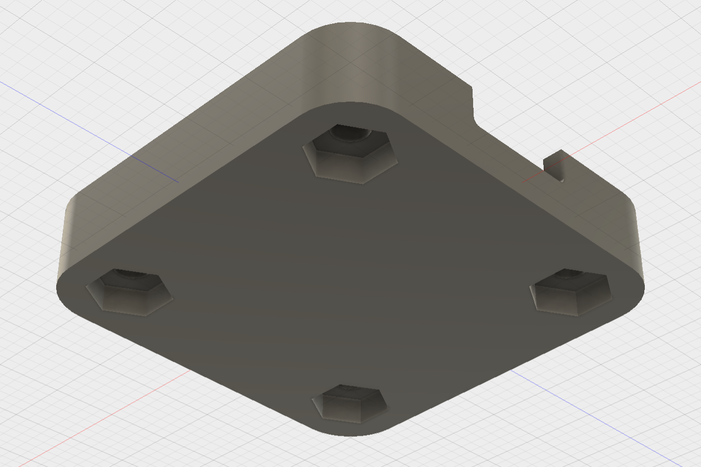
Enclosure bottom (exterior view).
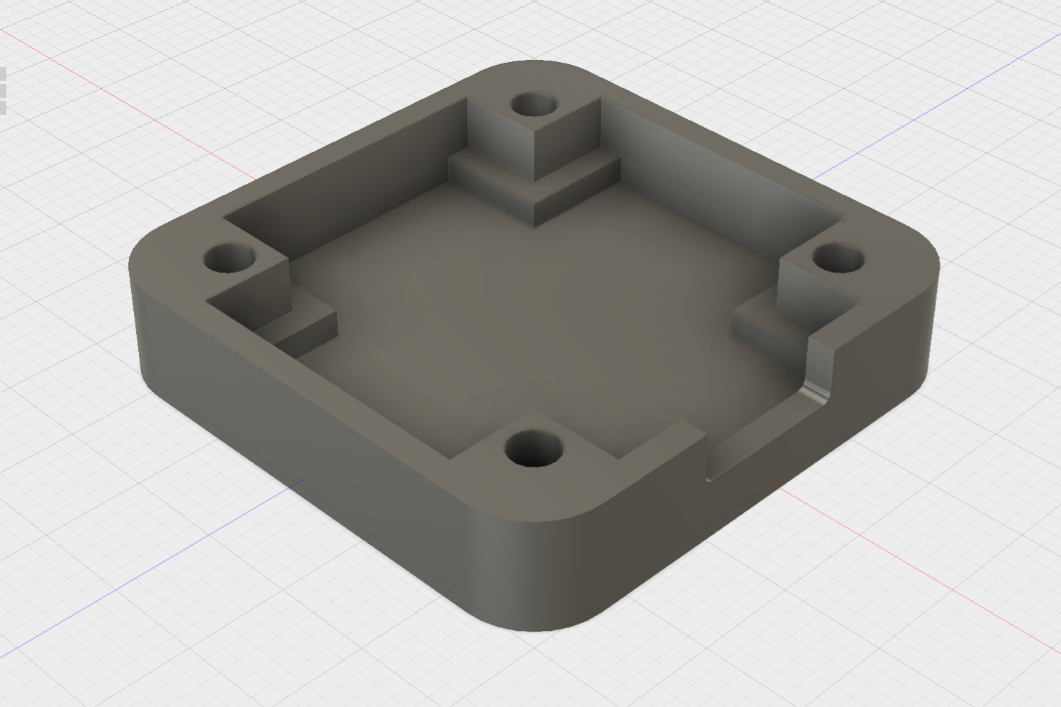
Enclosure bottom (interior view).
Here I hit the first snag. I needed at least 0.6mm and, ideally, 1mm of material around the top and sides of the hex nut recesses on the bottom of the enclosure to meet my 3D printer’s minimum wall specs. If I added this material all the way to the top of the enclosure, it would have necessitated a 6mm square keepout area in each corner of the PCB. Unfortunately capacitor C2 was already in this keepout area (see illustration below).
Since C2 was in the way, I only brought the material up 1.5 mm from the interior of the enclosure (which is 3mm from the exterior of the enclosure). This left a 1mm wall between the top of the nut recess and the interior of the enclosure. This was was within specs for printing and provided plenty of clearance for C2. Problem solved but next time I would have tried to move the capacitor over a bit on the PCB!
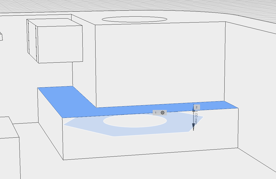
C2 is in the upper left hand corner. Dark blue is a face of the 6mm x 6mm cube around the nut recess. Light blue is the nut recess. The arrow indicates the 1mm wall thickness between the cube face and nut recess.
The second snag involved the the overall height of the enclosure. Initially the bottom was 5mm high making the enclosure 11.65mm high overall. I planned on using 7/16″ screws to assemble the enclosure. Unfortunately, my 7/16” screws were 0.020” short and barely reached the nuts. Also, the maximum USB plug overmold thickness is 8.5mm so for thick USB plugs the keyboard could be resting on the bottom of the USB plug versus resting on its own bottom.
Increasing the bottom height to 6.05mm and the overall enclosure height to 12.7mm solved both these issues. First, I could use 0.5” screws to assemble everything which more than adequately reached the recessed nuts. Second, this increased the distance from the center of the USB receptacle to the bottom of the housing to 4.7mm which is greater than the 4.25mm required by the USB Micro-B max overmold dimension specification.
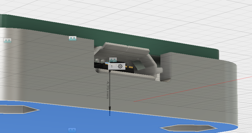
6.05 mm bottom height meets 4.25mm USB overmold clearance requirement.
The last critical dimension is the minimum mated clearance of a USB Micro-B receptacle and USB Micro-B plug. This dimension is listed as 1.3mm in the USB Micro-B connector specification. When a USB cable is plugged into the connector on the USB keyboard, they need to be fully mated. In order to support this requirement, the distance from the exterior face of the enclosure to the metal guides on the USB receptacle needs to be less than 1.3mm. In my design, they’re 0.7mm which will work.
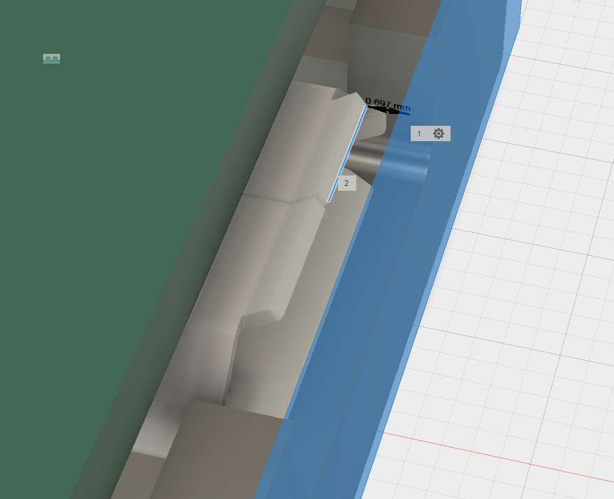
0.7mm clearance between receptacle guides and exterior face of enclosure.
Enclosure Top
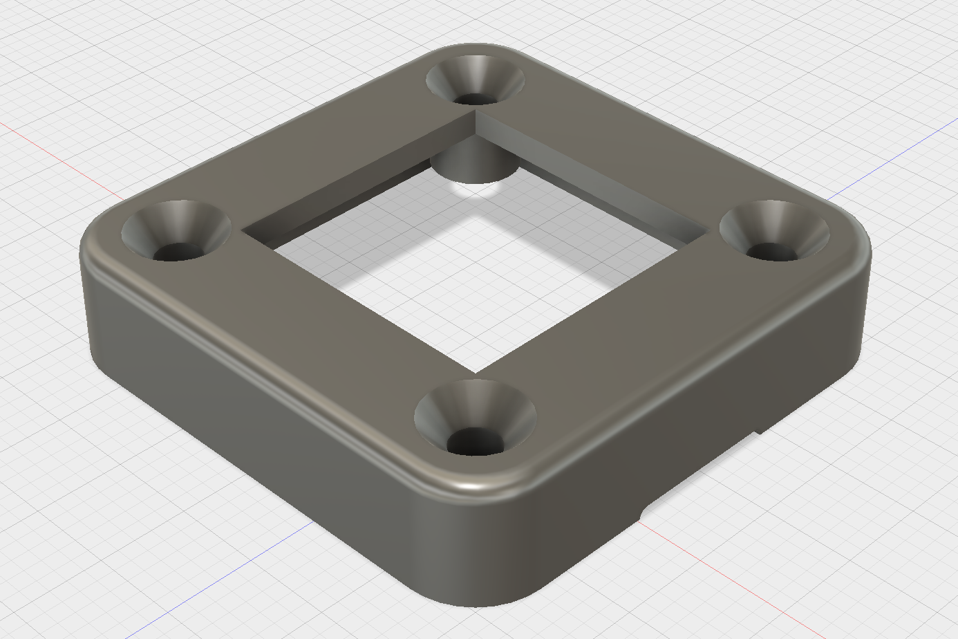
Enclosure top (exterior view).
Enclosure top (interior view).
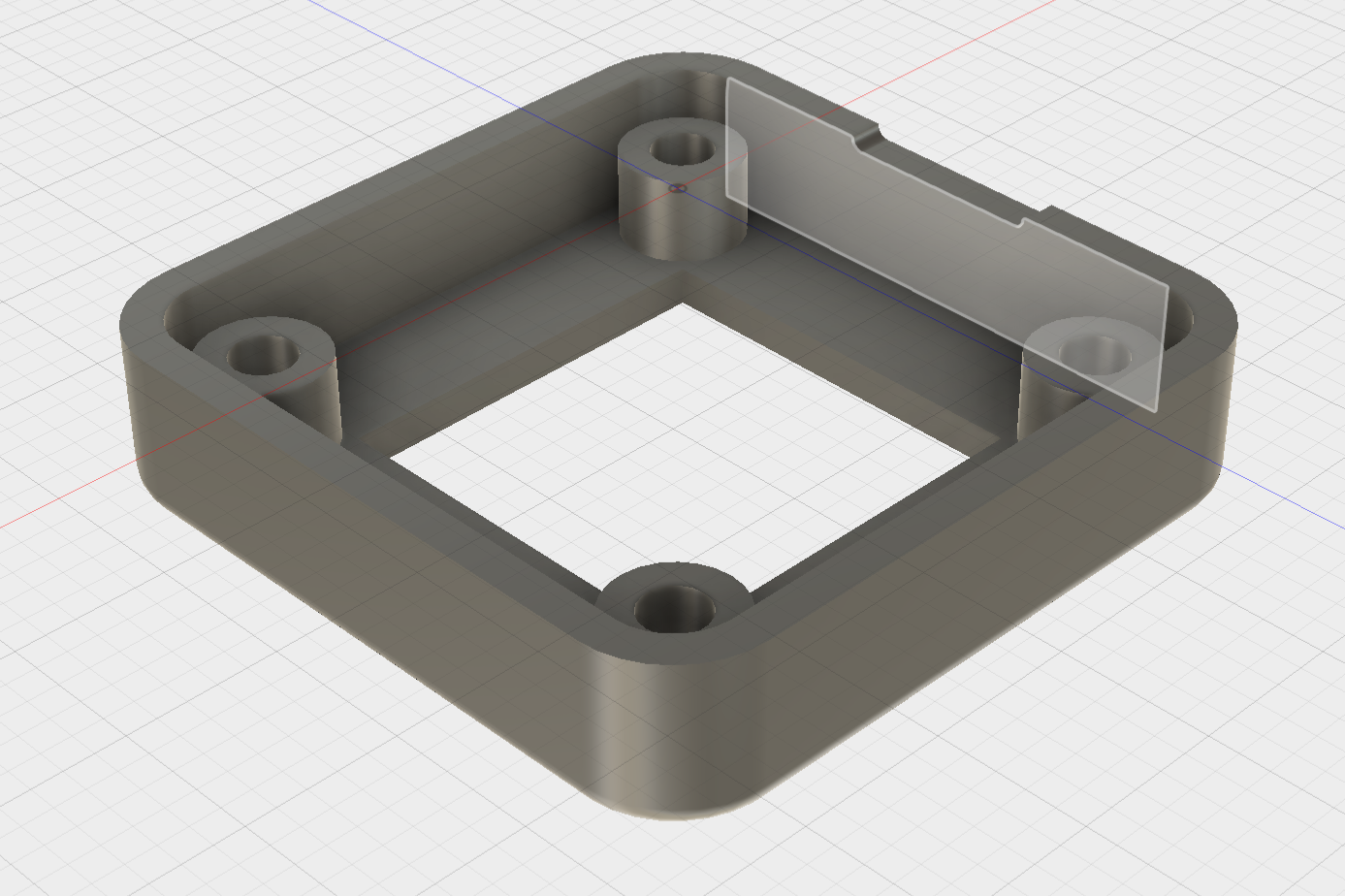
The enclosure top was significantly less challenging to design. The height needed to be the board height (1.65mm) plus the height to the bottom of the depressed key cap (about 5mm). I drew the exterior walls of the enclosure, added some cylinders around the screws, drew the countersink holes, cut out a square for the key switch, and added a bit of a notch around the USB connector. The cylinders are 1.65mm shorter than the enclosure so that the board fits completely recessed into the top of the enclosure.
PCB fits recessed into the bottom of the top half of the enclosure.
Manufacturing the Enclosure
I still don’t own a 3D printer. Instead, I opted to have my enclosures 3D printed at a service bureau on a selective laser sintering (SLS) 3D printer in black PA12 nylon. They turned out great. 3D prints on these machines are accurate and consistent from print to print.
Three Key Stretch
The three key version of the keyboard is a stretch of the one key version of the keyboard.
PCB
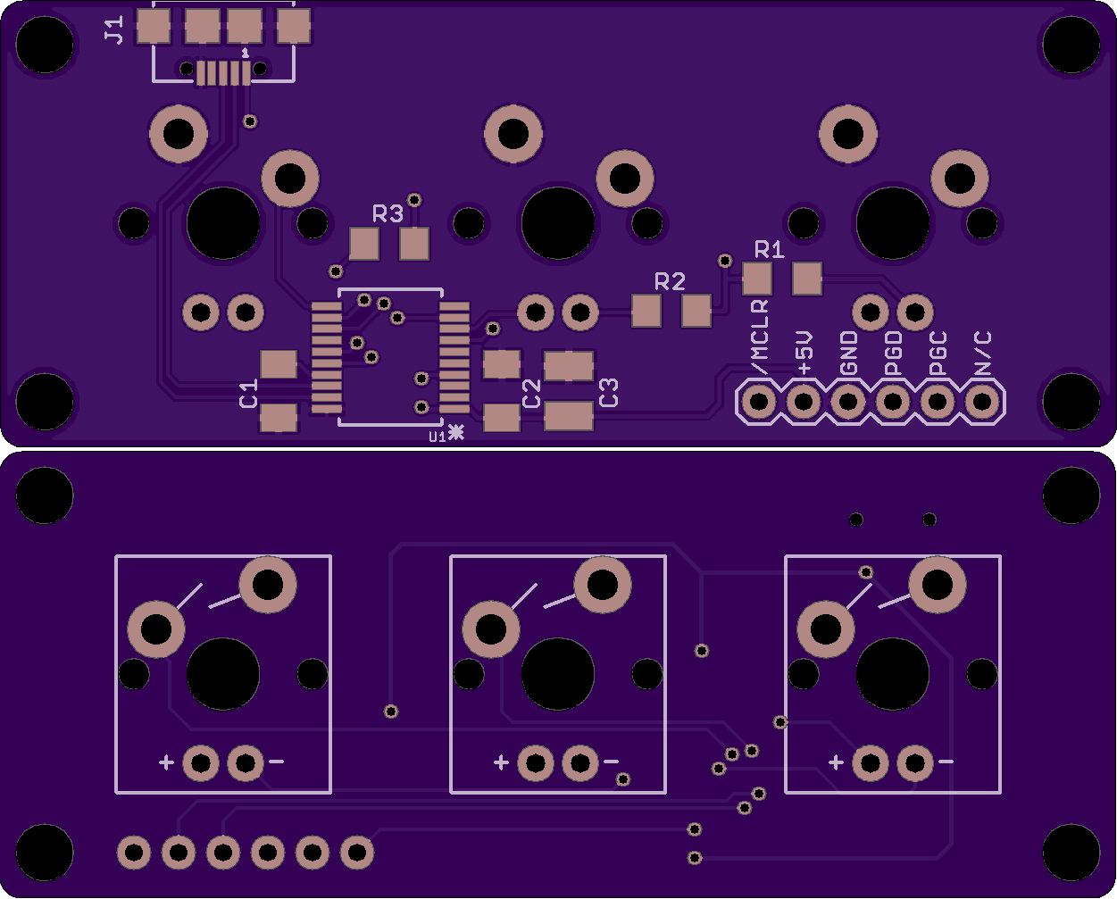
Three key USB keyboard PCB top and bottom views.
Enclosure
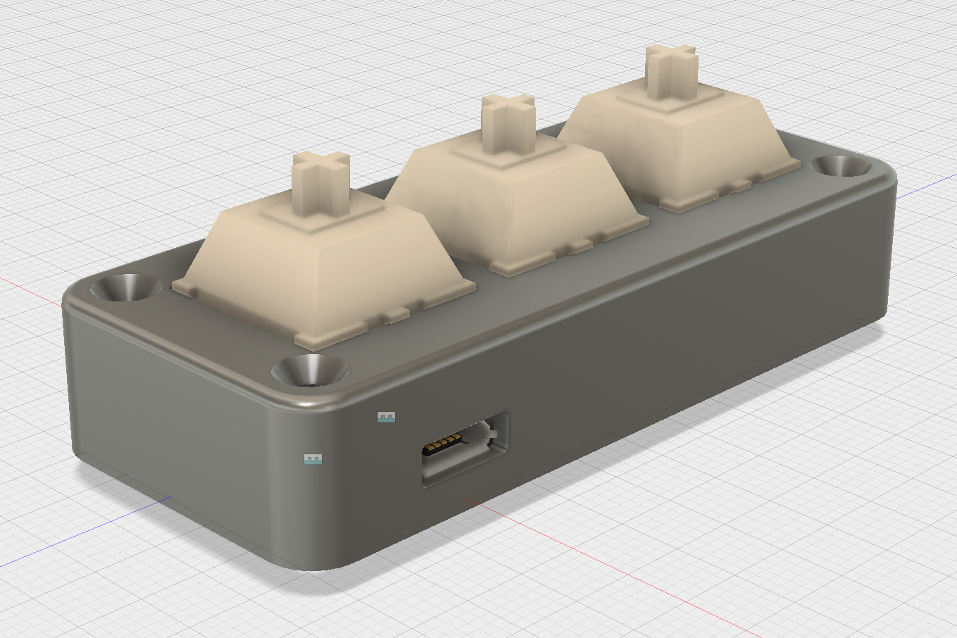
Rear view of the three key enclosure.
Building the Keyboard
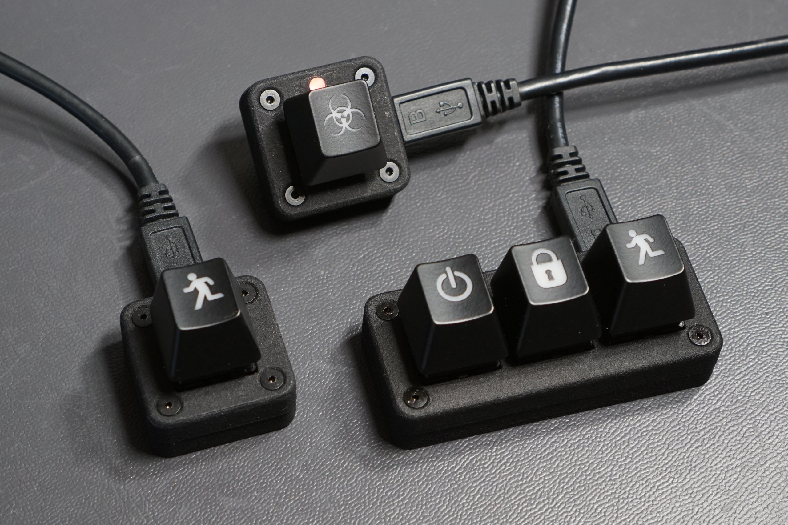
Three variations of the small USB keyboards: single key with USB top, single key with USB right and optional LED and light pipe, and finally the three key version.
The keyboard has three variations:
- Single key with USB top. There’s a hidden red LED on the right hand side of the key.
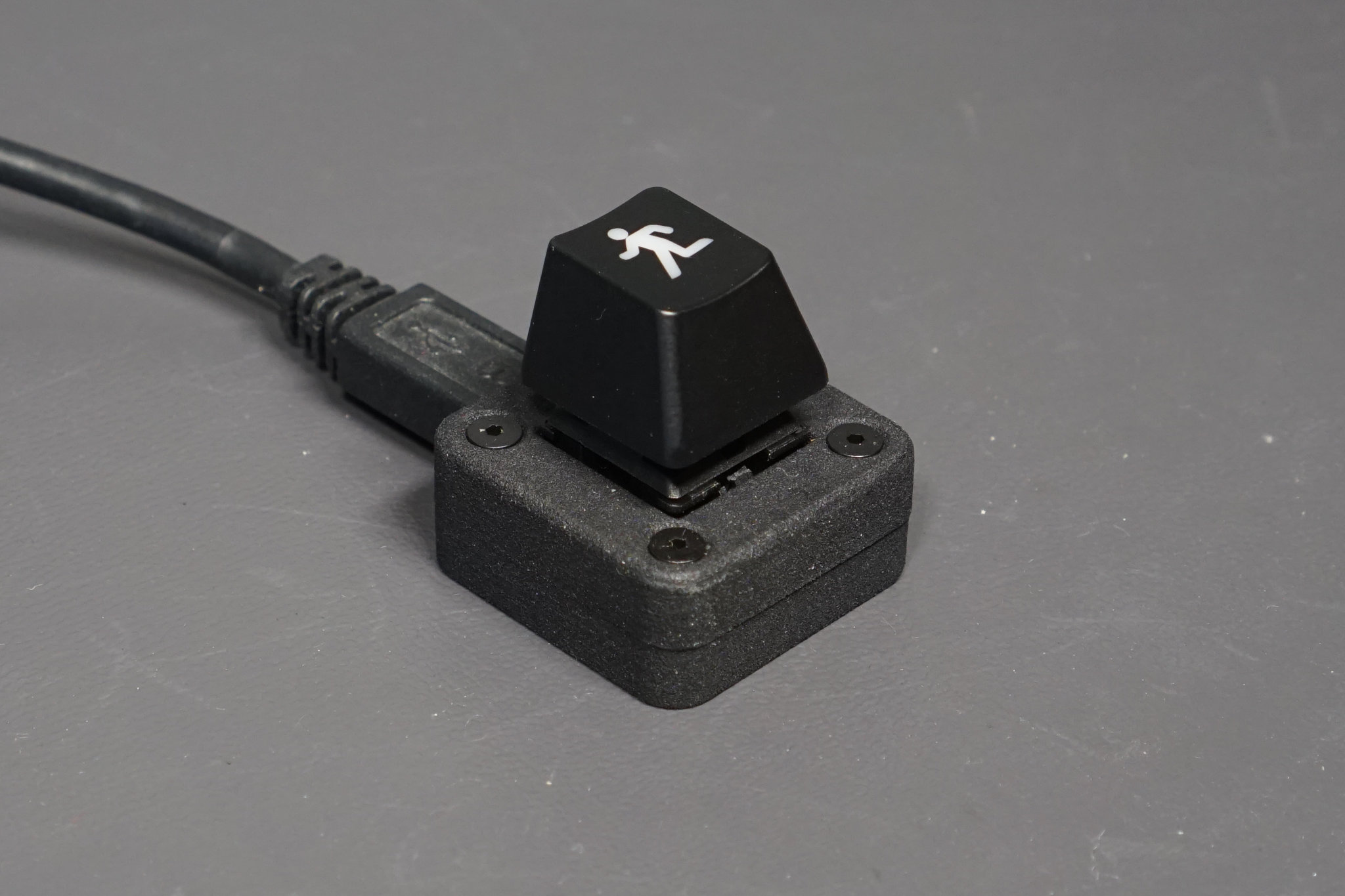
- Single key with USB right. There’s an LED on the top side of the key. Whether to expose the LED, keep the LED hidden, or use a light pipe to direct the LED light is up to you.
- Three key with USB top. This board has a provision for a 3MM through-hole LED under each key. These three LEDs really don’t add much to the project but having them to indicate the USB status is helpful when bringing up the board.
To build the keyboard, pick one of three basic variations then select the the PCB, enclosure, parts, and software for your board from the downloads section below. The one key USB right and one key USB top keyboards use the same 3D printed enclosure. To program the microcontroller, you need a PIC programmer such as a PICkit, ICD, or Real ICE.
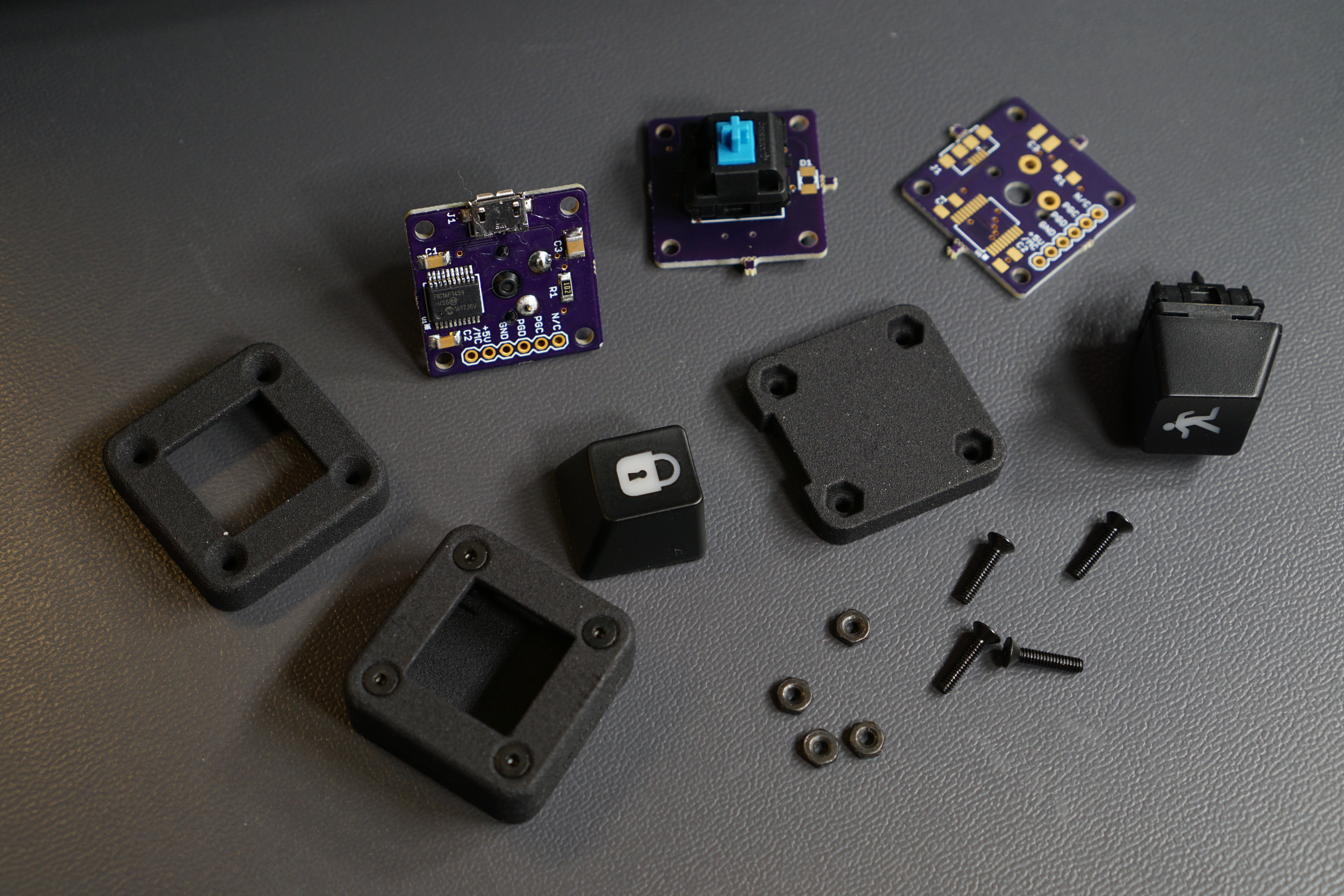
The parts and pieces required to build the single-key keyboard.
When assembling the PCB, I recommend soldering the USB connector first then soldering the PIC16F1459 next. After those two parts are soldered to the board, check the pins and traces for solder bridges very carefully then move on to soldering the rest of the surface mount components. Lastly, solder the Cherry MX key switch to the board. Do not solder a connector to the programming header on the PCB.
To program the micro, open the project in MPLAB X. Build the project. Connect the keyboard and programmer to USB ports on the PC. Finally program the micro while holding the programmer’s connector and a header in the holes of the programming of the header on the PCB.
When programming is complete, the red LED should flash quickly and the keyboard should begin working immediately. If it doesn’t, the most likely issue is solder bridges between the pins of the USB connector or PIC. To change what the key does, modify the key codes sent by the software on lines 359 to 372 of the function APP_KeyboardTasks in the file app_device_keyboard.c.
Once you’re happy with the operation of the keyboard, unplug it and assemble the case around the PCB. Finally, select a key cap and place the key cap on the key switch.
More Photos
Here are a few more photos.
One key with USB top.
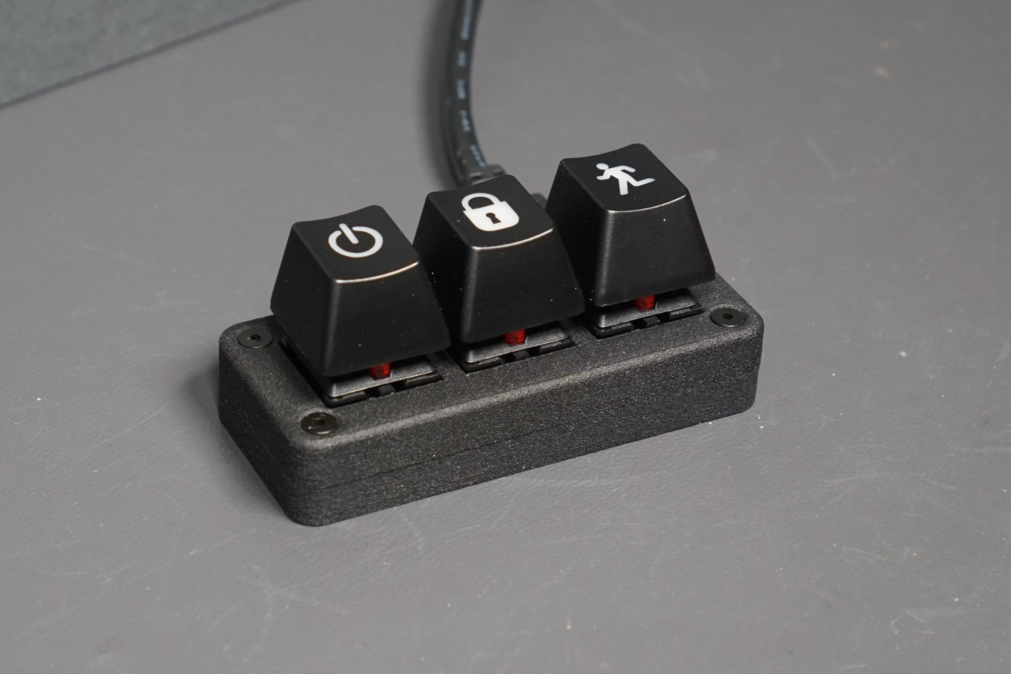
Three key.
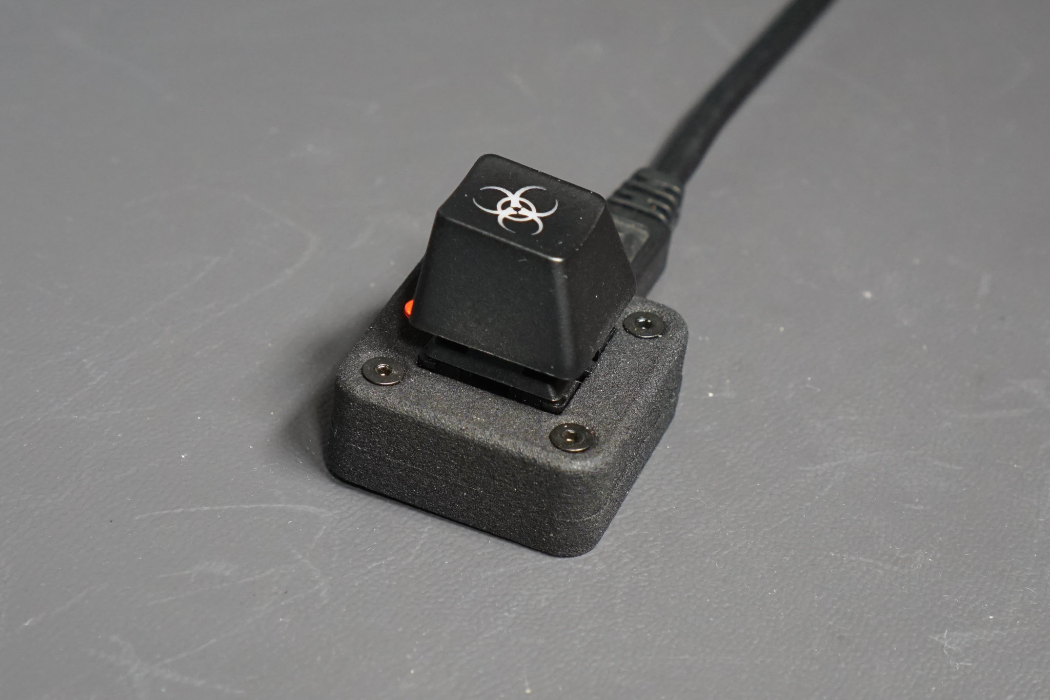
One key USB right with optional LED and light pipe.
Have fun! I hope you enjoyed this project!
Downloads
PCB
Pick one of the following PCB designs depending on which version of the keyboard you’d like to make. These link to directories on github containing both Eagle PCB files for modifying and Gerbers for manufacturing:
- Single key version with USB port on the right side
- Single key version with USB port on the top
- Three key version with USB port on the top
Enclosure
Pick an enclosure to match the selected PCB. The single-key USB right and single-key USB top keyboards both use the same single-key enclosure. These link to directories on github containing both STEP files for modifying and STL files for printing:
- Single key version for use with 2-56 x 1/2” screws
- Single key version for use with 2-56 x 7/16” screws (not recommended, see note below)
- Three key version for use with 2-56 x 1/2” screws
Note: the 7/16″ screws I ordered from McMaster-Carr were approximately 0.020” short of 7/16”. They worked but it took some finagling to get the screw threads to catch the nuts. For this reason, I’d recommend the 1/2” version of the enclosure. Also 2-56 x 1/2” screws are much more common, easier to find, and less expensive than 2-56 x 7/16” screws.
Software
Pick a software version. All software versions support from one to three keys. The default configuration is for key 1 to type an a, key 2 to type a b, and key 3 to type a c. The Non-USB bootloader version is the easiest to work with but it gets old disassembling and re-assembling the keyboard to update the firmware. If you select the USB bootloader version, you will also need the USB bootloader and the Microchip USB hex bootloader app.
These link to directories on github containing both the MPLAB X projects and pre-built .hex files that may be directly programmed into the part without opening or building the projects:
- Non-USB bootloader version. Requires disassembling keyboard to update firmware.
- USB bootloader version. After bootloader is programmed, firmware may be updated over USB without disassembling keyboard.
- USB bootloader. Bootloader for the USB bootloader version of the keyboard software.
If you selected the USB bootloader version, you’ll also need the Microchip USB hex bootloader app. This app is distributed as part of the Microchip Library for Applications (MLA) and may be downloaded here.
Bill of Materials
Electrical Parts
Part numbers in parenthesis are Digi-Key part numbers. Part numbers in brackets are Mouser part numbers.
- N=1 PIC16F1459-I/SS USB microcontroller. Microchip part # PIC16F1459-I/SS (PIC16F1459-I/SS-ND)
- N=1 USB Micro-B PCB mount jack. Wurth part # 629105136821 (732-3155-1-ND)
- N=1 0.47µF 50V 1206 capacitor. Similar capacitors with voltage ratings down to 16V may be substituted. Kemet # C1206C474K5RACTU (399-3498-1-ND)
- N=1 0.1µF 50V 1206 capacitor. Similar capacitors with voltage ratings down to 16V may be substituted. Kemet # C1206C104K5RAC7867 (399-1249-1-ND)
- N=1 1µF 16V 1206 capacitor. Similar capacitors may be substituted. Kemet # C1210C105K4PACTU [80-C1210C105K4P]
- N=1 or N=3 Cherry MX blue key switch or similar. Cherry # MX1A-E1NW (CH197-ND)
- N=1 or N=3 1kΩ 1206 resistors depending on if you selected the single key or three version of the keyboard. (optional, only needed if you add LEDs to your keyboard) Bourns # CR1206-JW-102ELF (CR1206-JW-102ELFCT-ND)
- N=1 Red 3528 surface mount LED (optional, for the single key version of the keyboard). Kingbright # AA3528ES (754-1531-1-ND)
- N=3 Red 3mm through hole LED (optional, for the three key version of the keyboard). Kingbright # WP710A10ID (754-1606-ND)
Mechanical Parts
- N=4 2-56 x 1/2” or 7/16” black oxide socket cap flat head screws. McMaster-Carr part # 91253A081 (1/2”) or 91253A080 (7/16”) depending on the version of the enclosure selected above.
- N=4 2-56 black oxide hex nuts. McMaster-Carr part #96537A110.
- An assortment of Cherry MX compatible key caps. I ordered mine from Max Keyboard.
Challenge Parts
The single key version with USB port on the right side contains a single red LED above the key switch. A suggested challenge would be to open a hole in the enclosure and use a light pipe to pipe the LED’s light to the top of the enclosure. If you want to attempt this challenge, I recommend Visual Communications Company’s round 3mm x .125” diffuse light pipe, part # LFB012CTP (LFB012CTP-ND at Digi-Key). A possible solution to this challenge is located here.
Useful Resources
Here is a list of resources I found useful during the construction of this project:
- SparkFun Cherry MX Eagle PCB footprint.
- PIC16F1459-I/SS Eagle PCB footprint.
- Wurth part 629105136821 Eagle PCB footprint and STEP 3D model.