
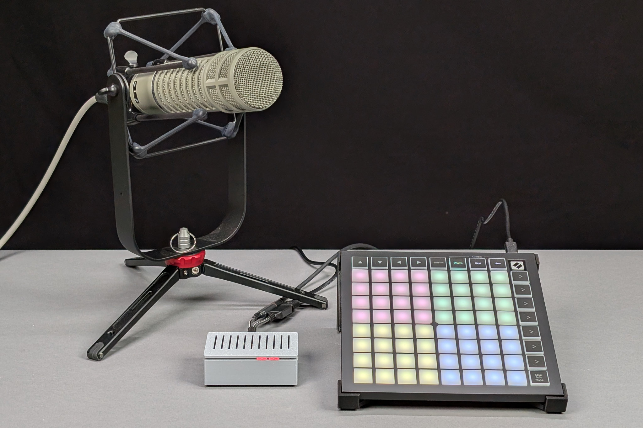
The little gray box plays back sound effects triggered by the Launchpad Mini. It has a line-level output for input to mixer to use during live streams. There’s also a version with a built-in speaker for live in-person sound effects too!
In this project, I use an off-the-shelf MIDI controller to trigger an RP2040 to play out sound effects from a microSD card through an audio DAC and optional amplifier and speaker. Read through to see how to combine the RP2040’s USB host, FatFS, and I2S audio capabilities into a fun audio project and for all the build details!
Motivation
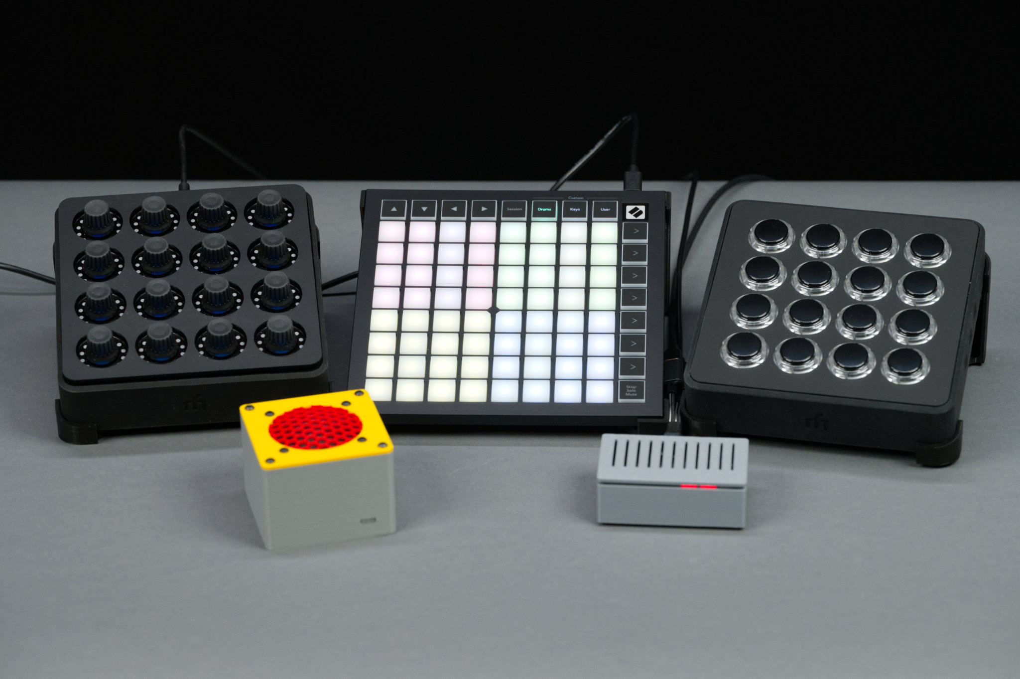
Three USB MIDI controllers and the two versions of this project. The yellow and red has a built-in speaker for use in person. The gray one with the RED LEDs has a line output for a mixer to use during live streams.
This project is a follow on to my Lizard single-purpose soundboard project but supporting many more buttons and audio samples. That project already had the hardware to support tons of audio samples but the number of buttons was limited by the number of available microcontroller pins. After some research, I decided the most practical way to add lots of robust buttons to the project was to use an off-the-shelf MIDI controller like the Midi Fighter Spectra or Novation Launchpad Mini MK3.
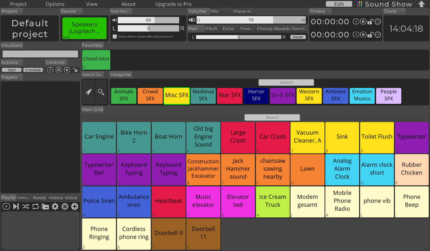
Sound Show screen from their online documentation.
These MIDI controllers normally connect to a PC or Mac using USB and trigger instrument sounds or sound effects in software like Ableton Live or Sound Show. I didn’t want to use a PC to play back sounds because I wanted something small and reliable that booted quickly and had a minimal risk of systems sounds making it into the live audio.
Fortunately, for someone who would like to use these controllers with their own hardware and software, the USB MIDI protocol is standardized, both these devices have robust documentation, and TinyUSB, the RP2040’s USB stack, already has USB MIDI host features.
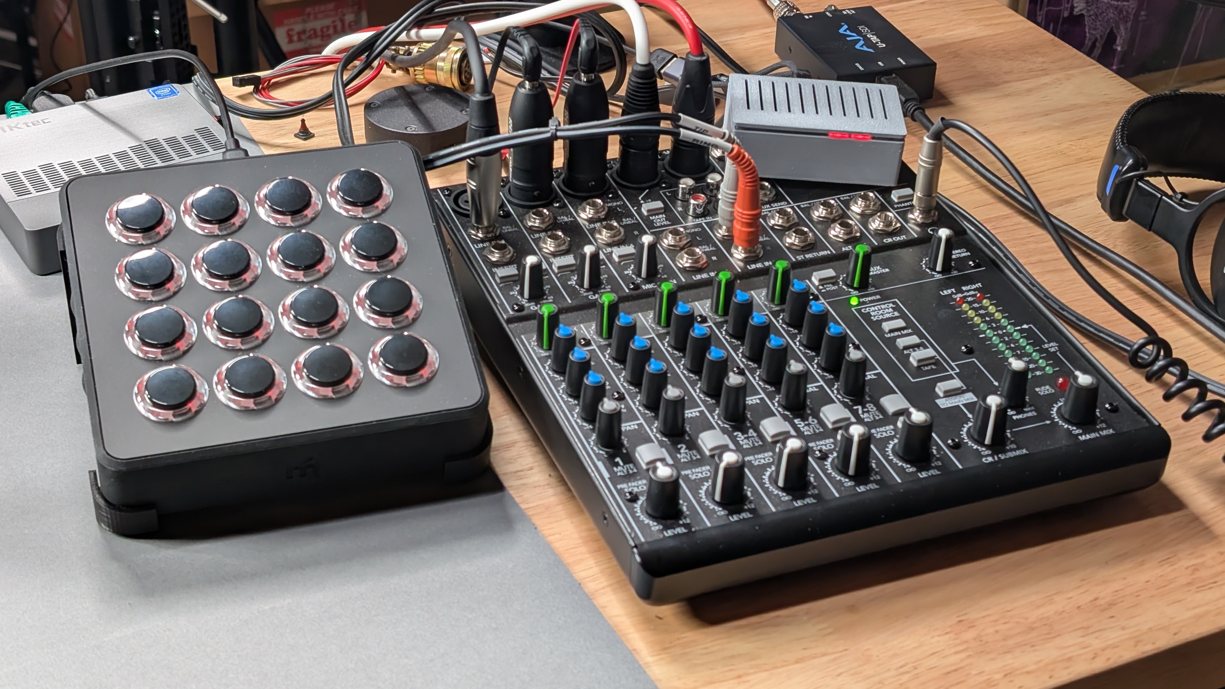
The line out version is small enough to tuck out of the way somewhere. It’s sitting on the top right corner of my mixer.
In addition to more audio samples and buttons, I wanted a version that could feed a line-level signal into an audio mixer for use on calls and when live streaming so this project comes in two versions: the first version contains an amplifier and speaker for use in person and the second has a line-level output for connecting to a mixer. The final change was to develop the software using the Rapsberry PI RP2350/RP2040 C SDK rather than in CircuitPython.
Hardware Prototype
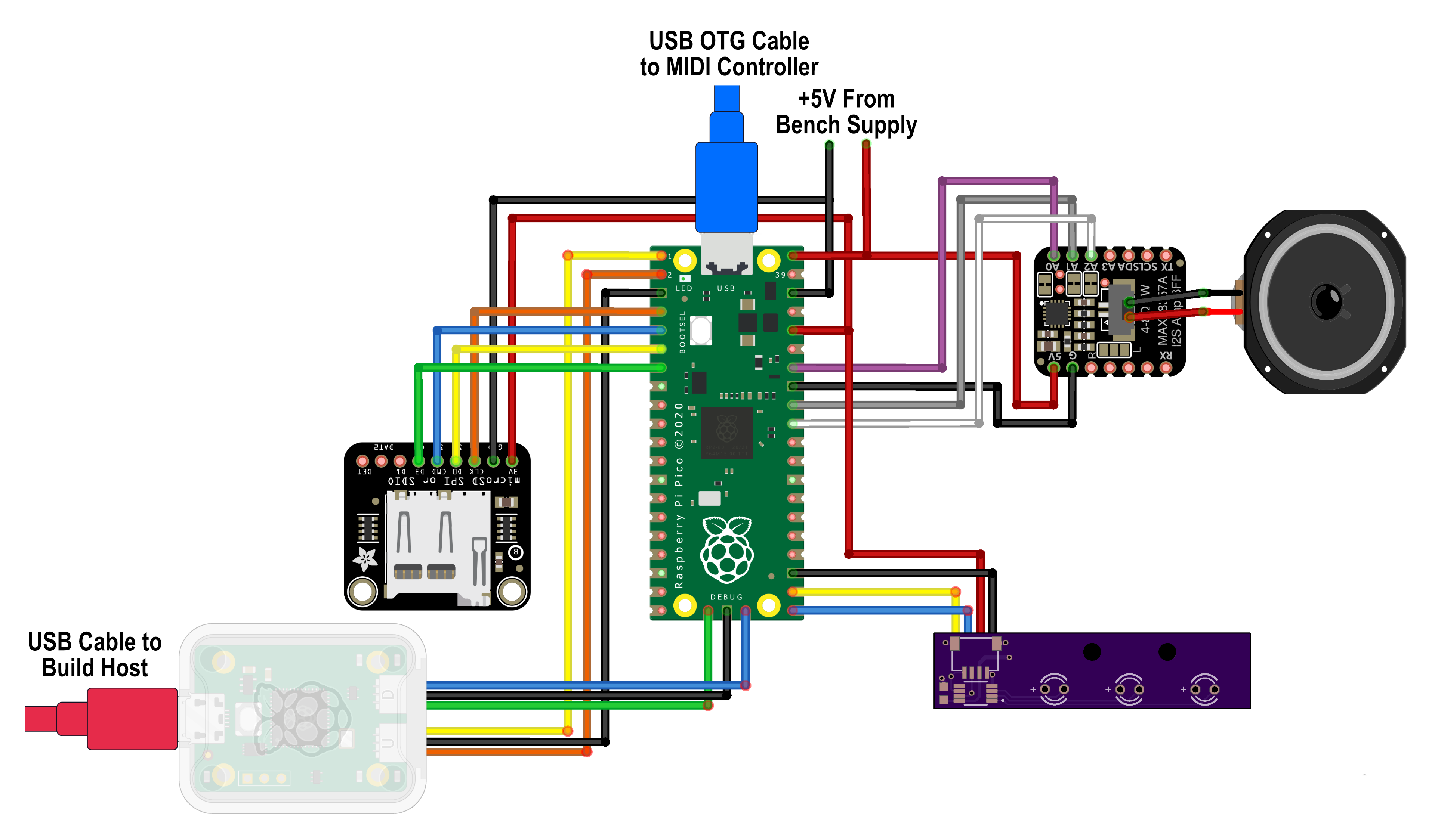
Fritzing diagram of all the development hardware.
Before ordering boards, I prototyped the hardware and software using a Raspberry Pi RP2040 Pico development board. The fritzing sketch for the prototype development is shown in the figure above. The components in the sketch are the following:
- Raspberry Pi RP2040 Pico
- Raspberry Pi Debug Probe
- Adafruit micro SD SPI / SDIO card breakout board
- Adafruit I2S amplifier BFF add-on for QT Py and Xiao
- Generic 40mm diameter, 4 Ohm 5 Watt speaker
- Generic MicroUSB to USB A USB OTG cabkle.
- Custom qwiic three LED board (more on this later).
For a development system, I used a Raspberry Pi 5. For a MIDI controller, I used a Midi Fighter Spectra. I later acquired a Novation Launchpad Mini Mk3 which works too. To make connections to the Pico easier, I used a Pico breakout board (affiliate link) that breaks out the Pico connections to screw terminals and a row of headers. It also helps to anchor everything in place on the workbench.
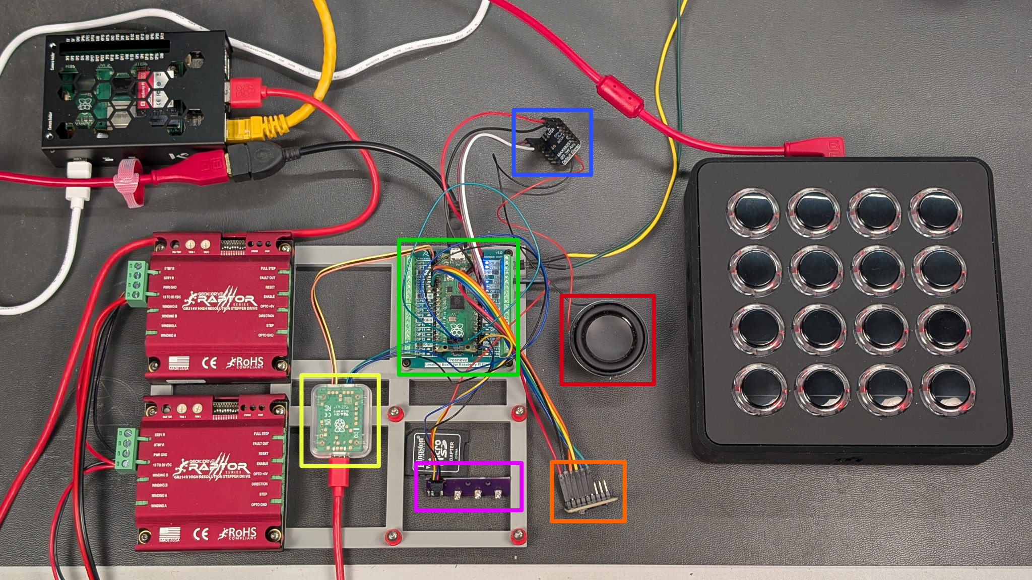
The prototype hardware I used to develop the software and finalize the hardware design.
The photo above shows all the hardware connected together on the workbench. The stepper motor drivers are left over from another Pico project and are not used in this project.
In the upper left, is the Raspberry Pi 5 with the RP2040 C SDK installed on it. It’s connected to my network and the Pico debug probe, highlighted in yellow. The Pico debug probe is in turn connected to the Pico’s SWD connector and UART0. This setup lets me remote into the Pi, debug the Pico, and view the Pico’s serial output from my main desktop rather than trying to use a keyboard and mouse on the workbench.
On the right is the Midi Fighter Spectra connected via the red cable to the USB OTG cable which is connected to the Pico’s micro USB port. To supply power to the project, the yellow and green wires at the top-right corner of the Pico, highlighted in green, are connected to a bench supply set for 5 volts and 500 mA. The rest of the hardware is
- the I2S amp board, highlighted in blue
- the speaker, highlighted in red
- the microSD break out board, highlighted in orange
- the custom qwiic LED board, highlighted in purple
I did not put all the hardware together immediately. I started with just enough hardware to supply power to the Pico, program and debug the Pico, and connect to the MIDI controller. Once the MIDI controller software was working, I added the microSD card hardware. Once that was working, I added the audio hardware. Finally, I added the LEDs.
Software Development Environment
For a software development environment, I used the Raspberry Pi RP2350/RP2400 C/C++ SDK. The SDK is installed using the official instructions on the Raspberry Pi website. The SDK includes the TinyUSB library and the I2S audio libraries but not a useful microSD card or FatFS library.
Unfortunately though, the TinyUSB version currently included with the C/C++ SDK is 0.18 and major revisions were made to the MIDI host stack in 0.19 so the TinyUSB library needs to be updated before it can be used. I deleted the original tinyusb directory in the pico-sdk/lib directory then ran git clone https://github.com/hathach/tinyusb to get the latest version in its place.
If you want to use a specific release, use at least version 0.20.0 which can be downloaded with https://github.com/hathach/tinyusb –branch 0.20.0. There’s probably a way to do this with git without needing to remove the original tinyusb directory but it was pretty late at night and I was in a hurry so I went with the expedient over the judicious.
To access the microSD card, I used the 3rd party no-OS-FatFS-SD-SDIO-SPI-RPi-Pico library. To install the microSD library, clone its GitHub repo into the $PICO_SDK_PATH/lib directory. Once cloned into the lib directory, projects can use it by adding the following line to their CMakeLists.txt:
add_subdirectory(${PICO_SDK_PATH}/lib/no-OS-FatFS-SD-SDIO-SPI-RPi-Pico/src build-fat)
where the first argument is the path to the cloned library’s src directory and the second argument, build-fat, is the name of a directory to build the library in. Cmake will automatically create this directory inside its main build directory. Build-fat could be named anything so long as it doesn’t conflict with any other libraries added to the build.
MIDI Software Test
With the hardware gathered together and the SDK installed, it was time to try to listen to commands from some MIDI controllers. I decided to use the USB MIDI host example as a starting point. Beware that while the examples in this library are still valid, the rest of the code in that repo has been incorporated into the mainline TinyUSB release and is no longer maintained.
Clone, Build, and Download the Example
The following commands should clone the USB MIDI host repository, build the example program, and download it to the Raspberry Pi Pico:
cd
git clone https://github.com/rppicomidi/usb_midi_host.git temp
cd temp/examples/C-code/usb_midi_host_example/
mkdir build
cd build
cmake ..
openocd -f interface/cmsis-dap.cfg -f target/rp2040.cfg -c "adapter speed 5000" -c "program usb_midi_host_example.elf verify reset exit"
Once that’s completed, open a serial terminal to view the outputs of the Pico’s serial port through the Pico debug probe and connect a MIDI controller to the Pico’s USB port using a micro USB OTG cable.
Midi Fighter Spectra Results
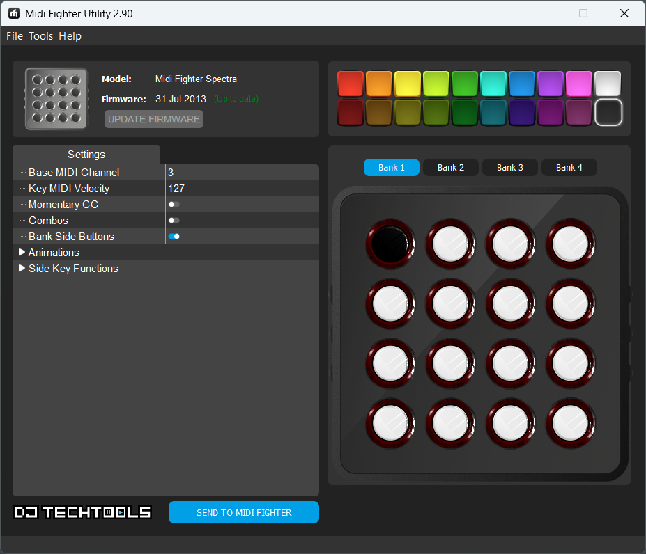
The Midi Fighter Spectra’s configuration is mostly limited to choosing LED ring colors and configuring the device’s side buttons.
I configured my Midi Fighter Spectra as shown above. The settings are mostly limited to choosing the buttons’ LED ring colors and configuring the function of the device’s side buttons. More more information, see the Fighter’s setup page or user guide (PDF).
With the Midi Fighter Spectra connected, these are the results of pushing the top row of buttons in order from left to right:
Pico MIDI Host Example
MIDI Device Index = 0, MIDI device address = 1, 1 IN cables, 1 OUT cables
MIDI Device Index = 0 is unmounted
MIDI Device Index = 0, MIDI device address = 1, 1 IN cables, 1 OUT cables
MIDI RX Cable #0:92 30 7f
MIDI RX Cable #0:82 30 7f
MIDI RX Cable #0:92 31 7f
MIDI RX Cable #0:82 31 7f
MIDI RX Cable #0:92 32 7f
MIDI RX Cable #0:82 32 7f
MIDI RX Cable #0:92 33 7f
MIDI RX Cable #0:82 33 7f
The 0x92 and 0x82 are note on and note off commands on MIDI channel 3. Pressing a button generates a note on command and releasing a button generates a note off command. The 0x2 in the values of 0x92 and 0x82 is MIDI channel 3 which was set for the device in the Midi Fighter configuration utility. The second numbers, 0x30 … 0x33, are the notes corresponding to each button pressed. Finally, the last value, 0x7f, is the note velocity. For more information on what these commands and numbers mean, see SparkFun’s excellent MIDI tutorial.
When it comes time to putting all the software pieces together, I’m going to be interested in the note on commands on channel 3, 0x92, and the notes corresponding to the buttons on the keypad. If you keep pressing buttons, you’ll see the note numbers are not in top-to-bottom, left-to-right order. The note numbers are documented in the user guide (PDF) and we’ll sort them all out later.
Novation Launchpad Mini Mk3 Results
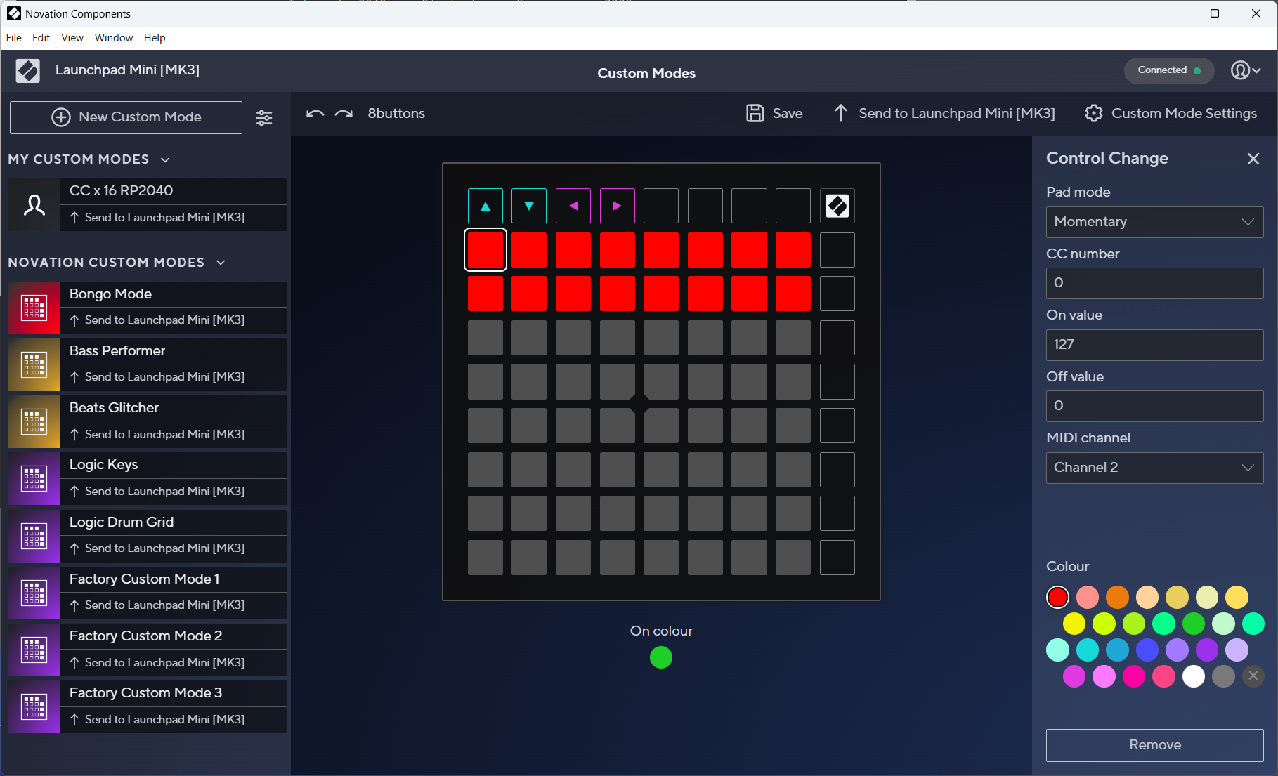
The Novation Launchpad Mini Mk3 configuration software. It has a lot more to configure then the MIdi Fighter Spectra.
The right hand column in the screenshot above shows the configuration of the top left button on my Launchpad. As you can see, the Launchpad is considerably more configurable than the Spectra. I configured all the buttons on the user custom page of the Launchpad to generate MIDI control change (CC) messages on button presses and releases. I also numbered the buttons from 0 to 63 from the top left to the bottom right. For more information on programming the Launchpad, see the Launchpad Mini Mk3 user guide.
Here’s the result of pressing the top left four buttons in order from left to right on the Launchpad:
Pico MIDI Host Example
MIDI Device Index = 0, MIDI device address = 1, 2 IN cables, 2 OUT cables
MIDI RX Cable #1:b1 00 7f
MIDI RX Cable #1:b1 00 00
MIDI RX Cable #1:b1 01 7f
MIDI RX Cable #1:b1 01 00
MIDI RX Cable #1:b1 02 7f
MIDI RX Cable #1:b1 02 00
MIDI RX Cable #1:b1 03 7f
MIDI RX Cable #1:b1 03 00
The 0xb1 is a control change (CC) message on MIDI channel 2. The second numbers, from 0x00 through 0x03, correspond to the button numbers configured previously. Finally, 0x7f is for a button press and 0x00 is for a button release. For more information on what these commands and numbers mean, see SparkFun’s excellent MIDI tutorial.
When it comes time to putting all the software pieces together, I’m going to be interested in the CC commands on channel 2, the button numbers, and when buttons are pressed as indicated by 0x7f.
At this point, we no longer need the temp directory and its contents. It is useful, however, if you get a new MIDI controller or change the configuration of a MIDI controller and want to see what MIDI commands are emitted when a knob is twisted, a slider is moved, or a button is pressed.
microSD Card Software Test
After verifying I could get the USB MIDI host stack to run, I verified I could perform reads and writes to the microSD card using the no-OS-FatFS-SD-SDIO-SPI-RPi-Pico library. I decided to run the simple example included in the repo. This example did take two small modifications to run successfully.
Warning: this example completely erases the inserted microSD card and creates a new file with a hello world in it. You will need a microSD card you don’t mind erasing to run this example.
Create a copy of the simple example in a temp directory:
cd
cp -r pico/pico-sdk/lib/no-OS-FatFS-SD-SDIO-SPI-RPi-Pico/examples/simple ./temp
cd temp
Next, edit CMakeLists.txt to pull the SD card library sources from where they were installed. For me, this was in the lib directory of the Pico SDK installation:
add_subdirectory(${PICO_SDK_PATH}/lib/no-OS-FatFS-SD-SDIO-SPI-RPi-Pico/src build-fat)
Lastly, edit hw_config.c to change the chip select to GPIO5 to match how the hardware prototype is wired:
.ss_gpio = 5 // The SPI slave select GPIO for this SD card
Now, build the project:
mkdir build
cd build
cmake ..
make
Warning: This example will completely erase the microSD card!!! Once the demo runs, the only file on the microSD card will be a file called “filename.txt” containing the string “Hello, world!”
Once it is built, insert a microSD card in the microSD card breakout board and download and ran the generated .elf file:
openocd -f interface/cmsis-dap.cfg -f target/rp2040.cfg -c "adapter speed 5000" -c "program simple_example.elf verify reset exit"
After running the project, power down the target and use a PC or Mac to verify the card was formatted and the file was created and contained the correct contents.
I2S Audio Software Test
So far, so good! Both the MIDI and the microSD card were working, but could I create audio? The pico-playground includes a program to generate a sine wave on a connected I2S DAC using the pico-extras i2s library, both of which are installed as part of the Pico C/C++ SDK. This sounded like a good starting point for making some noise. It was also the most difficult example to get to compile because I had to make my own CMakeLists.txt.
cd
mkdir temp
cd temp
cp $PICO_SDK_PATH/../pico-playground/audio/sine_wave/sine_wave.c .
cp $PICO_SDK_PATH/external/pico_sdk_import.cmake .
cp $PICO_SDK_PATH/../pico-extras/external/pico_extras_import.cmake .
In the temp directory, create a new CMakeLists.txt with the following contents:
cmake_minimum_required(VERSION 3.13)

set(BOARD pico_sdk)
include(pico_sdk_import.cmake)
include(pico_extras_import.cmake)

project(pico_audio_i2s C CXX ASM)
set(CMAKE_C_STANDARD 11)
set(CMAKE_CXX_STANDARD 17)
pico_sdk_init()

add_executable(sine_wave_i2s
        sine_wave.c
        )

target_link_libraries(sine_wave_i2s PRIVATE
        pico_stdlib
        pico_audio_i2s
        )

target_compile_definitions(sine_wave_i2s PRIVATE
        # compile time configuration of I2S
        PICO_AUDIO_I2S_MONO_INPUT=1
        #define for our example code
        USE_AUDIO_I2S=1
        )

pico_enable_stdio_usb(sine_wave_i2s 0)
pico_enable_stdio_uart(sine_wave_i2s 1)

# create map/bin/hex file etc.
pico_add_extra_outputs(sine_wave_i2s)
Now create the build directory, build the project, and download the binary to the Pico:
mkdir build
cd build
cmake ..
make
openocd -f interface/cmsis-dap.cfg -f target/rp2040.cfg -c "adapter speed 5000" -c "program sine_wave_i2s.elf verify reset exit"
If you have a terminal connected to the Pico, you can use different keys, as documented in sine_wave.c, to change the volume and pitch of the tone. I used this example to test the Pico I2S capabilities with both the MAX98357-based I2S Amplifier BFF board and a PCM5100 DAC breakout board. This ensured that my hardware and software could provide either a speaker level or line out level depending on the connected DAC.
Pulling All the Software Blocks Together
The next step was to put all these building blocks together into a program to detect button presses on the MIDI controller and then, in response to these button presses, read audio samples from the microSD card and play them out through the attached I2S DAC.
The first step in main.c is to initialize all the hardware, initialize a queue for moving button presses from the USB MIDI receive callback to the main loop, and initialize a periodic timer that’s used to blink the LED on the Pico dev board.
Once everything is initialized, the main loop is entered. This loop performs the following functions:
- Calls the TinyUSB main loop function, tuh_task.
- Attempts to mount the microSD card if one is not already mounted.
- Attempts to copy audio samples from a file to a free audio buffer if a file is open and a free audio buffer is available. If an audio buffer is available and a file is not opened, zero samples are copied to the available audio buffer.
- If a new button is pressed, closes any playing audio file and opens the next audio file to play. The samples will be copied from the newly opened audio file to an audio buffer the next time a free audio buffer is available.
- If support for the I2C-based status LEDs is compiled into the project, updates the LEDs to reflect the current state of the hardware.
The audio buffers are sized so that one audio buffer is equal to one block of audio samples on the microSD card: 128 stereo 16 bit samples are 512 bytes which is the size of block on the filesystem.
Build Instructions
To build the audio player, first clone the repo, cd into the source directory, then make and enter the build directory:
git clone https://github.com/bikerglen/rp2040-midi-player.git
cd rp2040-midi-player/src
mkdir build
cd build
Next, run a variation of cmake based on the hardware type. For the Pico-based protoype hardware:
cmake ..
For the Adafruit QT PY RP2040-based hardware used by the boards described later in this blog post:
cmake .. -DPICO_BOARD=adafruit_qtpy_rp2040
If you decide to add the I2C-based LED indicators to the project, LED support can be compiled into the project by modifying the cmake command line to include either -DSTATUS_LED_CONFIG=single or -DSTATUS_LED_CONFIG=triple. The function of these is described later.
For example, to build using the real hardware with a single status LED, the cmake line would be:
cmake .. -DPICO_BOARD=adafruit_qtpy_rp2040 -DSTATUS_LED_CONFIG=single
After running cmake to generate the required makefiles, run make:
make
This will generate both a .elf file for use with the Pico debug probe and a .uf2 file to use with the RP2040’s UF2 bootloader. If you decide to change the build configuration and need to rerun cmake, you can either delete the CMakeCache.txt file or remove the entire build directory.
Formatting and Naming Audio Files for the Player
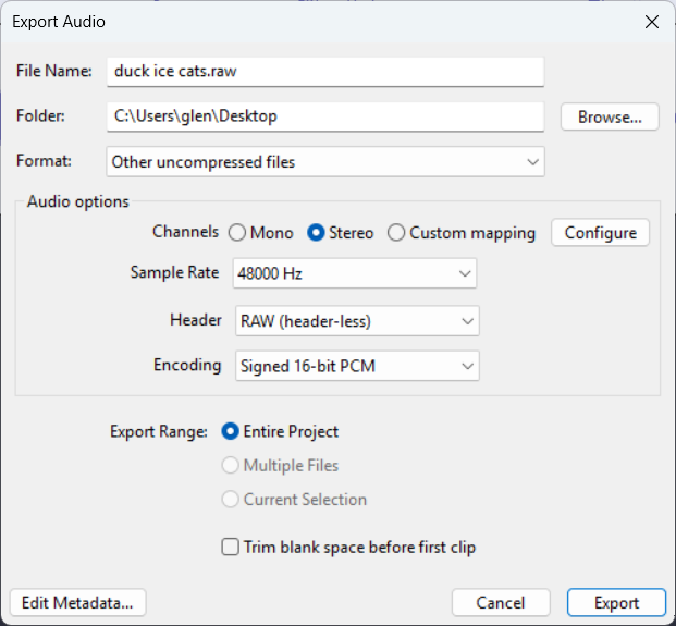
Export settings to format audio samples for the audio player.
The audio player uses headerless (raw) stereo audio files sampled at 48 kHz. A stereo pair of stereo samples is ordered left then right. Each sample is 16 bits and in little endian byte order. Files in this format can be exported from Audacity using the settings shown in the Export Audio dialog box shown above. Alternatively, files can be converted using FFMPEG:
ffmpeg -i in_file.mp3 -f s16le -acodec pcm_s16le -ar 48000 out_file.raw
Files should be named in the format effectXX.raw where XX is a two digit hex number corresponding to the button that triggers the audio sample, e.g. effect00.raw, effect01.raw, …, effectff.raw. I will accept pull requests from anyone who wants to add WAVE input or a mapping file to map buttons to audio files.
Fixing Stuttering Audio
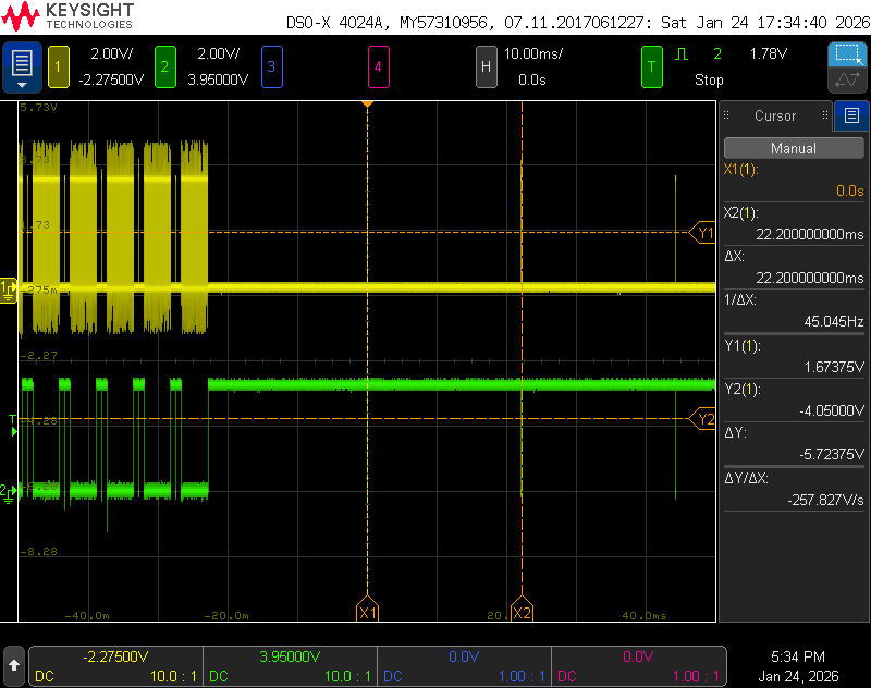
Scope traces showing the microSD card block read command occasionally taking an excessive amount of time to complete.
After getting the software to mostly work, I had a problem with stuttering audio. I suspected some task inside my main loop wasn’t completing in time to service and fill the next audio buffer. To narrow the problem down, I decided to profile key portions of the code using an oscilloscope and a few of the unused GPIO’s on the Pico. By surrounding each key task in the main loop with a gpio_put call to turn on a GPIO before calling the task and another gpio_put call to turn off a GPIO after calling the task, I could see how long each task was taking to complete.
The yellow trace in the oscilloscope screen capture above shows the amount of time spent in the tuh_task call. The green trace shows the amount of time spent reading audio samples from the microSD card then filling the audio buffers with those samples. By looking at the two traces, I quickly narrowed the problem down to the latter of the two tasks. The tuh_task USB tasks always completed quickly. Refilling the audio buffers normally completed in a few milliseconds, but occasionally it’d take over 20 milliseconds to fill one buffer!
I kept moving the gpio_put calls for the green trace deeper and deeper into the FatFS and SD card driver stack until they were around the call to send the read block command to the microSD card and await the microSD card response. The microSD card I was using would periodically take 22 ms to complete the read block command—and it’d do this for six read block commands in a row! The solution turned out to be an easy fix: I changed to a different brand of microSD cards and the problem disappeared.
Remounting the microSD Card after an Error or Removal
The second issue I had was that once the microSD card code hit an error, it’d never recover. The solution to this was a bit more difficult to find. After tons of searching, I found a forum post where someone else was having a similar issue. The solution turned out to be adding these lines of code to unmount the microSD card and tell the underlying hardware driver that the card has been removed:
      f_unmount ("");
      sd_card_t *sd_card_p = sd_get_by_num(0);
      sd_card_p->state.m_Status |= STA_NOINIT | STA_NODISK;
These would normally be called in response to the card detect pin detecting the card being removed. I don’t have a card detect pin so the best I can do is call these after an error and then try to remount the card until successful.
Boards
With both the hardware and software working, it was time to create some circuit boards and make the project a bit more permanent and reliable. Since this project comes in two versions, there’s two different circuit board designs. The first design is for the amplifier and speaker version of the project. The second design is for the DAC-only, line out version of the project.
Where’s the Power Connector?!
While working on the board designs, I discovered that there are USB C on-the-go cables for adding a keyboard or mouse to a phone and, importantly, powering both the phone and keyboard or mouse from a USB wall adapter simultaneously. These are typically sold as USB C OTG adapters with power.
I ordered a few and verified they could power my target system, power the MIDI controller, and pass data from the MIDI controller to the target system. This eliminated the need to add a separate DC jack or USB C connector to power the project. This allowed the board designs to be simpler and the finished projects to be quite a bit smaller. There’s a section at the end of this blog post on how to use these cables to connect everything together.
Speaker Version
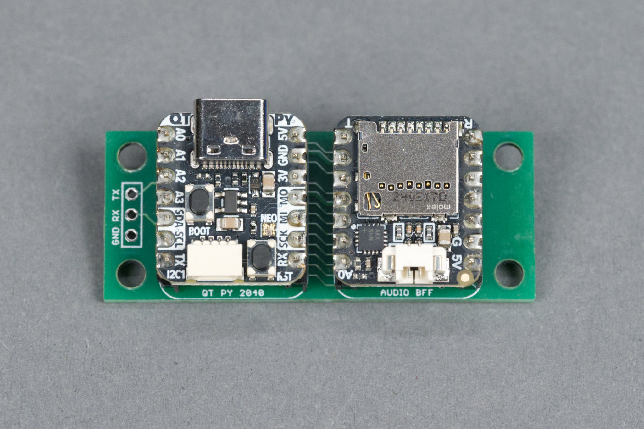
The speaker version circuit board with the Adafruit QT PY RP2040 and Audio BFF boards plugged into it.
The completed speaker version board is shown above. The boards for this project are incredibly simple as they serve only to connect pins on the daughter development boards together and mechanically hold the boards in place.
Schematic
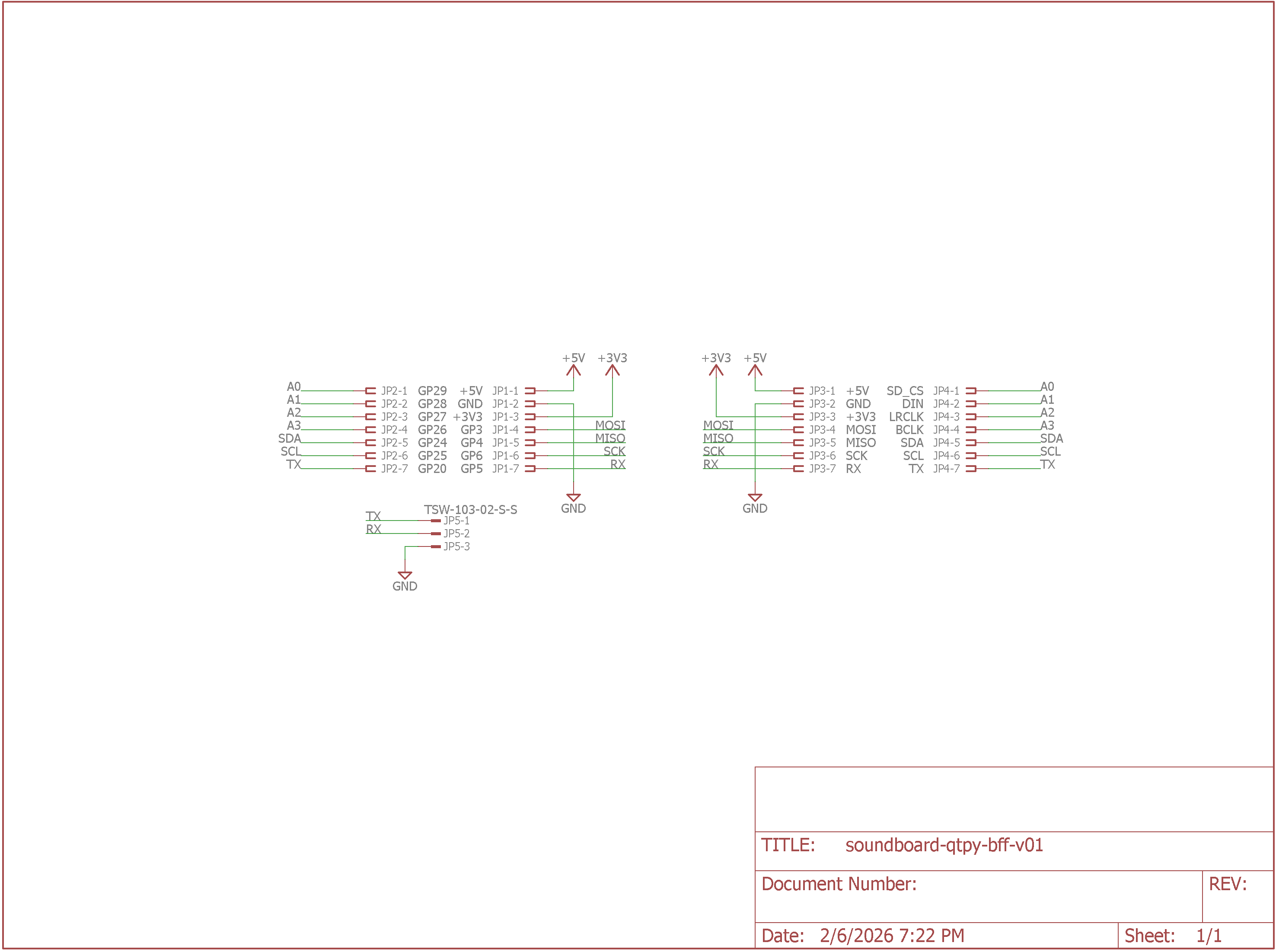
Speaker version schematic.
The schematic is shown above. Like I said, it just connects pins on the dev boards together. There’s also a 3-pin header that’s connected to the QT PY’s UART for debugging if needed.
Board Layout
Speaker version PCB layout.
The board layout is shown above. The QT PY RP2040 board goes on the left and the Audio BFF board goes on the right. The board mounts to the bottom of the enclosure and against its rear wall. This makes the USB C port and microSD card slot accessible from the rear of the enclosure. I used low-profile headers and header sockets so the between board spacing is theoretically 7.62 mm. It works out in practice to about 7.8 mm.
Bill of Materials
The bill of materials for the speaker version is shown in the table below.
| Quantity | Description | Manufacturer | Part Number |
|---|---|---|---|
| 1 | QT PY RP2040 | Adafruit | 4900 |
| 1 | Audio BFF for QT PY or Xiao | Adafruit | 5769 |
| 1 | 3-pin standard header | — | — |
| 4 | 7-pin low profile headers, cut from larger strip | Adafruit | 3009 |
| 4 | 7-pin low profile header sockets, cut from a 50-pin strip | Samtec | CES-150-01-T-S |
| 4 | 0.315″ Diameter Rubber Feet | 3M | SJ5076 |
| 1 | 2″, 4 ohm, 10 W black speaker | — | — |
| 1 | USB C OTG Adapter with Power | — | — |
| 1 | Molex PicoBlade 2-pin Cable – 200mm | Adafruit | 3922 |
| 4 | M3 x 4 mm | — | — |
| 8 | M3 x 8 mm | — | — |
| 4 | M3 washers | — | — |
| 4 | M3 hex nuts | — | — |
| 2 | M2 x 6 mm | — | — |
Line Out Version
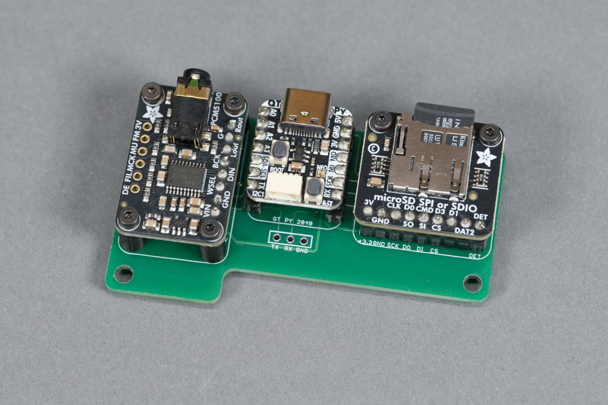
The line out version circuit board with the PCM5100 break out board, Adafruit QT PY RP2040 dev board, and microSD breakout board plugged into it.
The completed line out version of the board is shown above. The boards for this project are incredibly simple as they serve only to connect pins on the daughter development boards together and mechanically hold the boards in place.
Schematic
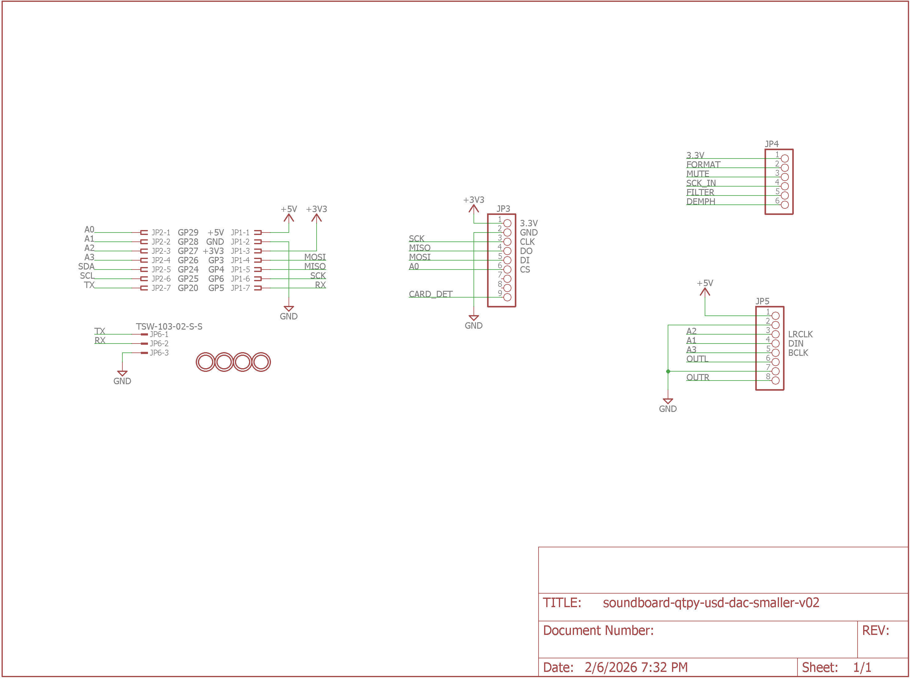
DAC version schematic.
The schematic is shown above. Like I said, it just connects pins on the dev boards together. There’s also a 3-pin header that’s connected to the QT PY’s UART for debugging if needed.
Board Layout
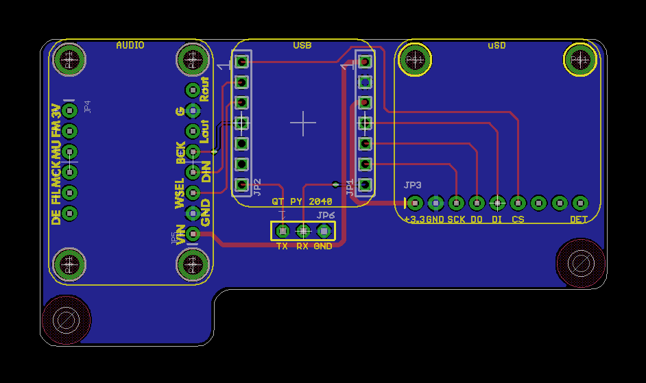
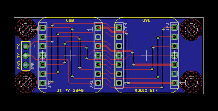
DAC version PCB layout.
The board layout is shown above. The PCM5100 breakout board is on the left, the QT PY RP2040 board is in the middle, and the microSD breakout board is on the right. The board mounts to the bottom of the enclosure and against its rear wall. This makes the 3.5 mm line out jack, the USB C port and the microSD card slot accessible from the rear of the enclosure. I used low-profile headers and header sockets so the between board spacing is theoretically 7.62 mm. It works out in practice to about 7.8 mm. The daughter boards are held in place using six 3D-printed standoffs.
Bill of Materials
The bill of materials for the line out version is shown in the table below.
| Quantity | Description | Manufacturer | Part Number |
|---|---|---|---|
| 1 | PCM5100 breakout board | Adafruit | 6251 |
| 1 | QT PY RP2040 | Adafruit | 4900 |
| 1 | microSD SPI/SDIO breakout board | Adafruit | 4682 |
| 1 | 3-pin standard header | — | — |
| 2 | 7-pin low profile headers, cut from larger strip | Adafruit | 3009 |
| 2 | 7-pin low profile header sockets, cut from a 50-pin strip | Samtec | CES-150-01-T-S |
| 1 | 8-pin low profile headers, cut from larger strip | Adafruit | 3009 |
| 1 | 8-pin low profile header sockets, cut from a 50-pin strip | Samtec | CES-150-01-T-S |
| 1 | 9-pin low profile headers, cut from larger strip | Adafruit | 3009 |
| 1 | 9-pin low profile header sockets, cut from a 50-pin strip | Samtec | CES-150-01-T-S |
| 4 | 0.315″ Diameter Rubber Feet | 3M | SJ5076 |
| 1 | USB C OTG Adapter with Power | — | — |
| 2 | M3 x 4 mm screws | — | — |
| 14 | M2 x 4 mm screws | — | — |
| 6 | 3d printed M2 x 5 mm x 7.8 mm standoffs | — | — |
Adding LEDs using I2C
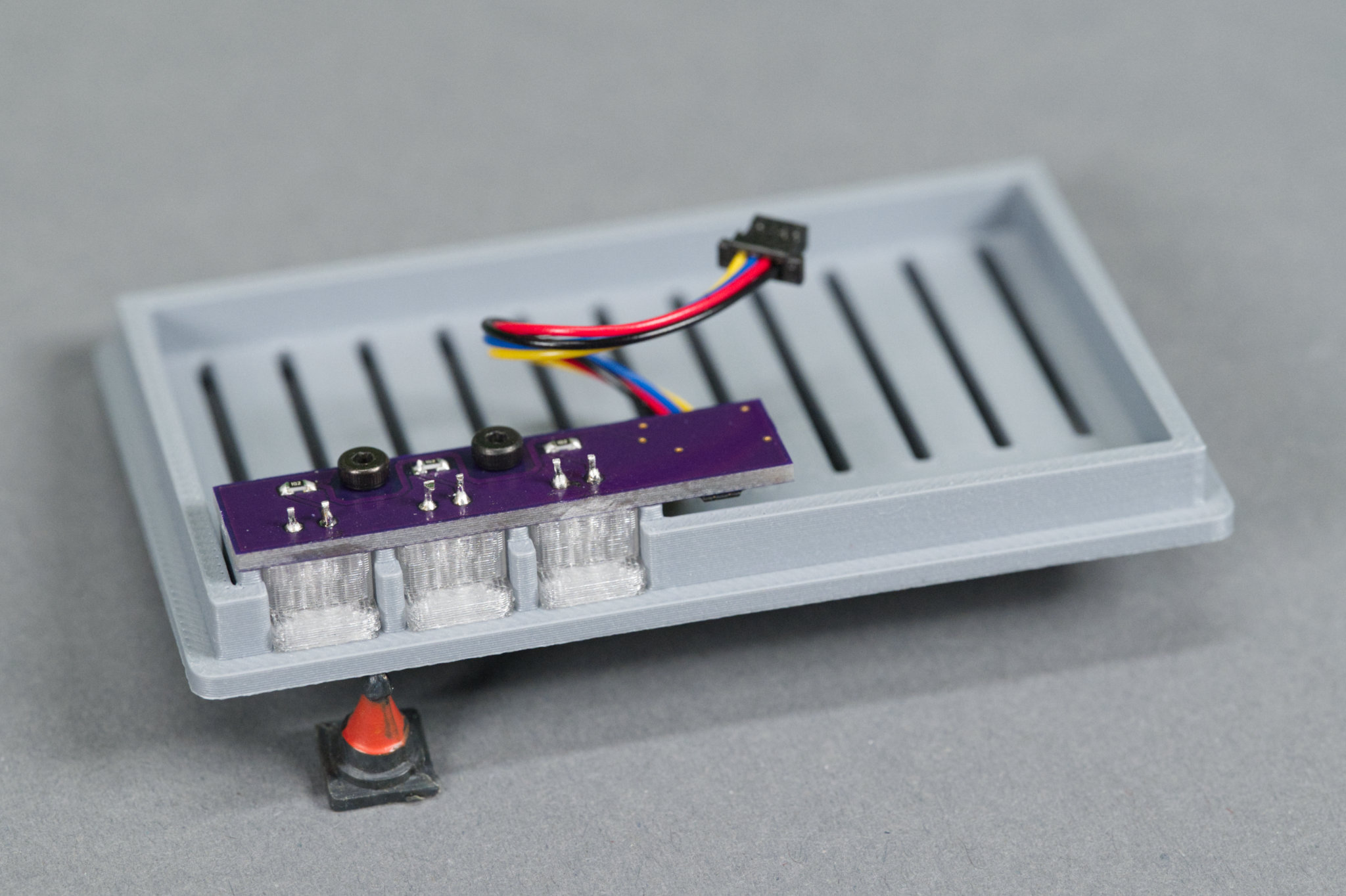
The LED board mounted to the underside of the line out version’s lid.
After prototyping the hardware and software and experimenting with a few different case designs, I decided I wanted some LEDs to indicate that a MIDI controller was connected, the microSD card was mounted, and the unit was ready to play samples. I really like the looks of the PiSCSI Mini Case and the implementation of the LED and light guide on that case so I decided to design a similar light guide and add some LEDs to the project!
Hardware
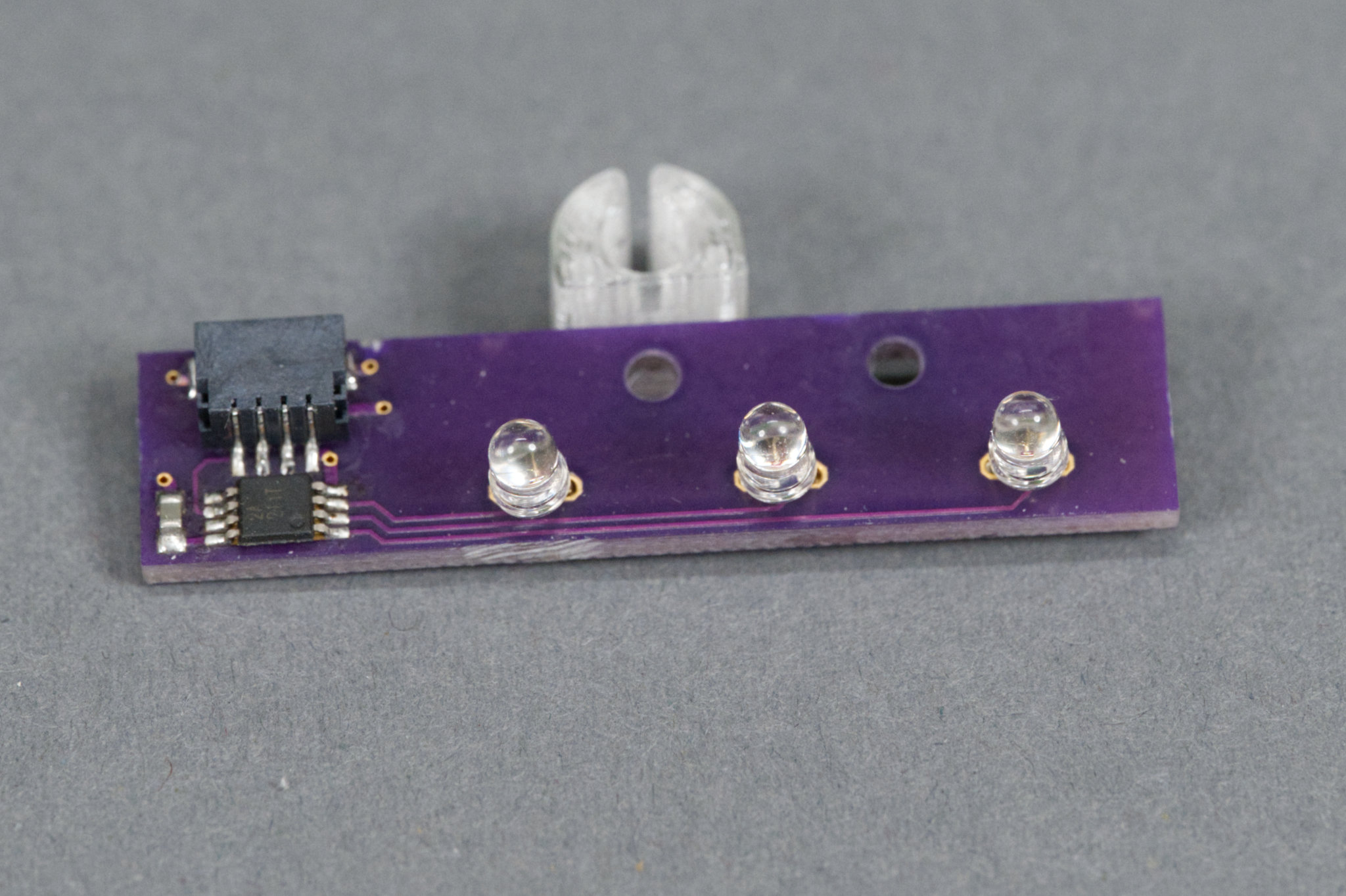
The top side of the LED board showing the JST connector, I2C IO expander, and three LEDs. Behind the board is a light guide.
I liked the design of the PiSCSI LED and light guide but I didn’t like the idea of soldering and heat shrinking a bunch of resistors and wires together, especially since I wanted up to three LEDs. I decided to build a small board that connected to the QT PY RP2040’s qwiic connector via a short cable and could drive up to three LEDs using a TI TCA9536 I2C IO expander.
Schematic
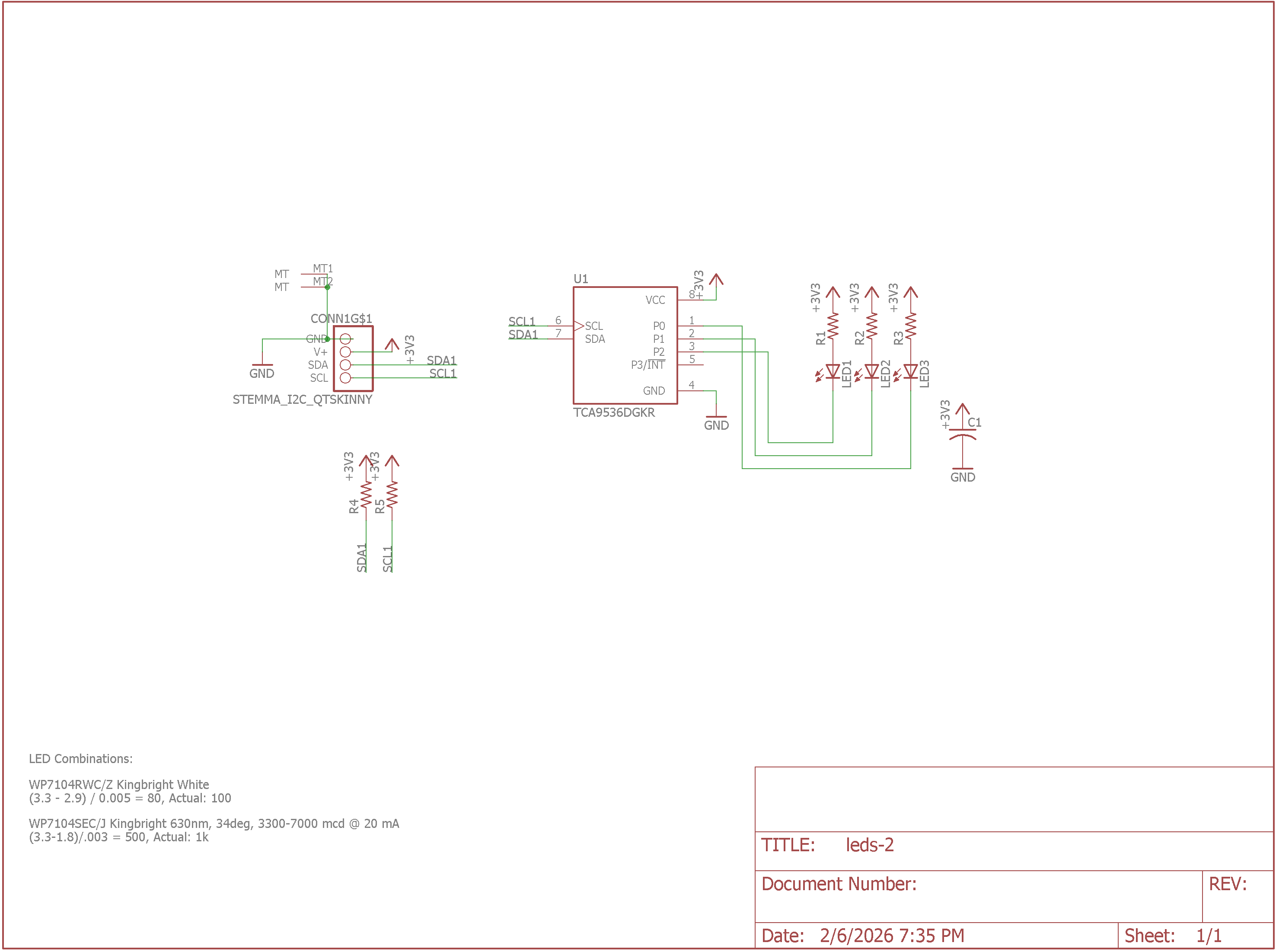
Schematic of the I2C IO expander LED board.
The schematic for the LED board is shown above. There’s a 1 mm pitch JST SH connector for connecting to the I2C qwiic host. That connector connects power, ground, SDA, and SCL to the TCA9536 I2C IO expander. The IO expander then drives up to three LEDs through current limiting resistors. There’s an option to add pullup resistors to the SDA and SCL signals if the I2C host doesn’t already have them.
Board
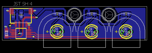
I2C IO expander LED board layout.
After drawing the schematic, the requirements for the board were that the LEDs would be spaced wide enough apart to accommodate the light guides with 2 mm of space between each guide. It would also have 2.2 mm holes for M2 screws to connect it to either the base or the lid of a 3D-printed enclosure. The completed board layout is shown above.
The outlines of the light guides and the spaces between the light guides are shown with gray lines. The space between the light guides is enough room for a 3D printed separator to prevent light from bleeding between the guides. The screw heads overlap a bit into this space but not enough to affect the construction or operation of a separator.
Bill of Materials
The bill of materials for the LED board is shown in the table below. I selected LEDs with a viewing angle between 30° and 40°. Narrower viewing angles don’t throw enough light sideways to light up the light guide very well.
| Quantity | Description | Manufacturer | Part Number |
|---|---|---|---|
| 1 | JST SH 1 mm pitch, 4 position, surface mount socket | Adafruit | 4208 |
| 1 | 4 port I2C IO expander | Texas Instruments | TCA9536DGKR |
| 1 | 0.1 µF 0603 capacitor | generic | — |
| 2 | 4.7 kΩ 0603 resistor | generic | — |
| 3 | 100 Ω – 1 kΩ 0603 resistors depending on LED forward voltage and desired current / brightness | generic | — |
| 3 | T-1 3 mm LEDs | generic | — |
| 1 | 50 mm JST SH 1 mm pitch, 4 position cable assembly | Adafruit | 4399 |
Light Guides
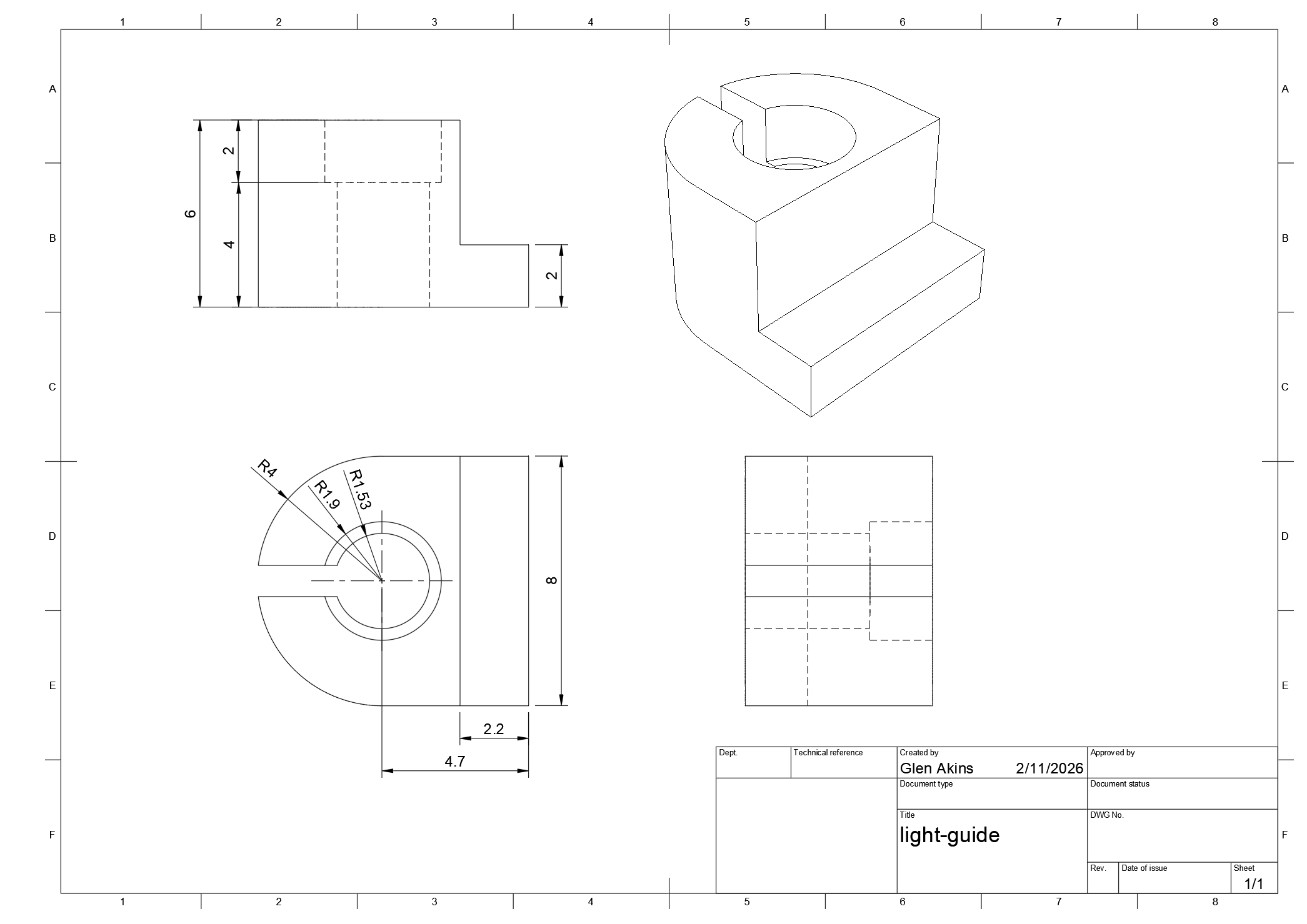
Dimensioned drawing of the light guide.
The diagram above shows a sketch of the light guide including its dimensions. It’s 8 mm wide and 6 mm tall. The visible window is 8 mm x 2 mm. A hole in the center is sized to accommodate most T-1 3 mm LEDs.

Getting ready to print the light guides.
I printed the light guides five at a time out of Bambu Lab clear transparent PETG filament. I used the default 0.20 mm standard settings but placed the seam on the back and upped the number of wall loops to 4. Increasing the wall loops ensured the entire light guide was filled in solid.
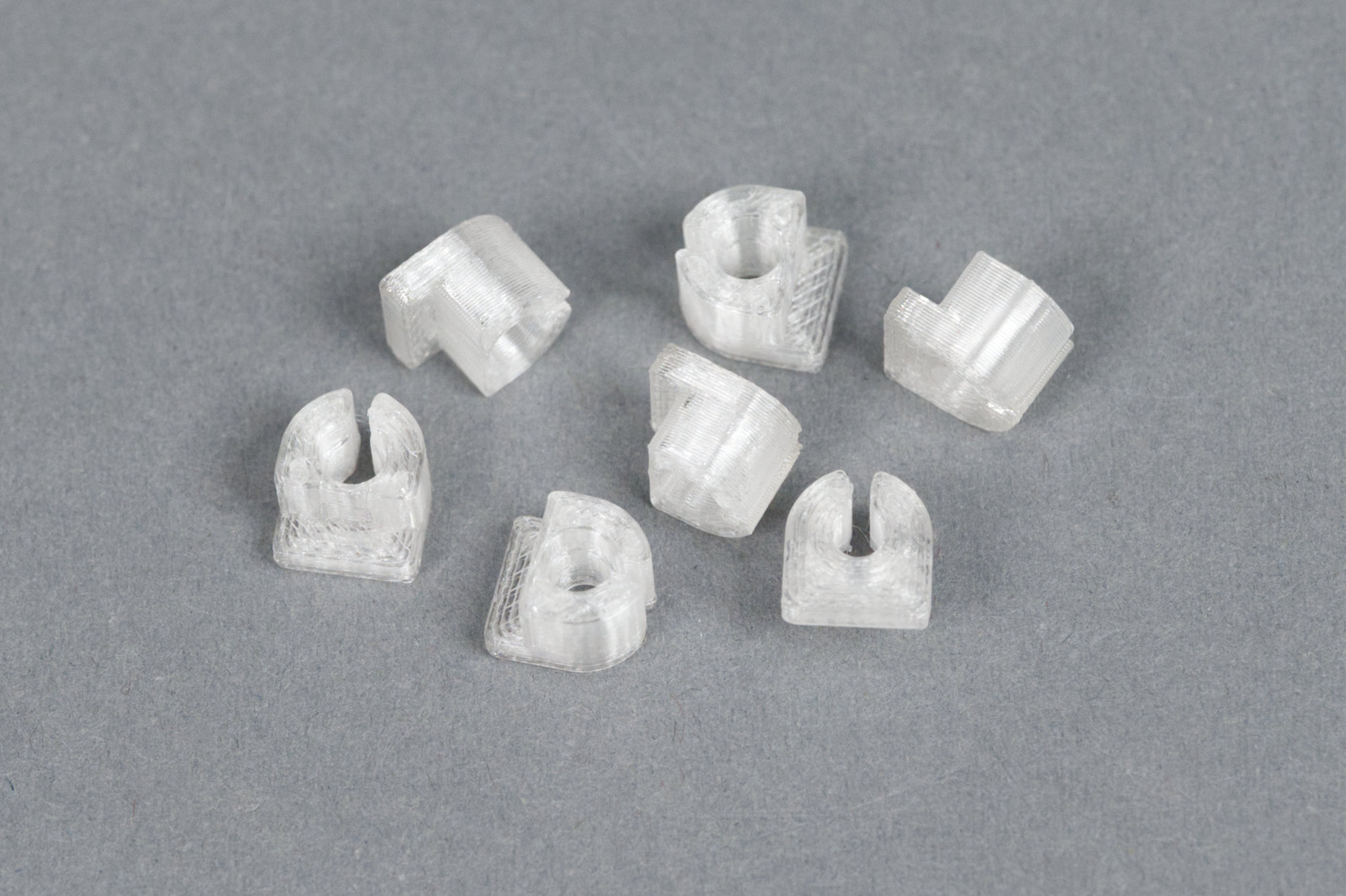
The printed light guides.
The photo above shows a handful of the printed light guides. Since they’re not completely transparent, they will evenly diffuse the light from the LED across the entire visible surface of the light guide when it’s in the enclosure.
Assembly
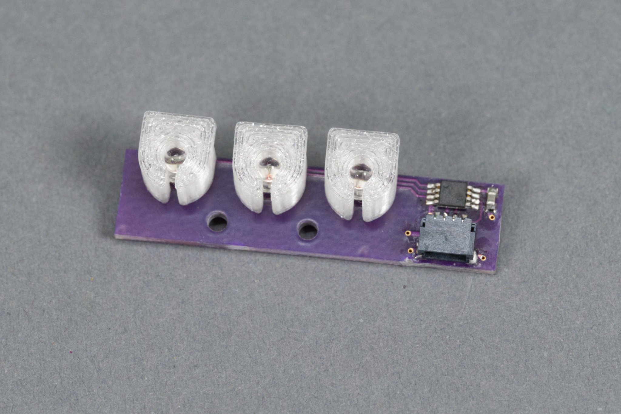
The LEDs mostly hold the light guides in place. The entire assembly mounts into a cavity with cutouts for each light guide then screws hold it in place.
The photo above shows the light guides pressed onto the LEDs on the circuit board. For the DAC / line out version of the project, I populated all three LEDs and light guides and it will mount into the underside of the lid of the enclosure. For the speaker version of this project, I only populated the right-most LED and light guide then printed another small piece to secure the assembly to the bottom of the inside of the enclosure base. Details to follow.
Software
With the boards assembled, it was time to write some software to test the board. This example is available in the examples/i2c_expander_example directory of the player’s GitHub repository. Key sections of the code are highlighted below.
First some defines for the I2C instance and I2C pins on the Pico:
#define I2C_NUMBER  0
#define I2C_SDA_PIN 16
#define I2C_SCL_PIN 17

#define TCA9536_I2C_ADDRESS 0x41
Next configure the Pico’s I2C interface:
  // configure rp2040 i2c hardware
  i2c_init (I2C_INSTANCE(I2C_NUMBER), 100 * 1000);
  gpio_set_function(I2C_SDA_PIN, GPIO_FUNC_I2C);
  gpio_set_function(I2C_SCL_PIN, GPIO_FUNC_I2C);
  gpio_pull_up(I2C_SDA_PIN);
  gpio_pull_up(I2C_SCL_PIN);
This code initializes the I2C I/O expander and turns all the LEDs off:
  // set all four tca9536 pins to outputs by writing config reg 0x03 to 0x00
  data[0] = 0x03;
  data[1] = 0x00;
  i2c_write_blocking (I2C_INSTANCE(I2C_NUMBER), TCA9536_I2C_ADDRESS, data, 2, false);

  // set all four tca9536 outputs high by writing output port reg 0x01 to 0x0F (all leds off)
  data[0] = 0x01;
  data[1] = 0x0F;
  i2c_write_blocking (I2C_INSTANCE(I2C_NUMBER), TCA9536_I2C_ADDRESS, data, 2, false);
Finally, individual LEDs can be controlled by setting or clearing bits in the I/O expander’s output register. Setting a bit turns the LED off and clearing a bit turns the LED on. The left led is controlled by bit 2:
    // left led on
    data[0] = 0x01;
    data[1] = 0x0B;
    i2c_write_blocking (I2C_INSTANCE(I2C_NUMBER), TCA9536_I2C_ADDRESS, data, 2, false);
The middle led is controlled by bit 1:
    // middle led on
    data[0] = 0x01;
    data[1] = 0x0d;
    i2c_write_blocking (I2C_INSTANCE(I2C_NUMBER), TCA9536_I2C_ADDRESS, data, 2, false);
The right led is controlled by bit 0:
    // right led on
    data[0] = 0x01;
    data[1] = 0x0e;
    i2c_write_blocking (I2C_INSTANCE(I2C_NUMBER), TCA9536_I2C_ADDRESS, data, 2, false);
The i2c_expander_example initializes everything then runs a loop that blinks the LEDs one at a time from left to right. The example can be built and run by changing into the i2c_expander_example directory and executing the following commands:
mkdir build
cd build
cmake ..
make
openocd -f interface/cmsis-dap.cfg -f target/rp2040.cfg -c "adapter speed 5000" -c "program i2c_example.elf verify reset exit"
The main audio player uses these building blocks to control the LEDs in response to the state of the system. The number of LEDs used by the main audio player is configured by supplying additional command line options to cmake when building the player. Adding -DSTATUS_LED_CONFIG=single configures the player to use a single LED and -DSTATUS_LED_CONFIG=triple configures the player to use three LEDs.
When three LEDs are configured, the LEDs indicate left to right: the MIDI controller connection state, the microSD card error state, and whether a sample is playing or not. When only one LED is configured, the LED indicates a MIDI controller is connected and the microSD card is mounted without errors. When the LED is on, the system is ready to play samples. The LED does not change state when a sample is playing.
Enclosures
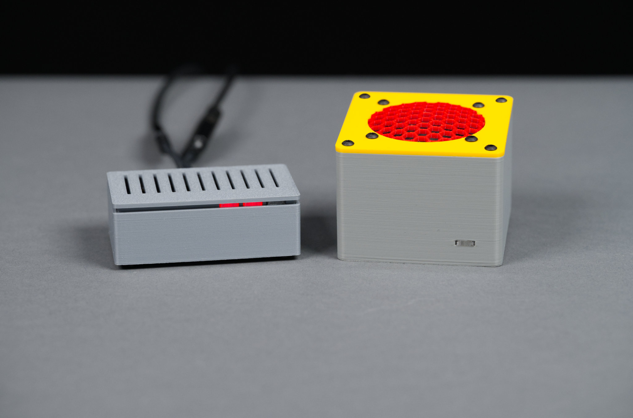
On the left is the completed line out version. On the right is the speaker version.
Since this project comes into two variations, I needed two different enclosures. The first enclosure is for the speaker version of the project that includes a small amplifier and speaker. The second enclosure is for the line out version of the project that includes a DAC with line out on a stereo 3.5 mm jack.
Speaker Version
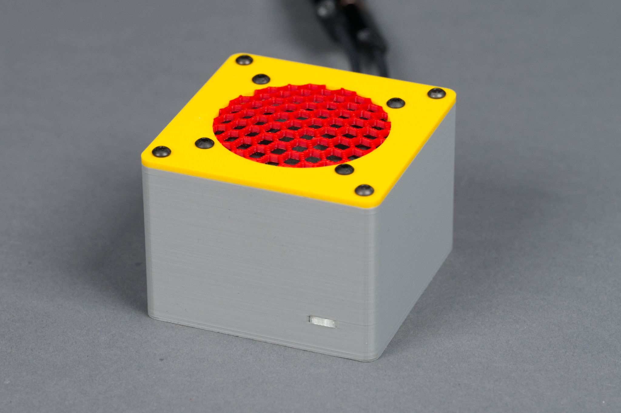
Front view of the speaker version.
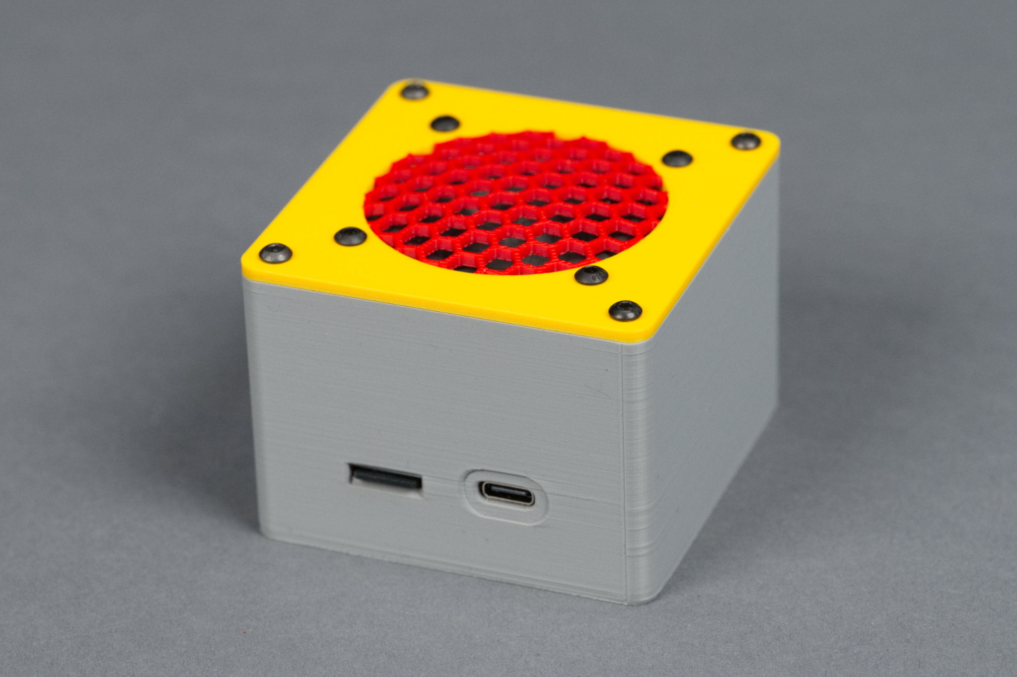
Rear view of the speaker version.
The speaker version of the completed project is shown in the photos above. This enclosure was modeled after the Lizard project’s enclosure. It’s been made square and slightly taller. It includes the same raised hex dome speaker grill printed out of a separate color from the rest of the lid.
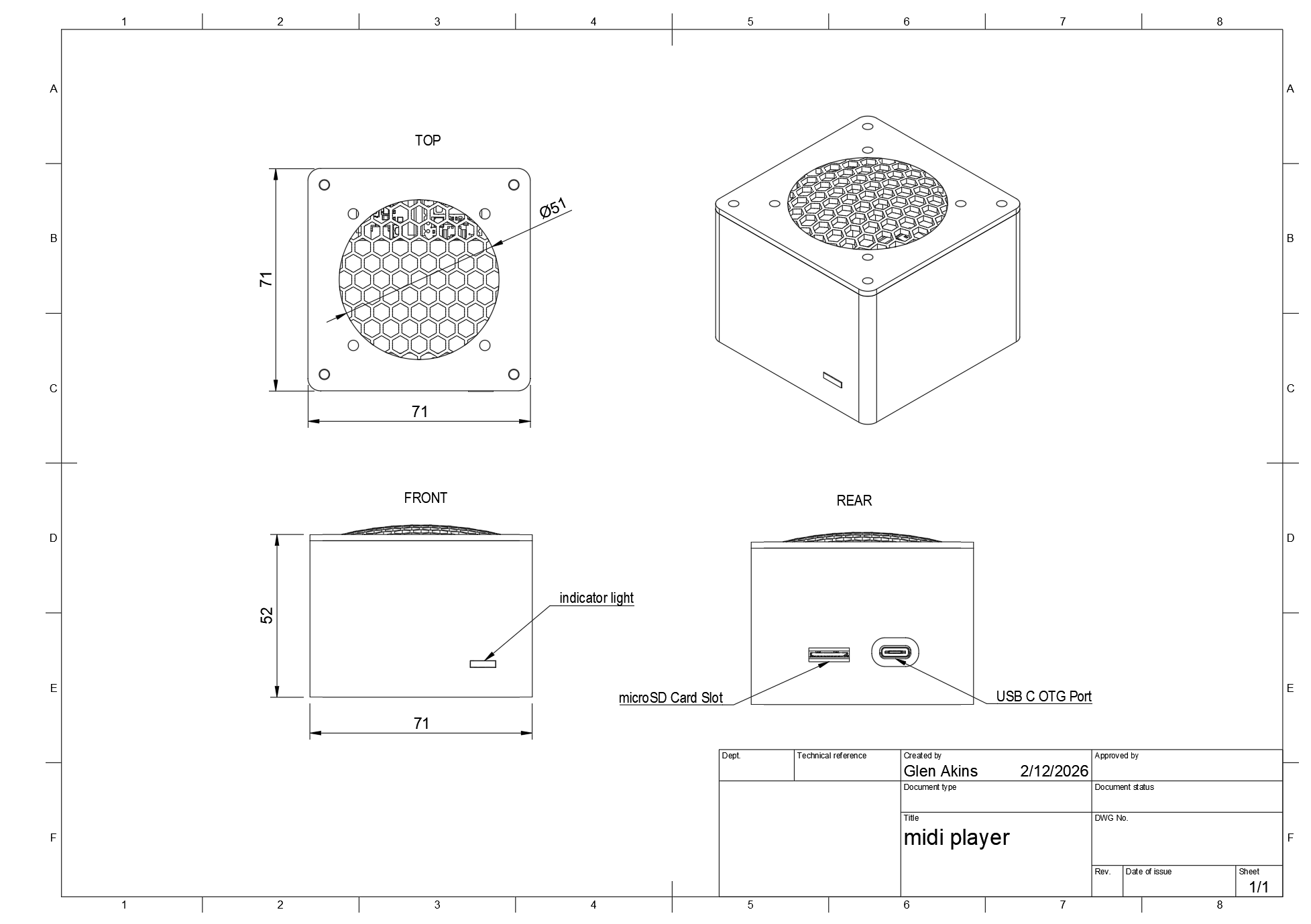
Dimensioned diagram of the speaker version.
A diagram of the enclosure is shown above. The enclosure measures 71 x 71 x 52 mm excluding the grill. On the front is a single LED to indicate the player is ready to play samples. On the rear of the enclosure is a microSD card slot and a USB C connector for power and the MIDI controller.
All three files in the speaker version enclosure directory need to be 3D printed as well as a single light guide. The .3mf files are configured for the Bambu Studio slicer for printing on a Bambu printer.
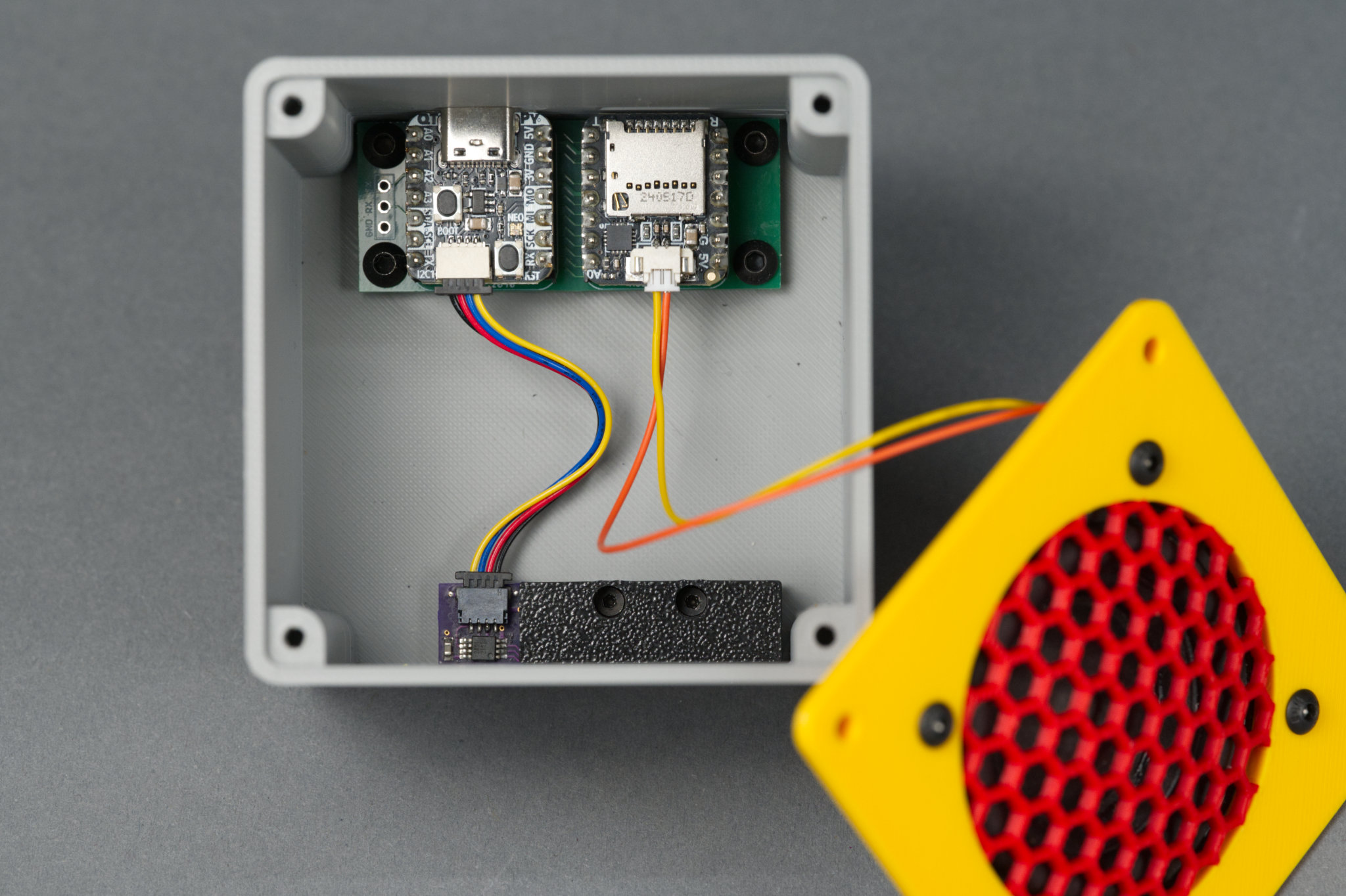
Inside view of the speaker version with all the electronics.
Once the files are printed, the main board is held in place using 4 M3 x 4 mm screws. The LED board and light guides are held in place using the led cover and 2 M2 x 6 mm screws. The speaker is held in place on the lid using 4 sets of M3 x 8 mm screws, M3 washers, and M3 hex nuts. Finally the lid is held in place using 4 M3 x 8 mm screws.
Line Out Version
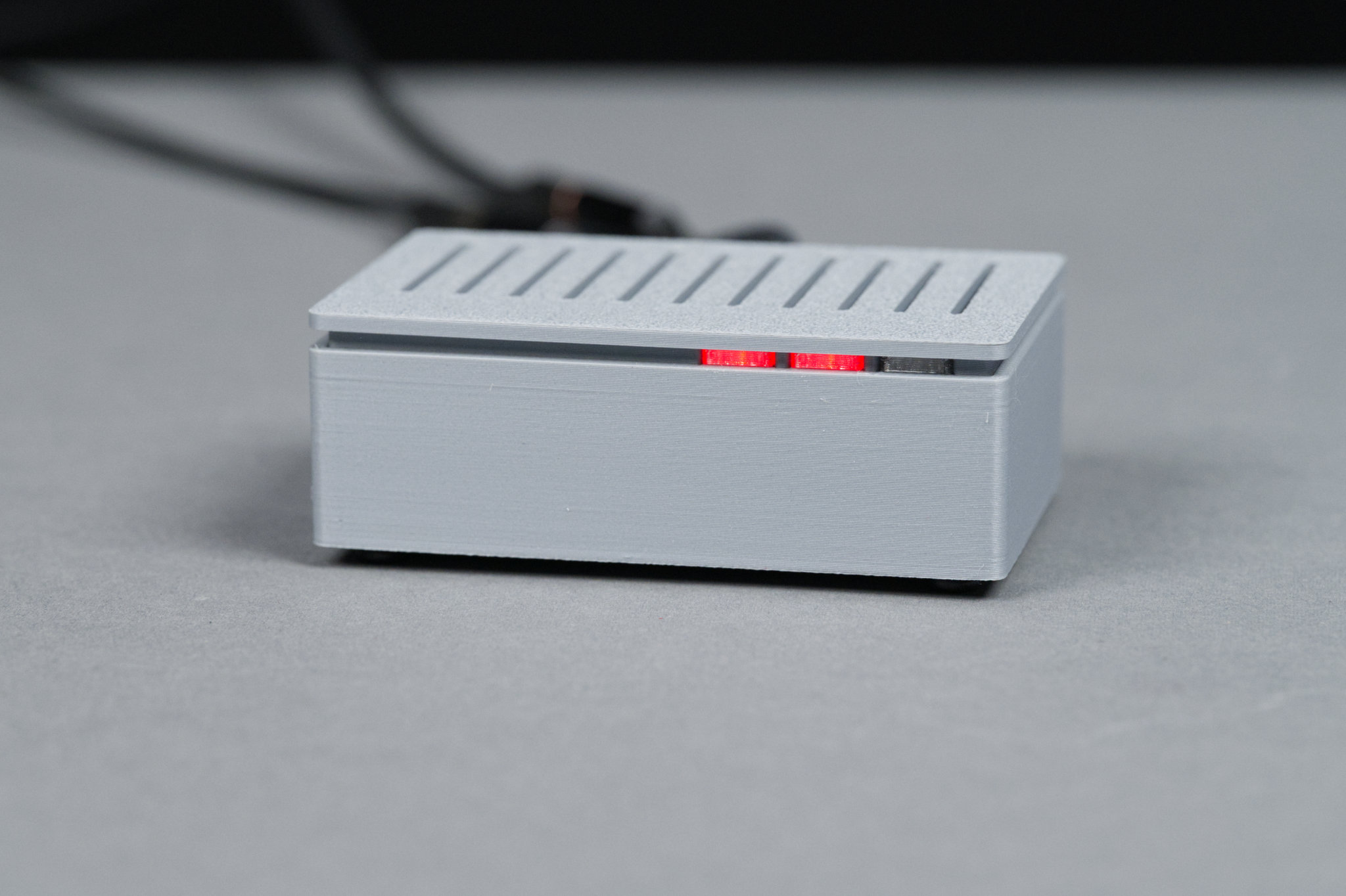
Front view of the line out version.
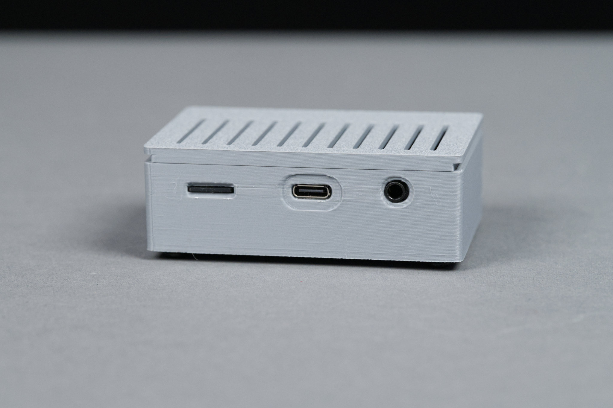
Rear view of the line out version.
The line out version’s enclosure is shown in the photos above. This enclosure design was inspired by the PiSCSI Mini Case. It’s smaller and its features have been made slimmer to better match its smaller size.
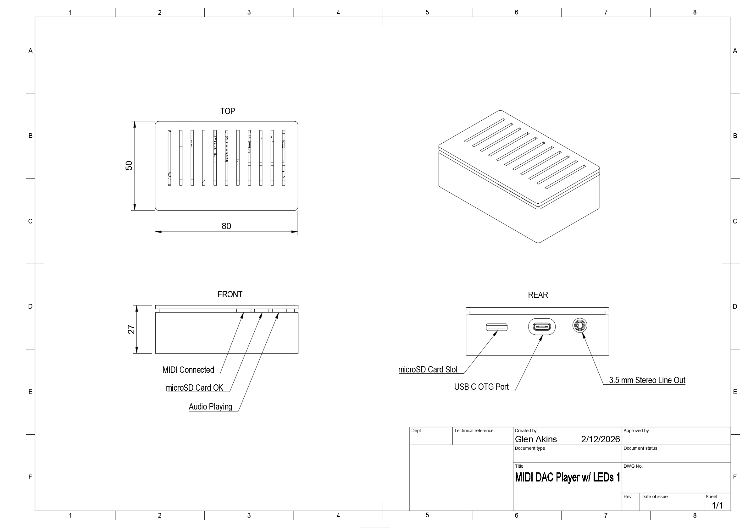
Dimensioned diagram of the line out version.
A diagram of the enclosure is shown above. The enclosure measures 80 x 50 x 27 mm. On the front are three status LEDs to indicate a MIDI controller is connected, the microSD card is mounted, and whether audio is playing or not. If the code is compiled for a single status LED, the left two LEDs will remain off and the right-most LED will simply indicate the player is ready to play samples. On the rear of the enclosure is a microSD card slot, a USB C connector for power and the MIDI controller, and a 3.5 mm stereo audio jack.
All three files in the line-out version enclosure directory need to be 3D printed as well as three light guides. The .3mf files are configured for the Bambu Studio slicer for printing on a Bambu printer.
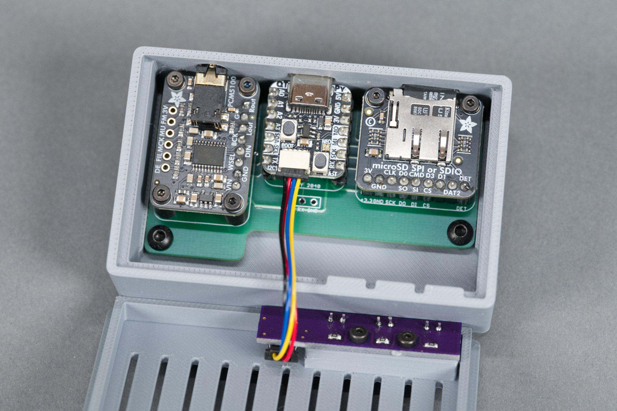
Inside view of the line out version.
Once the files are printed, the main board is held in place using the slots and guides inside the enclosure and 2 M3 x 4 mm screws. The LED board and light guides are held in place using 2 M2 x 4 mm screws. The lid is a simple friction fit. The 7.8 mm standoffs go between the daughter boards and the main board and are held in place using 12 M2 x 4 mm screws.
Connecting Power and the MIDI Controller
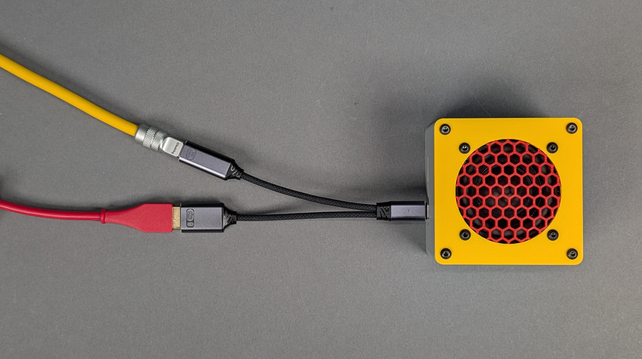
How to connect and power the projects. Yellow cable is power from a USB wall adapter, red cable goes to the MIDI controller, OTG adapter plugs directly into the project.
Power and the MIDI controller are connected to the project using a USB C OTG with power adapter cable:
- The male USB C connector on the OTG adapter plugs into the back of the project.
- The male USB A connector from the MIDI controller plugs into the female USB A connector on the OTG adapter. This is the red cable in the photo above.
- The male USB C connector from the power brick plugs into the female USB C connector on the OTG adapter. This is the yellow cable in the photo above.
The photo above shows these connections. Using an OTG adapter saves having to have a separate USB C or DC barrel jack on the back of the project which greatly simplified the board and enclosure design.
Bonus: 3D Printed Stands for the MIDI Controllers!
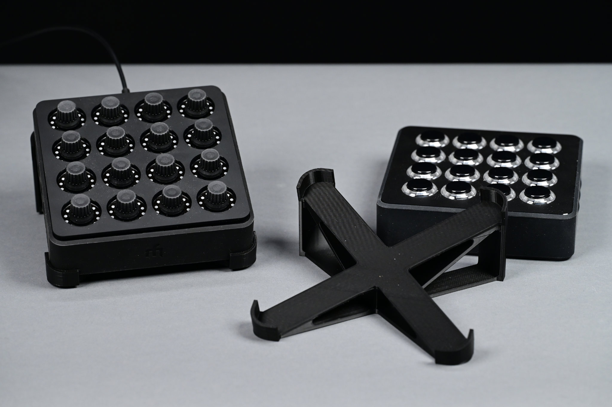
A Midi Fighter Twister on a 3D printed stand, a 3D printed stand, and a Midi Fighter Spectra lying flat on the bench.
If you need a stand for the Launchpad Mini Mk3, this 3D printable stand for it on Thingiverse is pretty nice. If you need a stand for the Midi Fighter Twister or Midi Fighter Spectra, I designed a similar 3d printable stand for them. The files for my stand are in the case/midi-fighter-stand directory of this project’s GitHub repository. The same stand works for either Midi Fighter controller.
Design Files
The source code, PCB design files, and 3D print files for this project can be downloaded at https://github.com/bikerglen/rp2040-midi-player.