
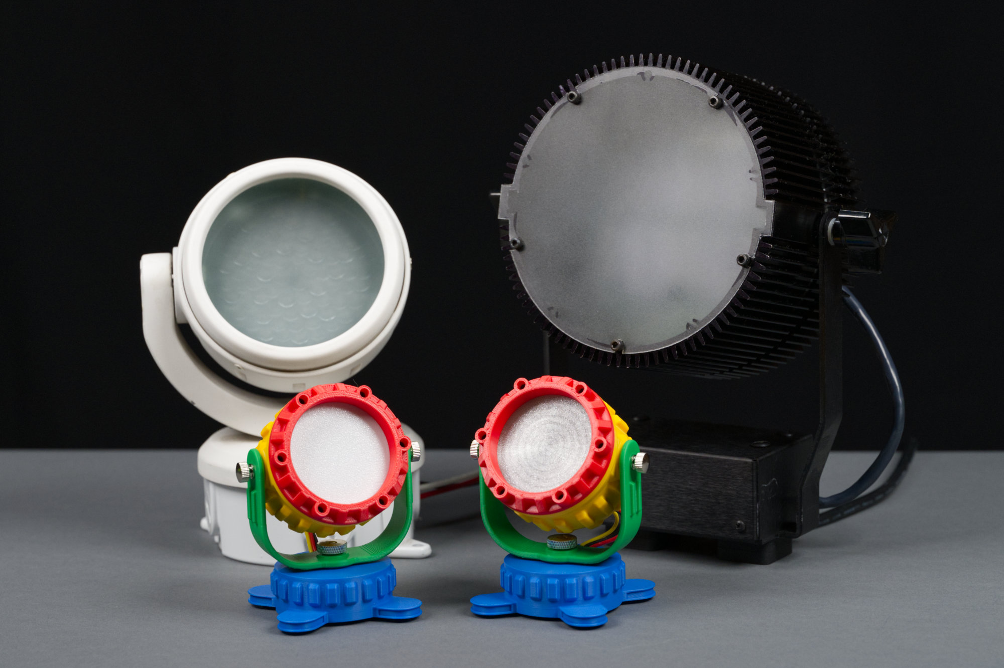
A white Color Kinetics ColorBlast 4, a black Color Kinetics C200, and two super-colorful My First Neopixel dance party lights.
Inspired by various colorful and chonky kids toys and some old Color Kinetics architectural fixtures, this colorful Neopixel spotlight packs an Adafruit Sparkle Motion Mini into its base and can be controlled over Wi-Fi using your choice of development environments. Read on to learn how to 3D print and build your own to bring a bit of colorful light into your work or living space!
Motivation
In the background is the original floodlight with the real 4.5″ Fresnel lens and a white plastic diffuser. In the foreground are two of the My First Neopixel Party Lights.
I found this old 4.5″ clear Fresnel lens on eBay and decided I wanted to incorporate it into a spotlight. I found a model I liked online, but it was the wrong size, did not have adjustable pivots, had a restrictive license agreement, and was only available as an STL mesh. It also only had room for a simple 60mm diameter puck light like those used for undercabinet lighting. I wanted to use a large Neopixel ring so it could change colors and I wanted room for the electronics inside the light.
I decided to make my own parameterized model instead. The result is shown in the photo above. It works but the model is pretty boring overall. Why was I always printing so much stuff in black filament when I had an entire shelf of colorful filament? And just how well did I parameterize things? How small could I make the model? What would break as I adjust the size downward? Could I make something without requiring an obscure and expensive Fresnel lens?
Then I remembered all those super colorful Little Tikes and Fisher Price My First toys, and more importantly, the parodies of those toys like the Little Tikes My First Cubicle Playset, the Fisher Price Seance Playset, and the Soul Crushing Meeting Playset. And the project idea was born: could I make my Neopixel spotlight smaller, eliminate the need for an obscure lens, and more importantly, colorful and fun looking?
About the Design
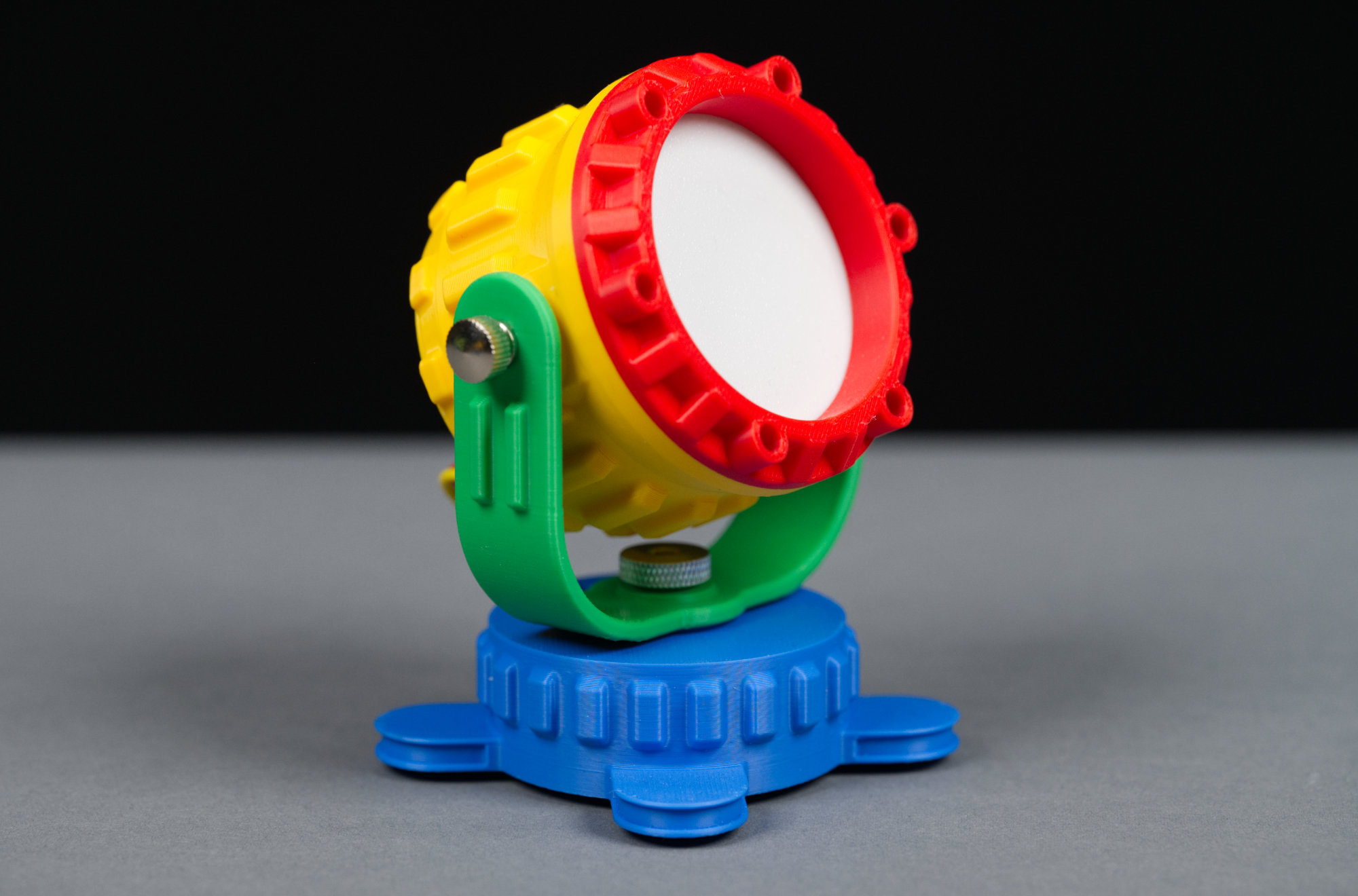
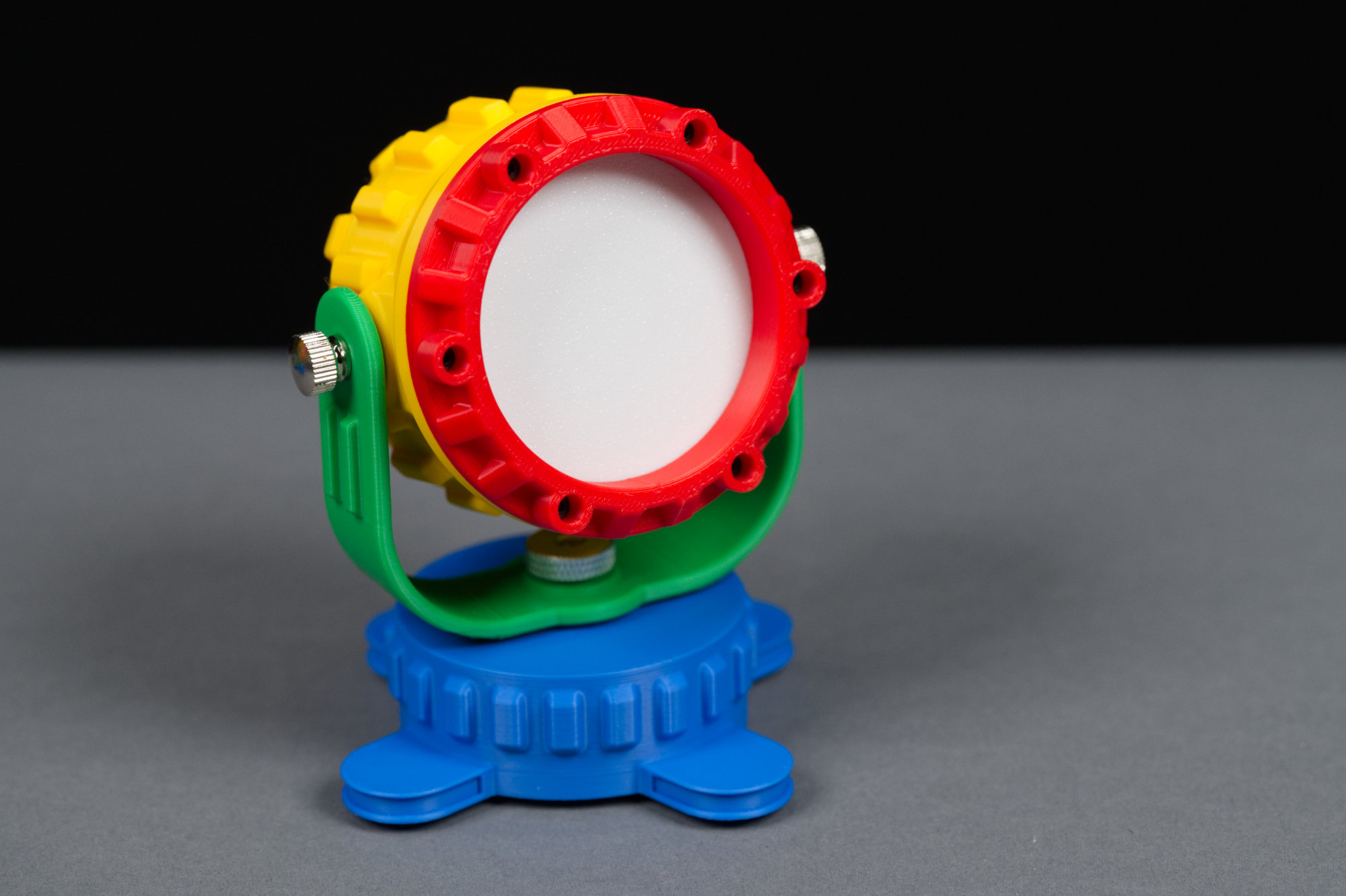
A close up of the finished fixture.
The photograph above shows the final version of the My First Neopixel Party Light. It’s printed from four colors and black and white filament. Everything is 3D printed except the metal hardware. It consists of a red retaining ring that holds a white plastic light diffuser on to a yellow body. The yellow body is connected to a green yoke that’s connected to a blue base. It has faux heatsink fins all around resembling the C200 wash light’s heat sink and a round base for the electronics resembling the round electrical box attached to the bottom of the ColorBurst 4 light.
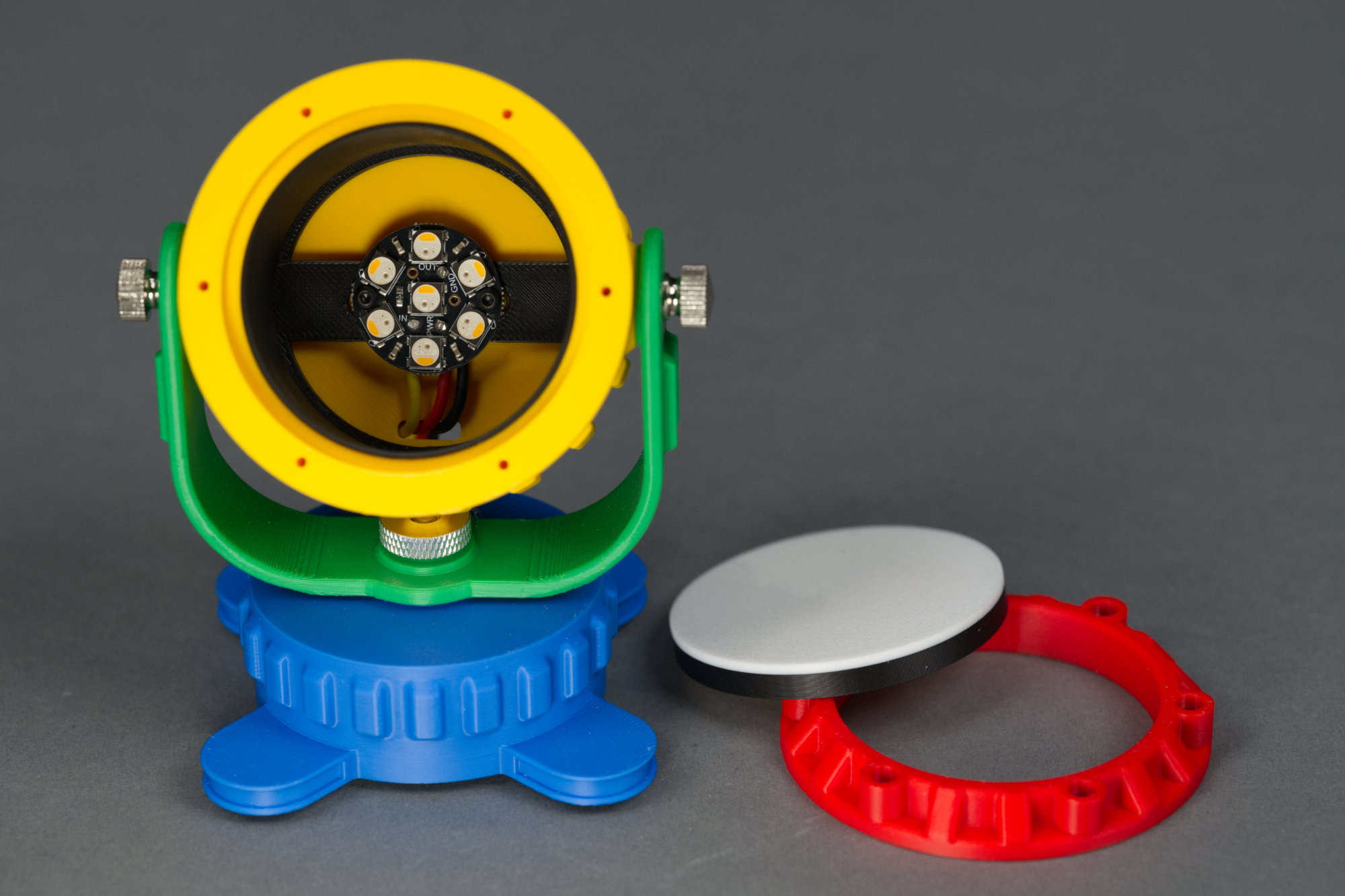
Inside the main body of the fixture is room for an Adafruit Neopixel Jewel 7. There’s also a black shield to prevent light from the LEDs spilling through the. yellow plastic of the main body.
Inside the yellow body are a black plastic light shield and an Adafruit Neopixel Jewel 7 with seven RGBW Neopixel LEDs. The light shield keeps the light from the LEDs from shining through the yellow body. The Neopixel Jewel is held in place using two small screws.
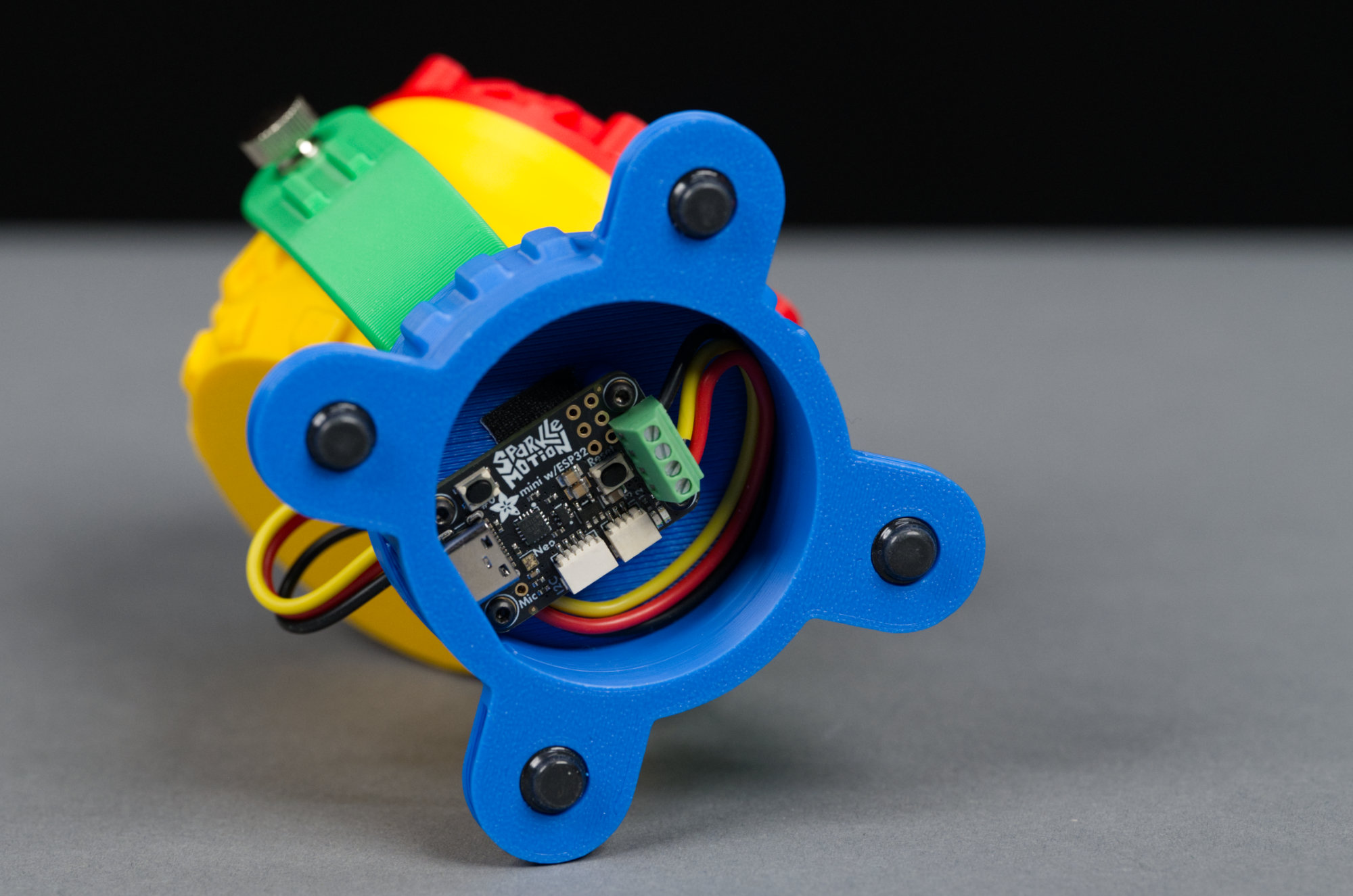
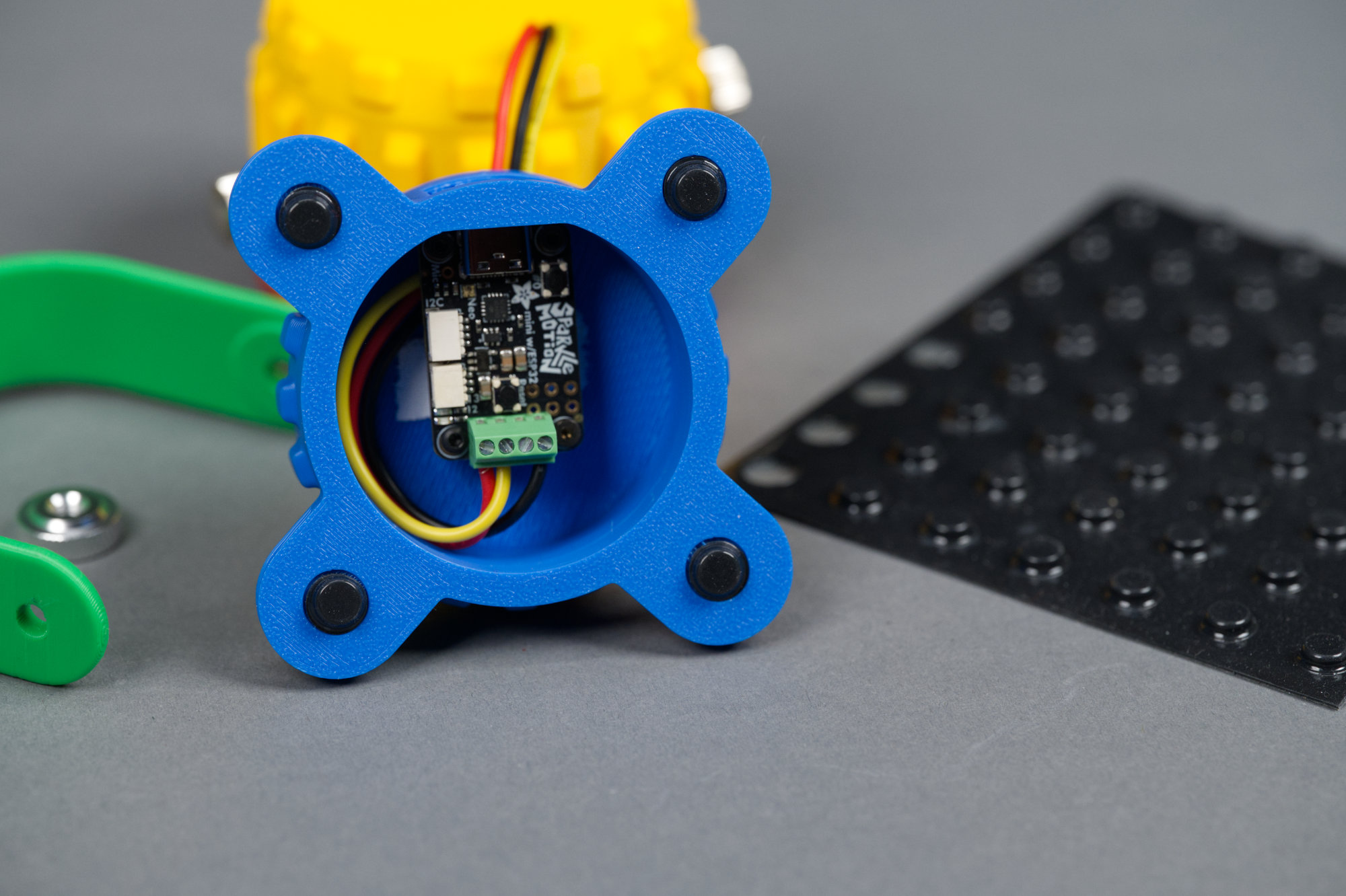
Inside the base of the light is room for an Adafruit Sparkle Motion Mini.
On the bottom of the base are four rubber sticky feet. Inside the base is a space to mount an Adafruit Sparkle Motion Mini. The Sparkle Motion Mini is held in place using four small screws.
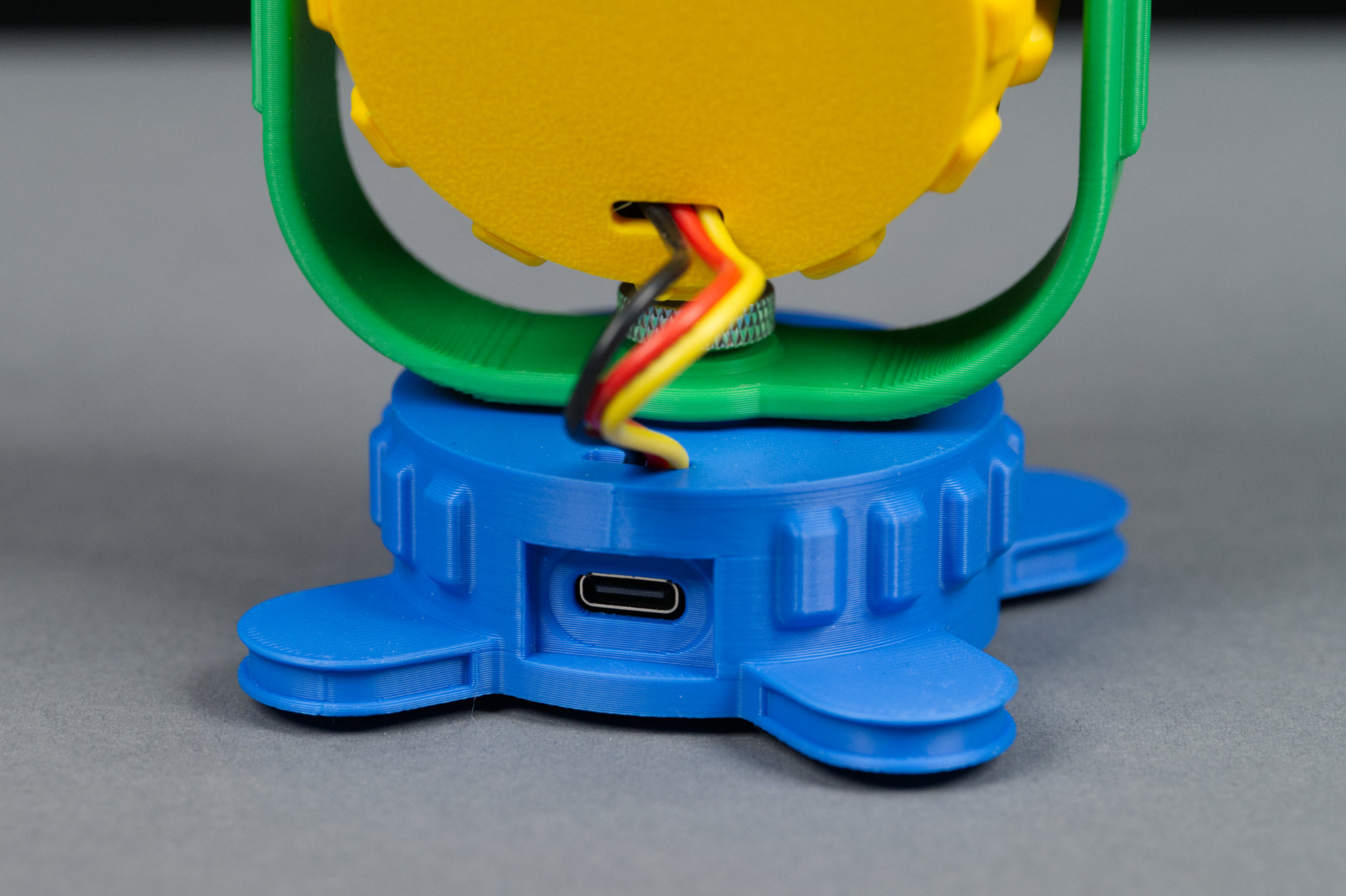
The Adafruit Sparkle Motion Mini’s USB C port pokes through an oval hole on the back of the fixture.
The Sparkle Motion Mini’s USB 2.0 Type C connector is accessible through a cutout on the rear of the base.
CAD Model
The completed CAD model. The Fusion base opaque plastic appearance was duplicated,, set to the official Bambu Lab RGB colors, and applied to each body in the model.
The image above shows a render of the completed Autodesk Fusion 3D model. The completed model is an assembly of smaller 3D models contained in separate files. To see the parameters associated with each part of the design, you’ll need to dive into each file.
If you change.a parameter, you’ll need to hop back to the completed assembly and update the linked model to see the changes to the overall model. A brief description of the parameters appears at the end of this post. All the files include the full design history as well so what isn’t parameterized can still be edited.
The completed My First Neopixel Party Light.
I used the Fusion appearance tool to give each part of the model an opaque plastic appearance. The color of each unique appearance in the model was set to the Bambu Lab official filament RGB values for that color. The video above shows how close a match the render colors are to the 3D printed parts’ colors.
Electronics
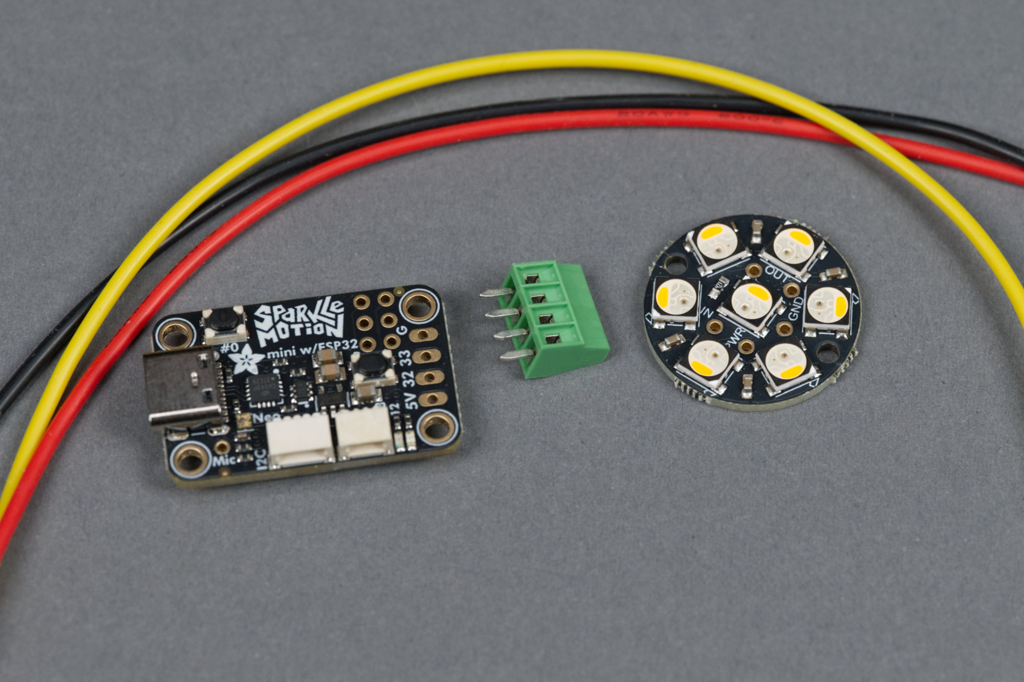
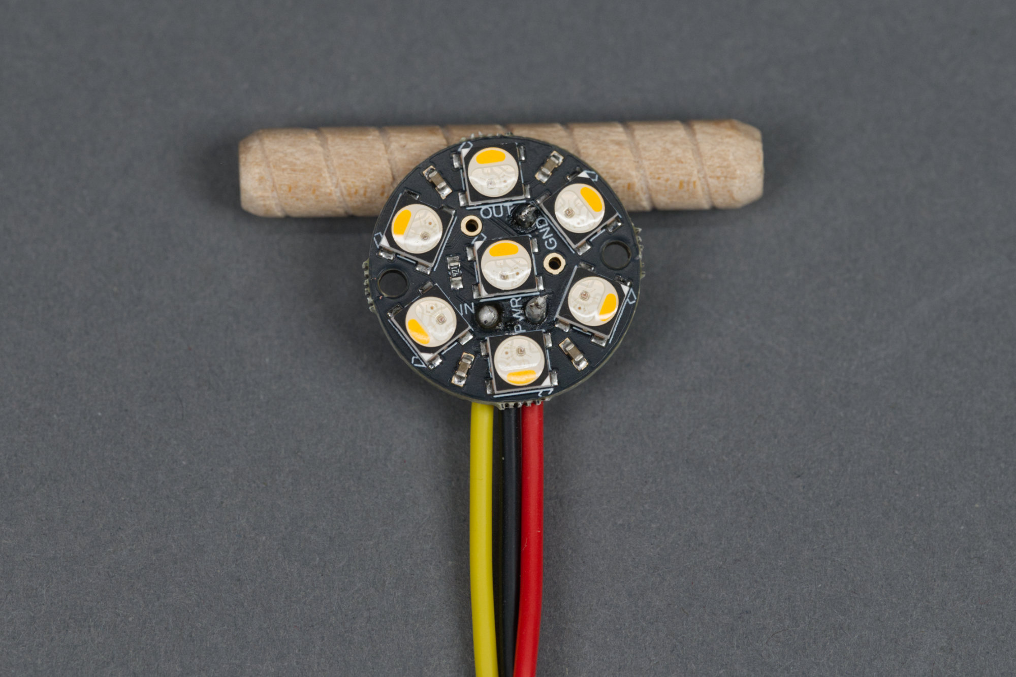
The electronics for this project consist of an Adafruit Sparkle Motion Mini, an Adafruti Neopixel Jewel 7, and three strands of wire.
The electronics for this project are minimal: a board with some Neopixels, a board to control the Neopixels, and some wire. Soldering the wires onto the Neopixel Jewel is the hardest part of the project because there just isn’t really a lot of room for error when trying to reach the solder pads with the soldering iron while avoiding melting the LED housings. Pin outs and connections are shown in the Assembling the Design section of this post.
Bill of Materials
The complete bill of materials for the project is listed in the table below. The exact filaments I used are listed in the next section. If you have a local Do It Best or ACE Hardware, almost all the hardware for this project can be purchased by the piece there and for far less money than ordering online.
| Qty | Description | Supplier 1 | Supplier 2 |
|---|---|---|---|
| 1 | Adafruit Sparkle Motion Mini | Adafruit | DigiKey |
| 1 | Adafruit Neopixel Jewel 7 x 5050 RGBW | Adafruit | DigiKey |
| 1 | M4 x 12 mm External Hex Head Bolt | McMaster | Amazon |
| 1 | M4 Knurled Thumb Nut | McMaster | Amazon |
| 2 | M4 Hex Nuts | McMaster | Amazon |
| 2 | M4 x 10 mm Knurled Thumb Screws | McMaster | Amazon |
| 6 | M2 x 4 mm Screws | McMaster | Amazon |
| 6 | M2 x 6 mm Screws (Black Oxide Steel) | McMaster | Amazon |
| 4 | 0.315″ Diameter Rubber Feet | — | DigiKey |
| — | Stranded Hookup Wire | Adafruit | DigiKey |
| — | Soldering Iron and Solder | — | — |
| — | 3D Printer and Filament | — | — |
Disclaimer: The Amazon links above are affiliate links and Glen may earn compensation for sales from these links through an affiliate program. The other links are not part of any affiliate program.
Printing the Design
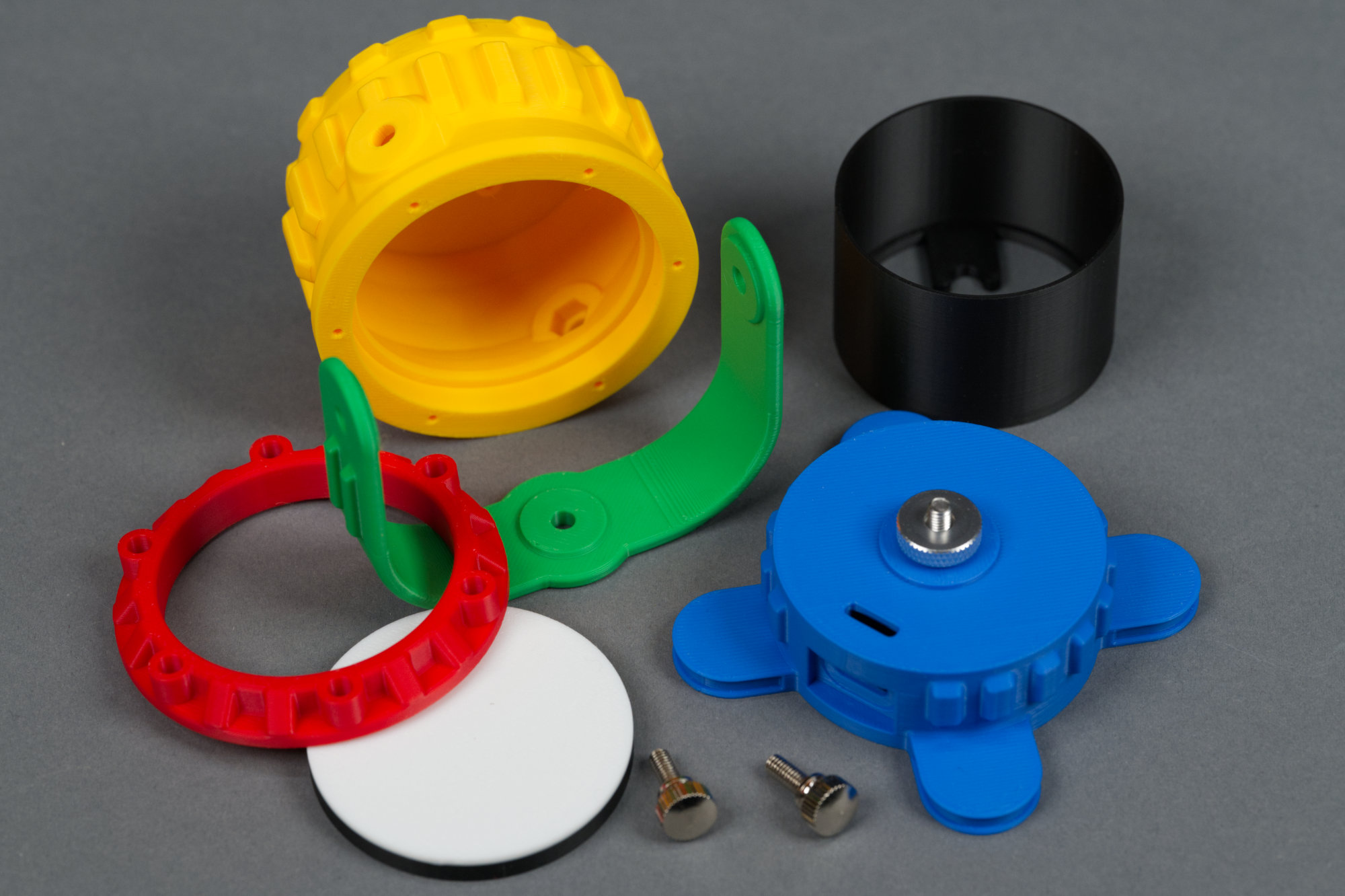
All the 3D printed parts for the project plus some of the hardware required for assembly.
The ready-to-print Bambu Studio 3MF files for this design can be downloaded by clicking the links in the table below. The table also lists the filaments I used and the print times on a Bambu X1C. The base and yoke require support. The rest of the design can be printed without support. I did not use any specialized support or support interface material for this design. The Autodesk Fusion archive files can be download in the Modifying the Design section at the end of this post.
| Part | Description | Download File | Filament | Print Time |
|---|---|---|---|---|
 |
Base | blue_base_for_sparkle_motion_mini.3mf | Cobalt Blue | 1h11m |
 |
Yoke | green_yoke.3mf | Bambu Green | 39m |
 |
Housing | yellow_housing_for_neopixel_jewel.3mf | Sunflower Yellow | 1h04m |
 |
Retaining Ring | red_retaining_ring.3mf | Red | 24m |
 |
Liner | black_liner.3mf | Black | 22m |
 |
Lens | white_diffuser_with_black_ring.3mf | Jade White and Black | 17m |
Assembling the Design
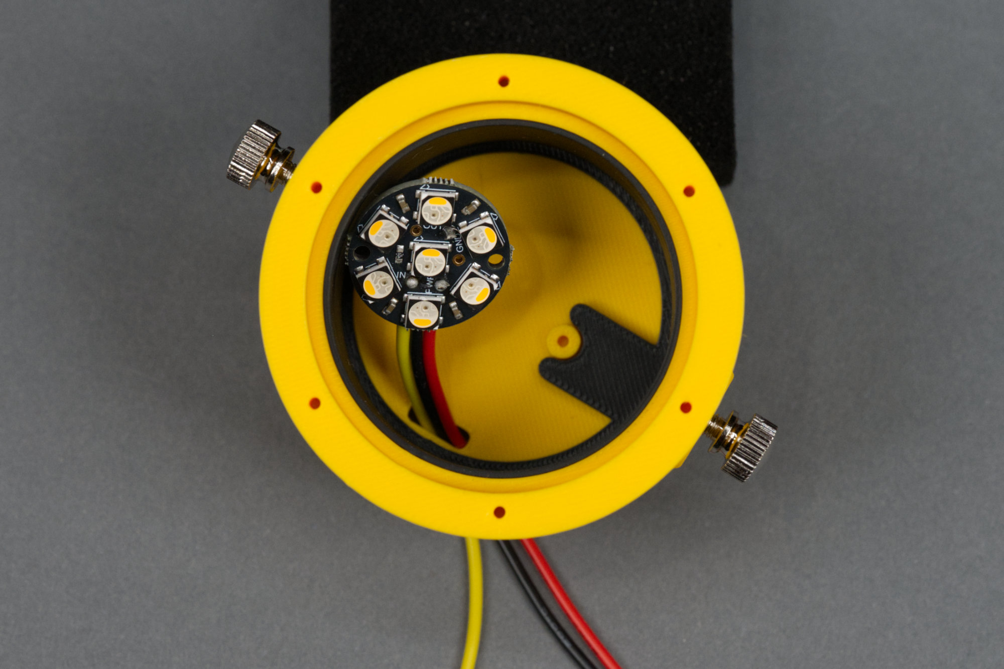
1) Solder power, ground, and data wires to the Neopixel Jewel
The Neopixel Jewel with red, black, and yellow wires soldered respectively to a VDD pad, a GND pad, and the data IN pad.
This is the toughest part of the project in my opinion. It’s tough fitting the soldering iron between the LEDs to reach the Jewel’s solder pads. It can be done but requires patience. Solder a red wire to one of the VDD pads, a black wire to one of the GND pads, and a yellow or third color wire to the IN pad. Solder the wires such that they leave perpendicular to a line through the mounting holes and all in the same direction. Leave about 8″ of wire extending from each pad.
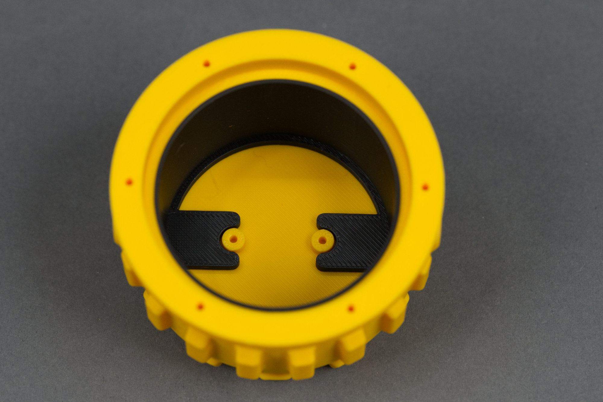
2) Place the two M4 nuts in their cavities on the inside of the upper housing.
One of two M4 nuts placed inside the yellow main body of the fixture.
Place the nuts in their cavities on the inside of the yellow body. It’s a tight fit. If you have bigger hands, it might be helpful to thread one of the M4 thumbscrews into them then pull them into position from the outside of the body.
3) Place black light shield into the upper housing.
Light shield placed inside the yellow body.
Place the black light shield inside the yellow housing. The black tabs align with the mounting studs for the Neopixel Jewel. Without the shield, the light from the Neopixels will shine through the yellow body of the fixture. The Jewel will eventually hold the retaining ring in place.
4) Temporarily thread the M4 thumb screws into the M4 nuts.
Thread the thumbscrews into the nuts.
There’s still a bit of a gap between the M4 nuts and the light shield so threading the thumbscrews loosely into the nuts will prevent them from falling out of place during the rest of the assembly steps.
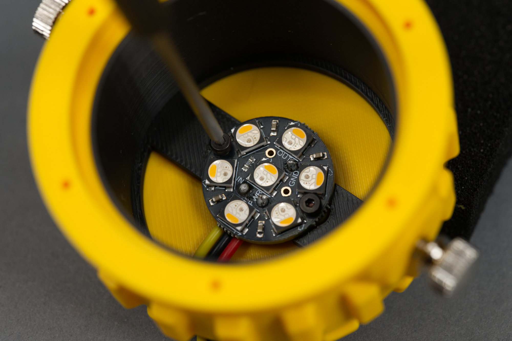
5) Thread Neopixel Jewel wires through the slot on the bottom of the upper housing.
Thread the wires down and through the slot in the bottom of the body.
Thread the wires through the slot in the bottom of the body. The ordering doesn’t matter as long as they lay kinda flat in the body.
6) Secure Neopixel Jewel to the bottom of the upper housing using 2 of the M2 x 4 mm screws.
Using a small hex driver to install the 2nd of two M2 x 4 mm screws to hold the Neopixel Jewel in place.
Use a small hex driver or hex key and two M2 x 4 mm screws to install the Neopixel Jewel in the bottom of the body. Do not overtighten the screws. This step can be kinda tricky since the body is deep and the Neopixel Jewel is mounted at the bottom of the body.
7) Place diffuser into the upper housing with the white disc toward the outside.
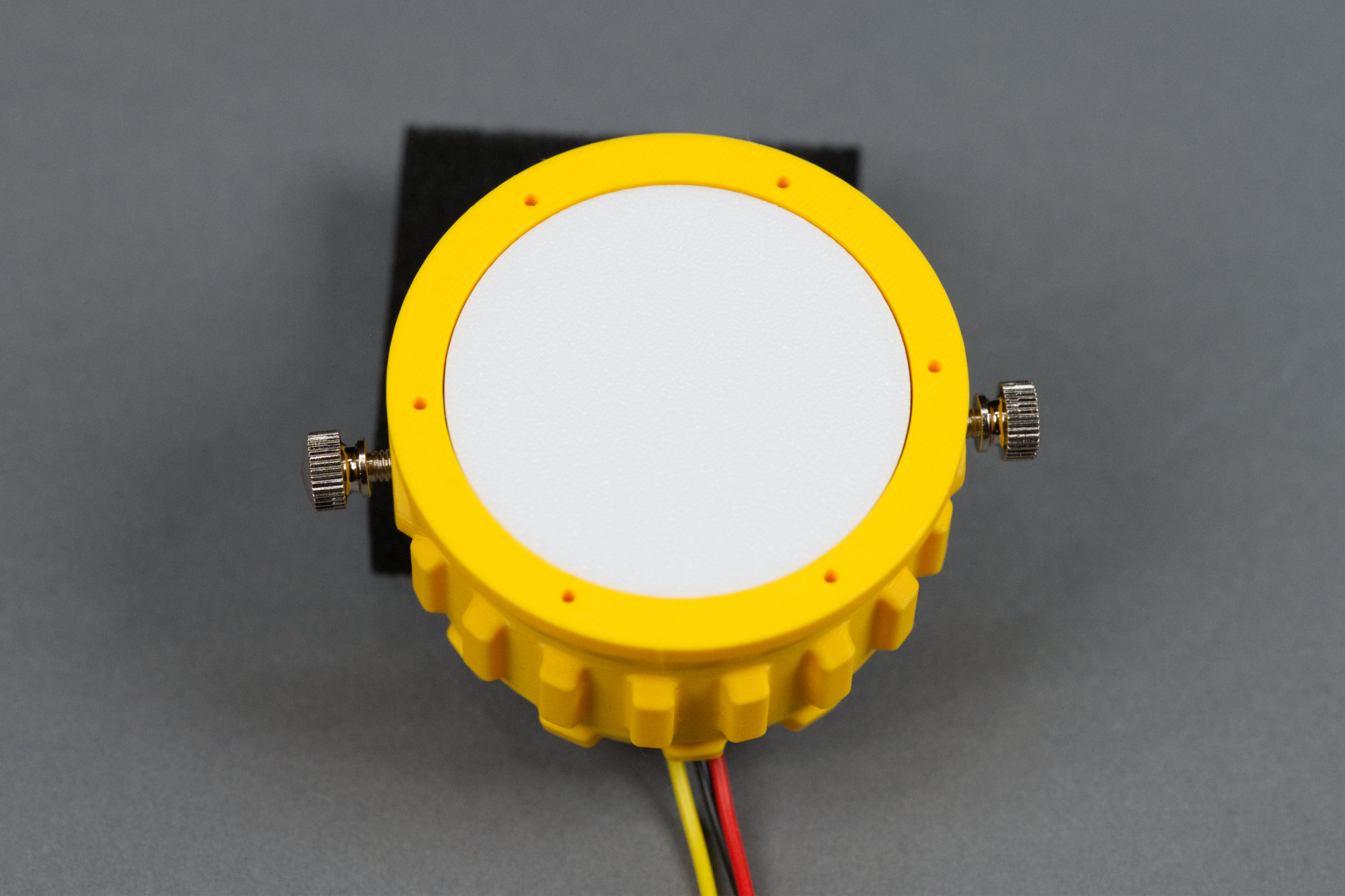
The diffuser installed in the body.
Place the diffuser with the black ring down / the white “lens” up into the body. It’s a loose fit.
8) Secure red retaining ring over the diffuser using the six M2 x 6 mm screws.
Red retaining ring secured over lens on body.
Use the six M2 x 6 mm screws to secure the red retaining ring over the lens and body. Again, be careful not to overtighten.
9) Place the M4 x 12 mm hex bolt in its cavity in the bottom housing.
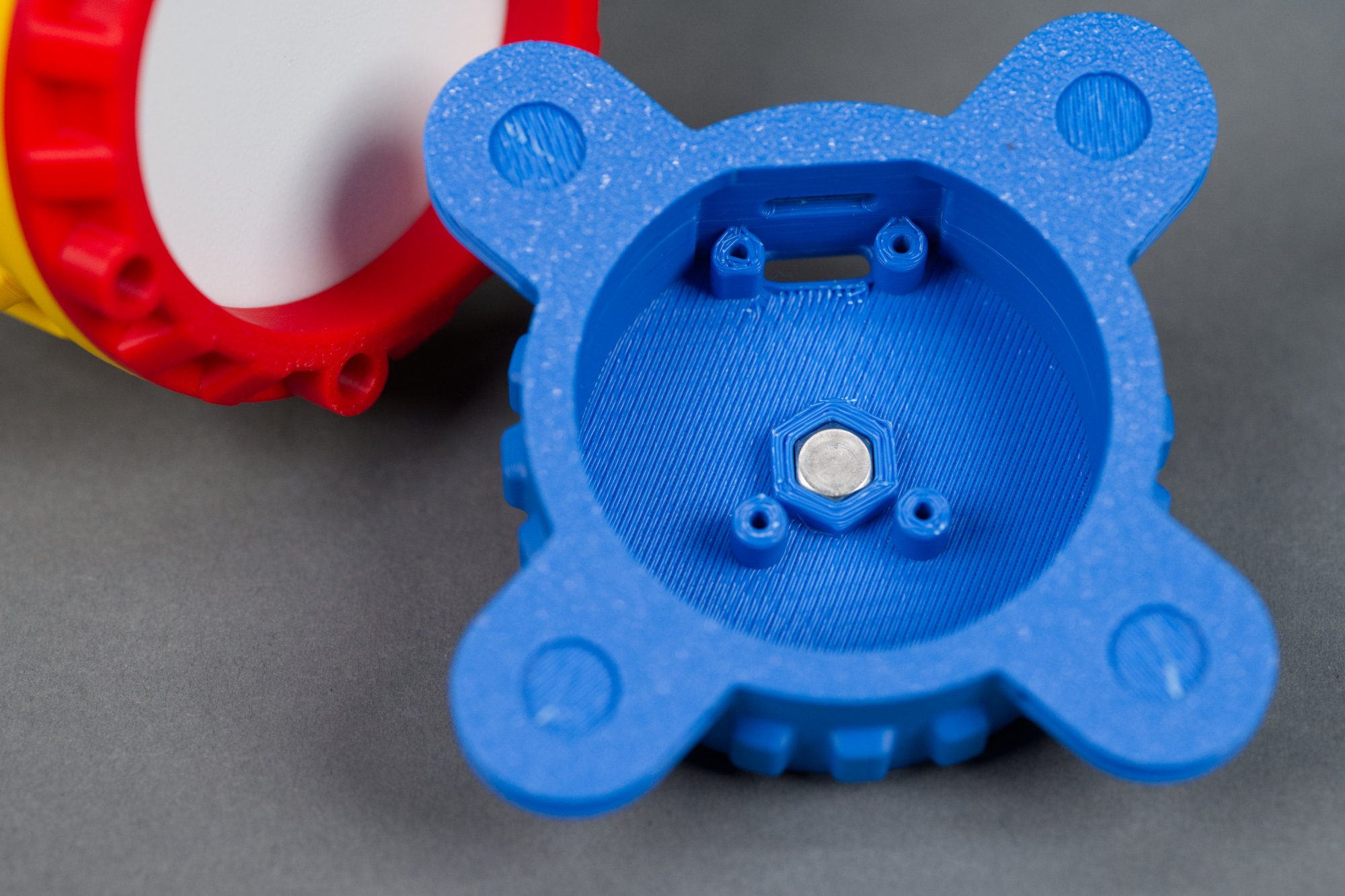
M4 x 12 mm bolt loosely placed in base.
Place the M4 x 12 mm hex bolt in its cavity in the bottom housing.
10) Place a small piece of tape over the hex bolt to hold it in place.
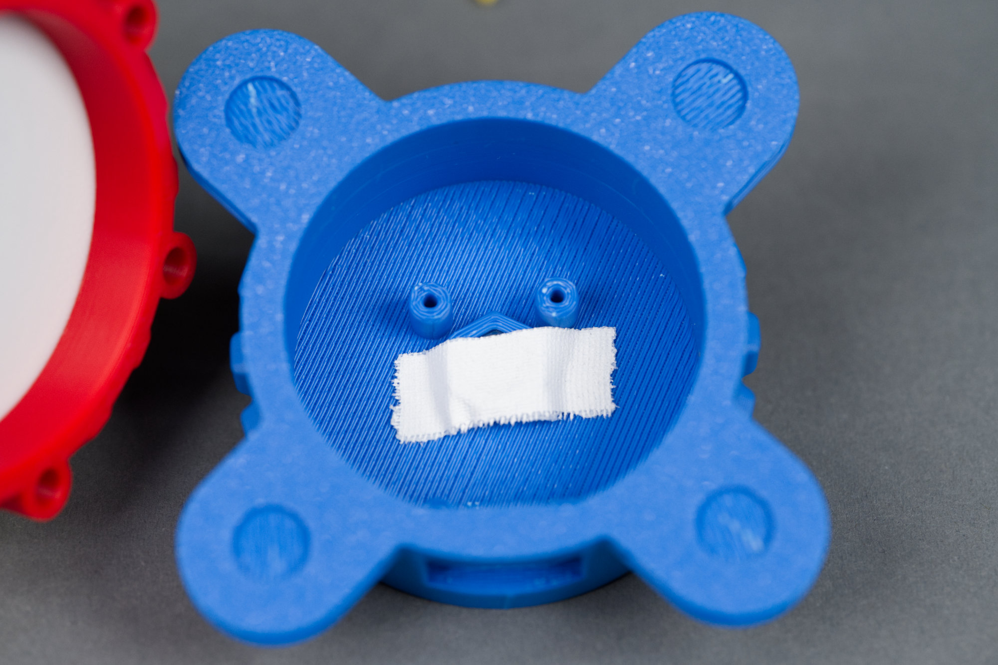
Some white gaffer’s tape over the head of the bolt in the housing.
Place a small piece of tape over the head of the bolt in the base of the housing. This will keep the bolt from falling out until the light is completely assembled. It’ll also prevent the bolt from shorting into the Sparkle Motion Mini if it is inadvertently loosened later.
11) Thread wires through the slot on the bottom housing and connect them to the Adafruit Sparkle Motion Mini.
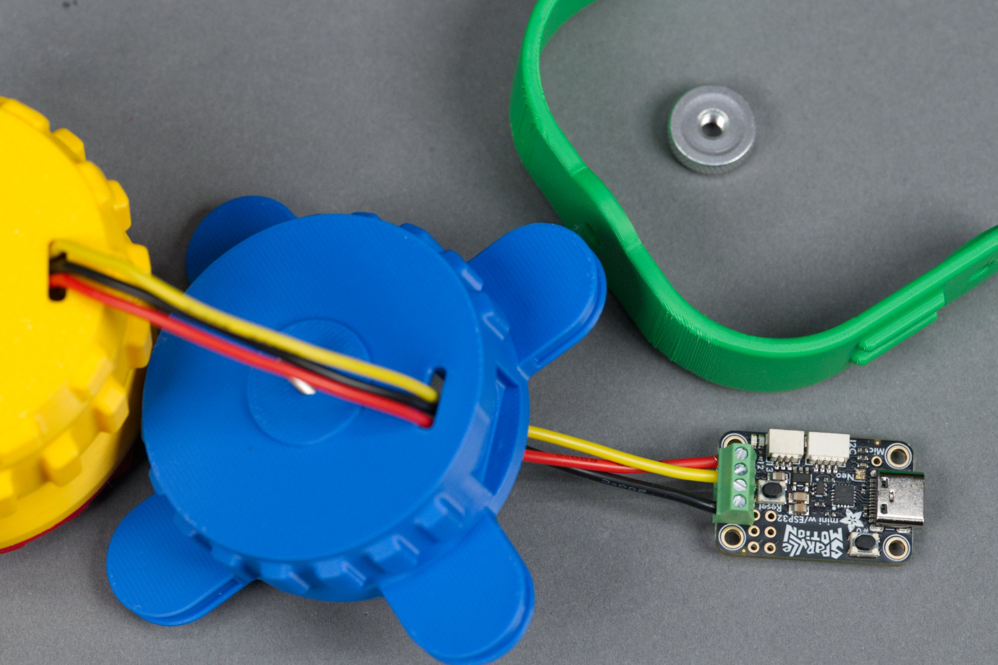
Wires routed from body through base and connected to the Sparkle Motion Mini.
Route the wires from the body through the base and to he Sparkle Motion Mini. Strip a few mm from each wire and connect them to the screw terminals on the Sparkle Motion Mini. Connect the red wire to the +5V terminal, the black wire to the GND terminal, and the data wire to the data terminal closest to the VDD terminal.
12) Arrange wires and secure the Sparkle Motion Mini in place using the last four of the M2 x 4mm screws.
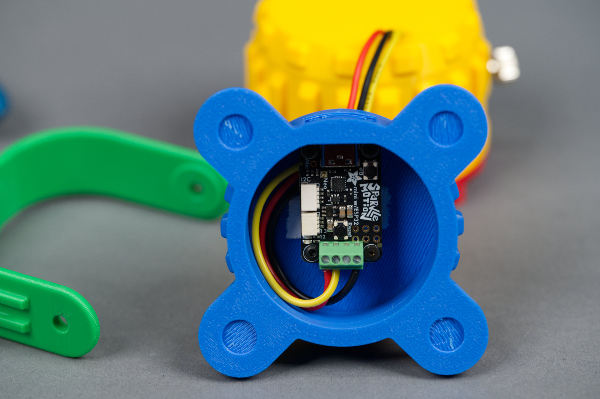
Sparkle Motion Mini secured in the base of the fixture.
Clear the inside of the base of any support material then place the Sparkle Motion Mini into the base. Be sure the Sparkle Motion Mini’s USB C port is accessible through the rear of the base. Secure the development board in place using the last four M2 x 4 mm screws.
13) Place four rubber sticky feet on the bottom of the base.
Rubber feet stuck to the base.
On the bottom of the base are four slight indentations for rubber feet. Make sure they’re clear of any support material then place a sticky rubber foot in each indentation.
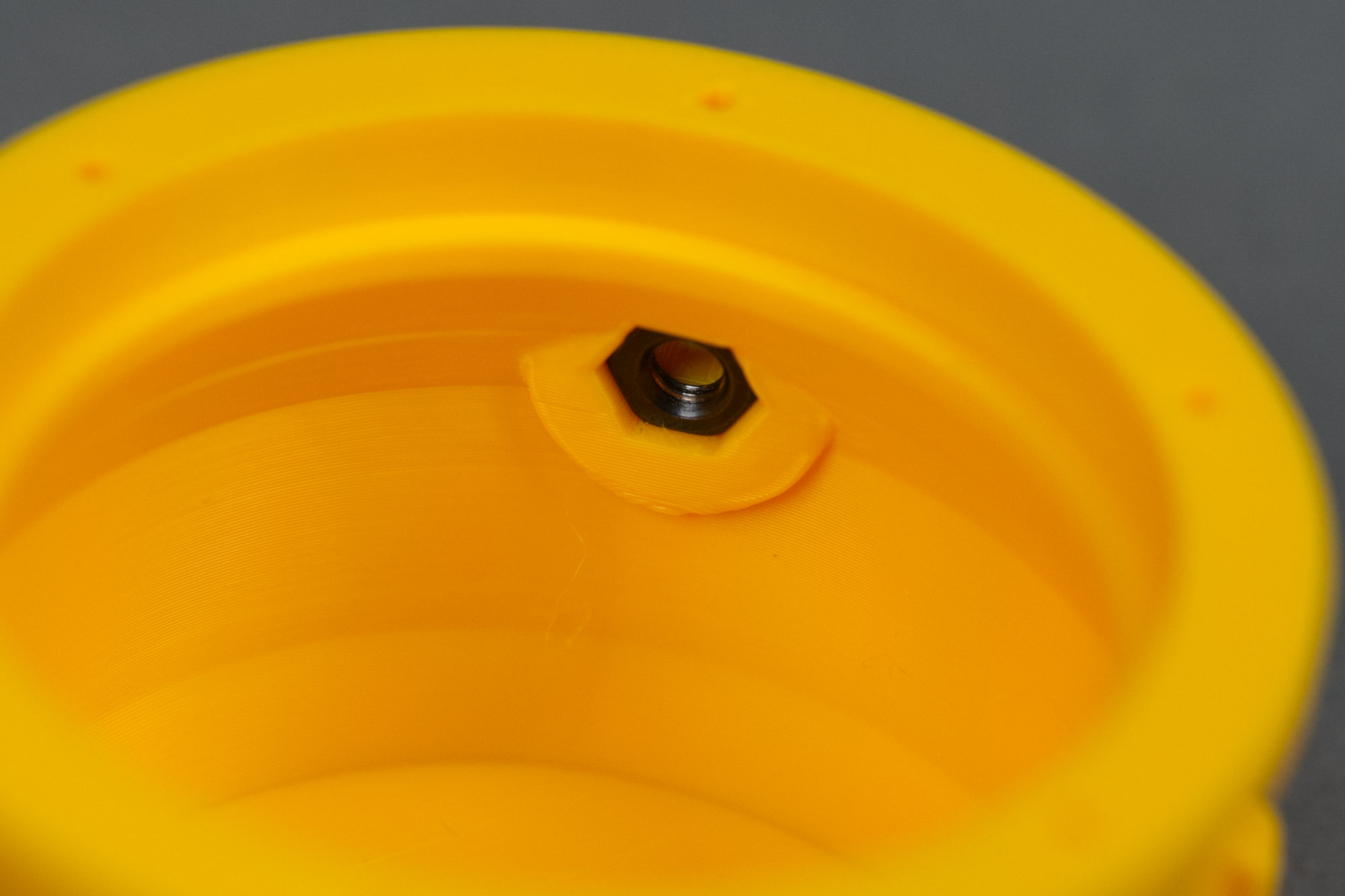
14) Place the yoke on the lower housing and secure it using the M4 thumb nut.
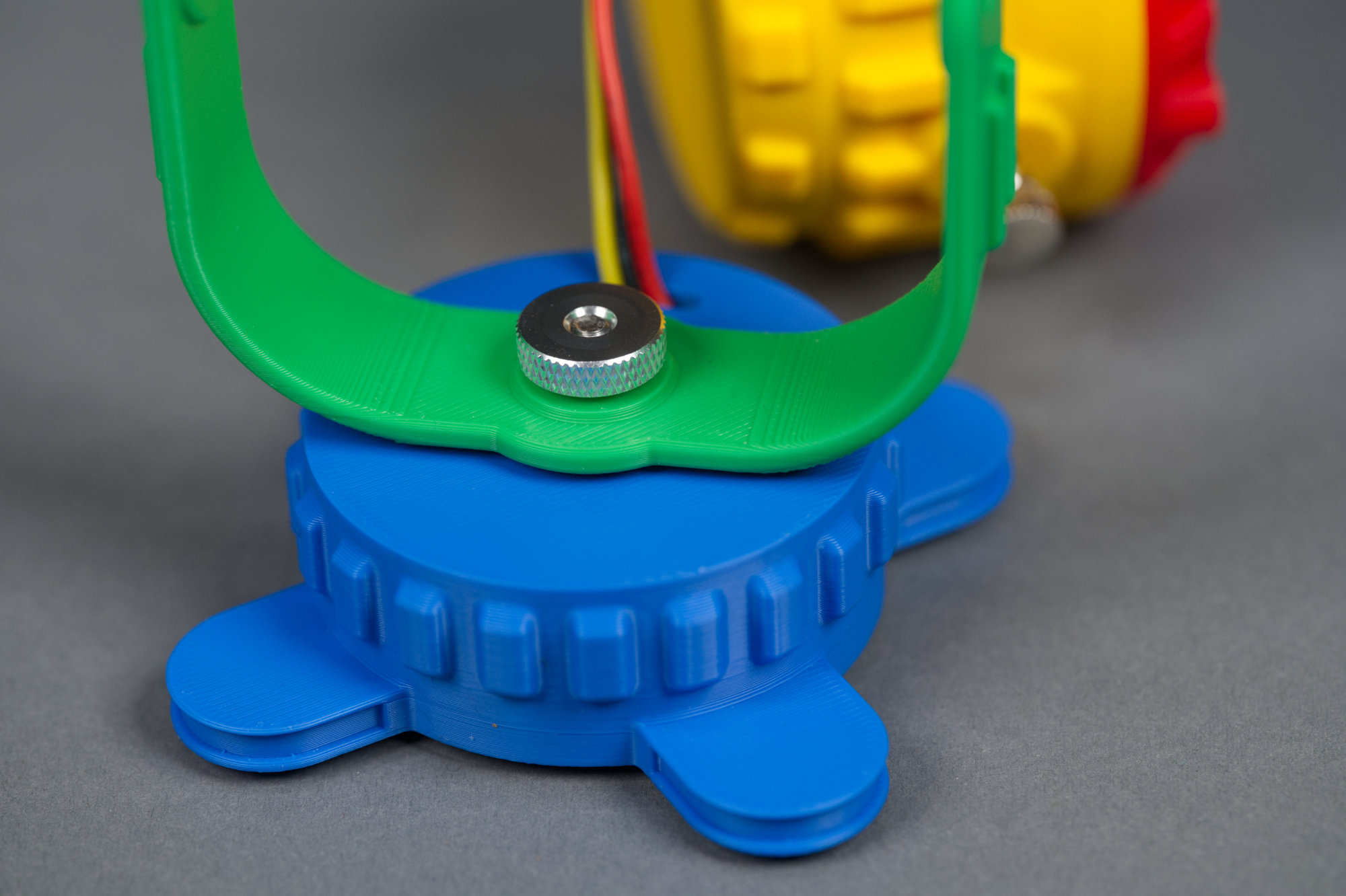
Yoke placed over hex bolt on base and secured with a thumb nut.
Place the yoke on the base over the protruding M4 bolt then secure the yoke in place using the M4 thumb nut.
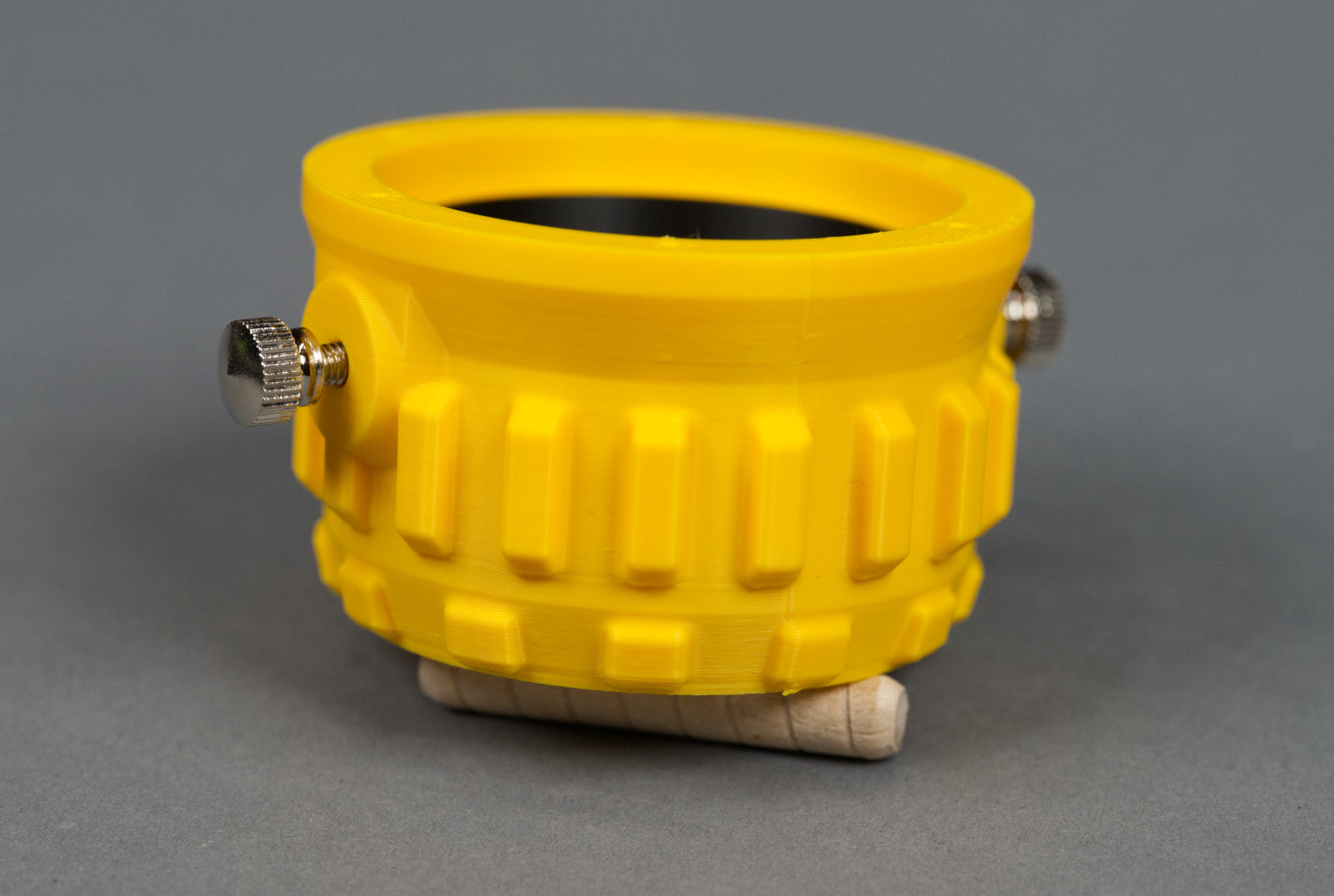
15) Remove the M4 thumb screws, place the upper housing in the yoke, and secure it in place using the thumb screws.
Congratulations! The fixture build is complete. Time to move on to the software.
Remove the M4 thumb screws from the yellow body, place the yellow body in the green yoke, and replace the M4 thumbscrews. This completes the mechanical assembly of the design.
Programming the Design
The My First Neopixel Party Light can be controlled using the popular WLED LED controller software or custom software can be developed to control it using CircuitPython or the Arduino development environments. I’d suggest reading through the following sections and reading the links to the official Adafruit documentation for the Sparkle Motion Mini and only then deciding how you want to control your light.
WLED
WLED doesn’t require any programming but the configuration and usage options can be overwhelming. If you want to jump right in without writing any software, this is the best option. The WLED setup guide is available at Adafruit Sparkle Motion Mini WLED Setup Guide. The LEDs are connected to GPIO 32.
CircuitPython
CircuitPython is usually easier than Arduino except that the Sparkle Motion Mini doesn’t have a native USB port which complicates matters. If you know Python or have used CircuitPython before, this may still be the simplest route. The CircuitPython setup guide is available at Adafruit Sparkle Motion Mini CircuitPython Setup Guide. The LEDs are connected to GPIO 32.
Arduino
If you’re familiar with C or Arduino, sticking with the Arduino development is likely the easiest path forward. The Arduino setup guide is available at Adafruit Sparkle Motion Mini Arduino Setup Guide. The LEDs are connected to GPIO 32.
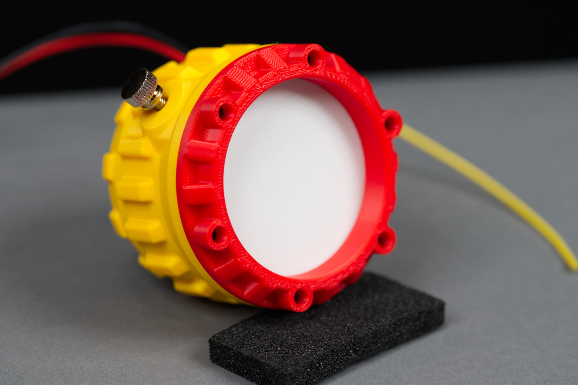
Alternative Lens Design
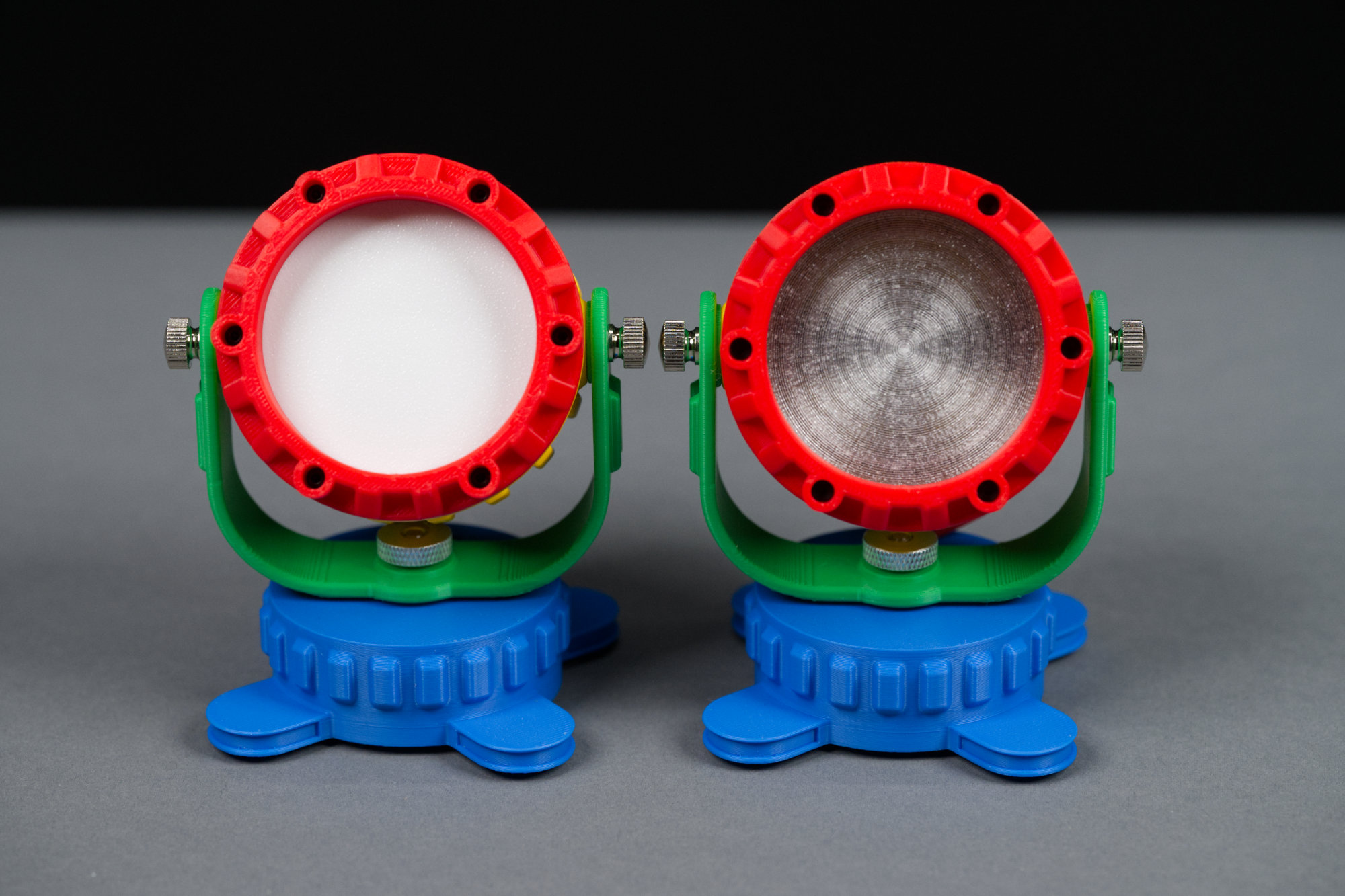
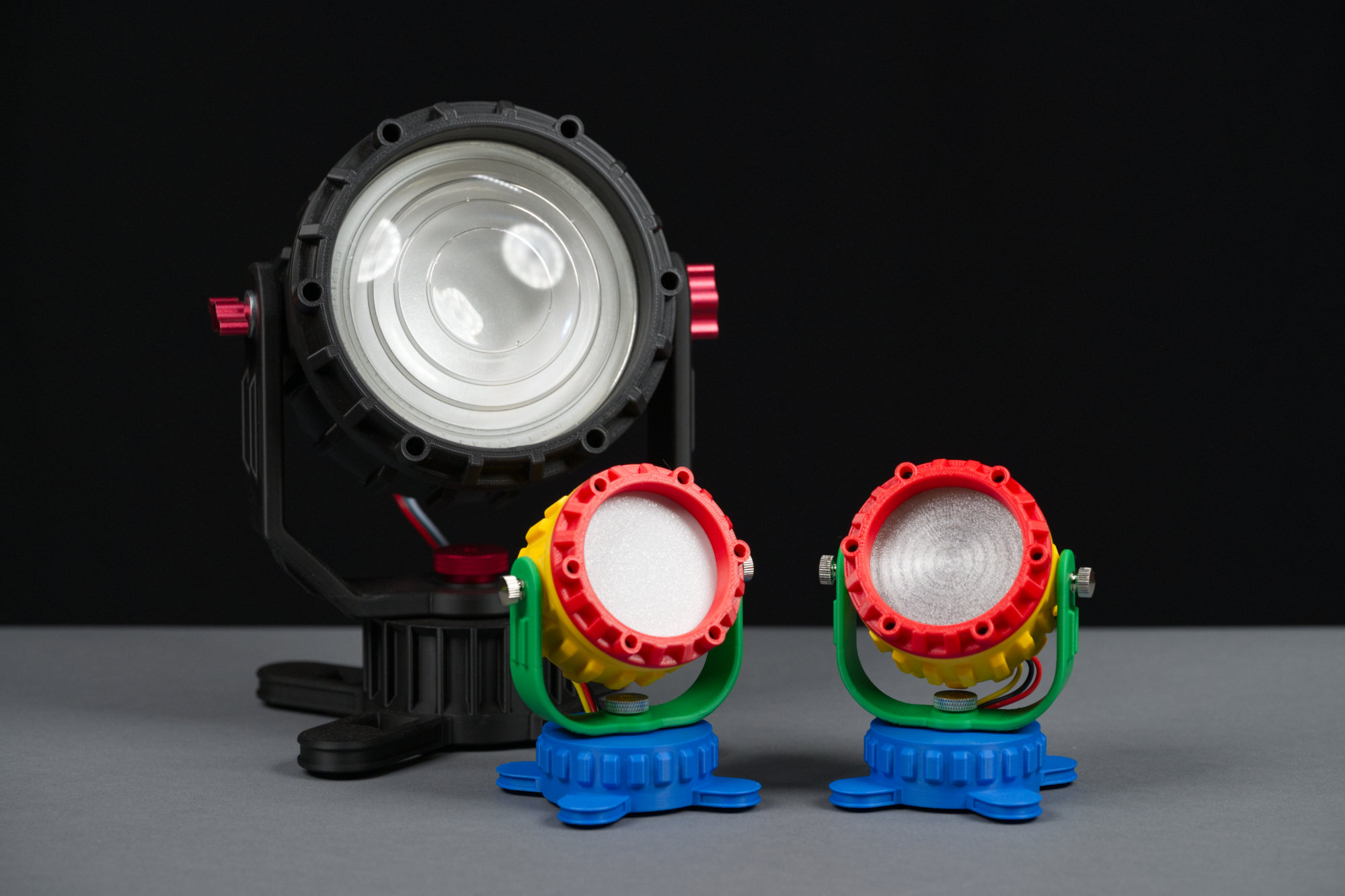
On the left is the light designed for direct viewing. It has a white translucent lens that diffuses the colors from the LEDs. On the right, is a light designed for washing small surfaces with different colors of light. It has an almost clear lens with a faux Fresnel lens pattern on it.
The standard lens, shown on the fixture on the left in the photo above, diffuses the light and is ideal for directly viewing the light from the LEDs. If you’d like to use the fixture for illumination like splashing a color on a wall, a translucent lens, as shown on the fixture on the right, will allow for more light to pass. The ready-to-print files for the translucent lens can be downloaded from the links in the table below. They consist of a spacer ring printed out of black PLA and a translucent lens printed out of clear translucent PETG.
| Part | Description | Download File | Filament | Print Time |
|---|---|---|---|---|
 |
Translucent Lens | clear_lens.3mf | Clear Translucent PETG | 17m |
 |
Spacer for Translucent Lens | clear_lens_spacer.3mf | Black | 9m |
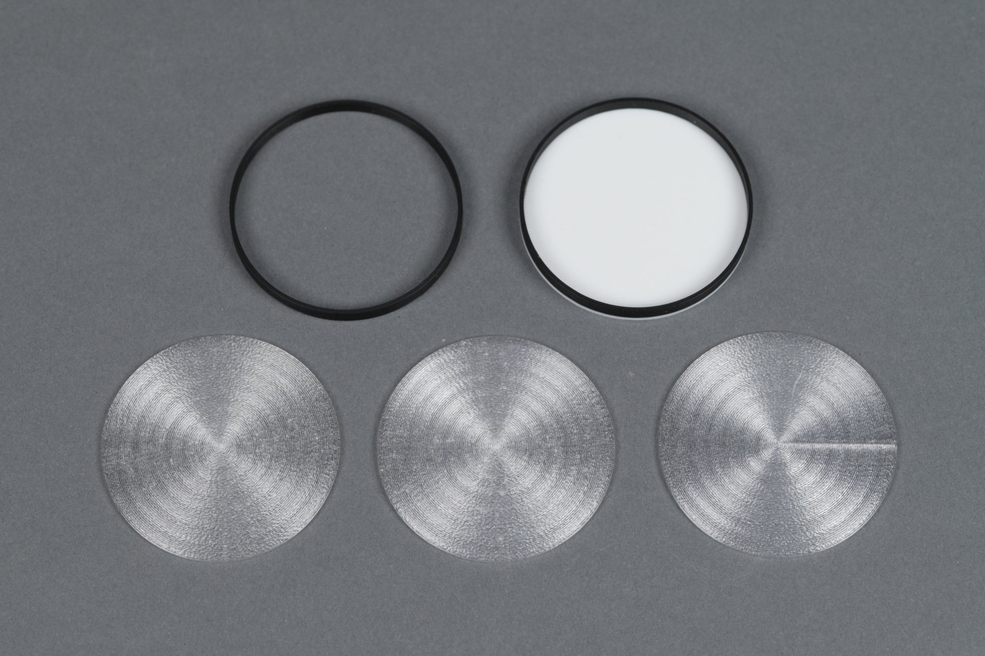
clockwise from upper left: a PLA ring to hold the clear PETG lenses in place, the standard two-color diffuser, a clear PETG lens printed with concentric infill and fixed seam position, a clear PETG lens.printed with Archimedes spiral infill, and a clear PETG lens with concentric infill and random seam positions.
The spacer ring uses the stock 0.2 mm slice print settings. The lens, however, is printed with 100% concentric ring infill and random seam alignment. This results in a lens with a circular pattern inside it and no large visible seam across it. The Archimedes infill pattern results in a spiral pattern inside it and is also aesthetically pleasing. Using anything other than a random seam alignment will likely result in a visible seam across the lens. The lens is 7 layers thick but could be printed thinner if desired which would allow even more light to pass.
Modifying the Design
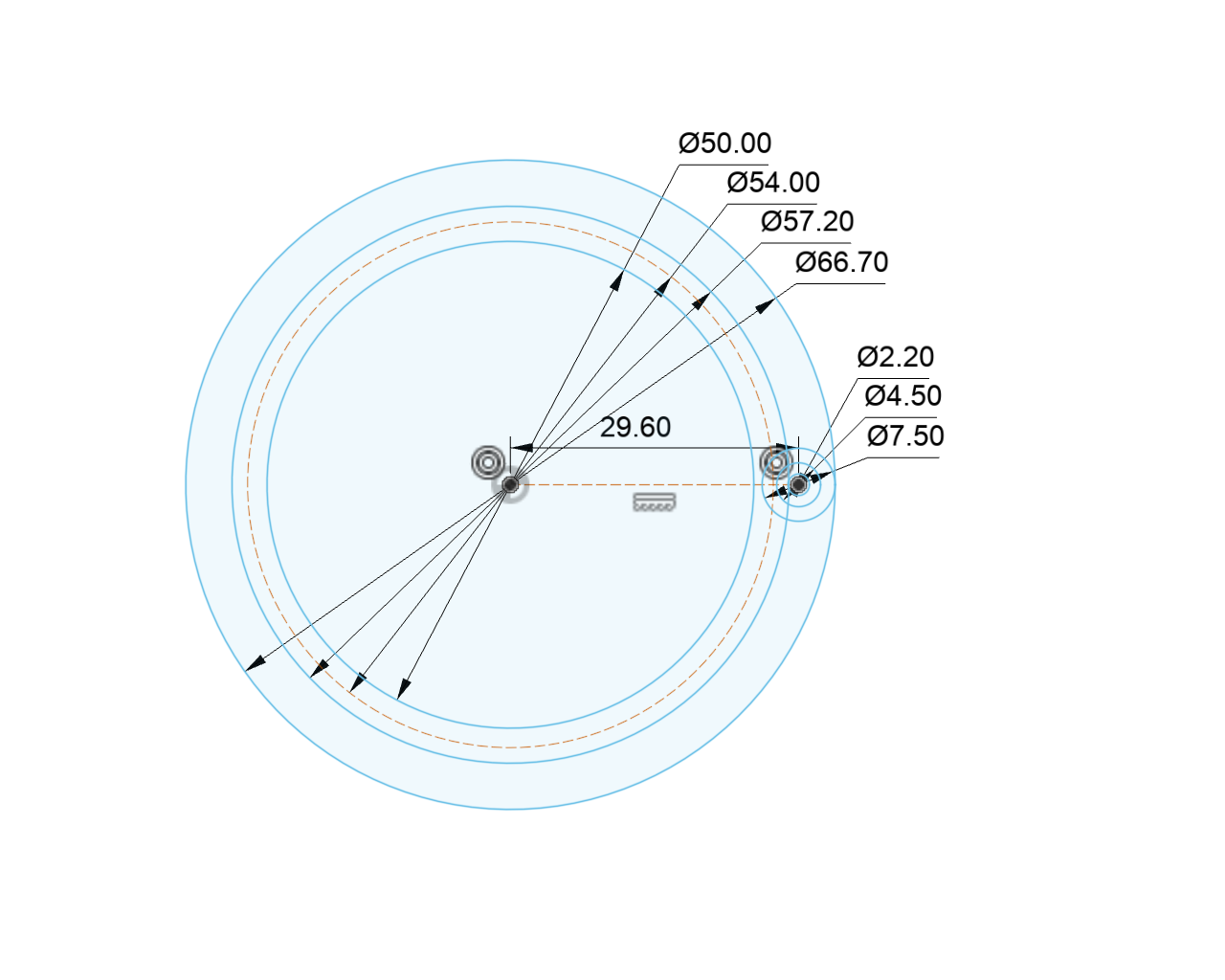
Lens retaining ring dimensions.
The design parameterization is focused on getting the lens retaining ring and main body housing dimensions correct. From there, the design history can be used to adjust the number of screws, the number and size of heat sink fins, and other design features.
The image above shows the main retaining ring dimensions and their values as included in the design file archive (linked below). Everything starts with the diameter of the lens opening (50 mm), the diameter of the lens (54 mm), and the size of the screws (M2 or 2 mm) and the diameter of the heads of the screws (a bit less than 4.5 mm). From those dimensions, the rest of the dimensions are calculated.
| lens diameter | 54 |
| lens opening diameter | 50 |
| screw hole diameter | 2 |
| screw fit clearance | 0.2 |
| screw head opening diameter | 4.5 |
| screw lens clearance | 1.5 |
| screw shroud thickness | 1.5 |
| screw ring diameter | 59.2 |
| screw shroud diameter | 7.5 |
| outside diameter | 66.7 |
| upper ring diameter | 57.2 |
To assist in setting the parameters, a spreadsheet is linked below. The values from the spreadsheet are shown in the table above. Everything below and including screw ring diameter is computed from the values above screw ring diameter.
Download the spreadsheet, adjust these values, then copy and paste the spreadsheet values into the design parameters and you should be able to adjust the dimensions of the lens ring and main housing to fit any sized lens or retaining ring screws.
This mostly works but you’ll likely still need to use the sketches and design history to adjust the location of the M4 nut cavities and cosmetic features like the heatsink fins. If you get lots of errors in the design history, backing up the design history to the error then editing the feature, even if it’s just clicking edit and immediately clicking ok, can sometimes fix the errors
The spreadsheet:
Excel Workbook for Calculating Housing Sizes
The complete Autodesk Fusion archive:
Related: