
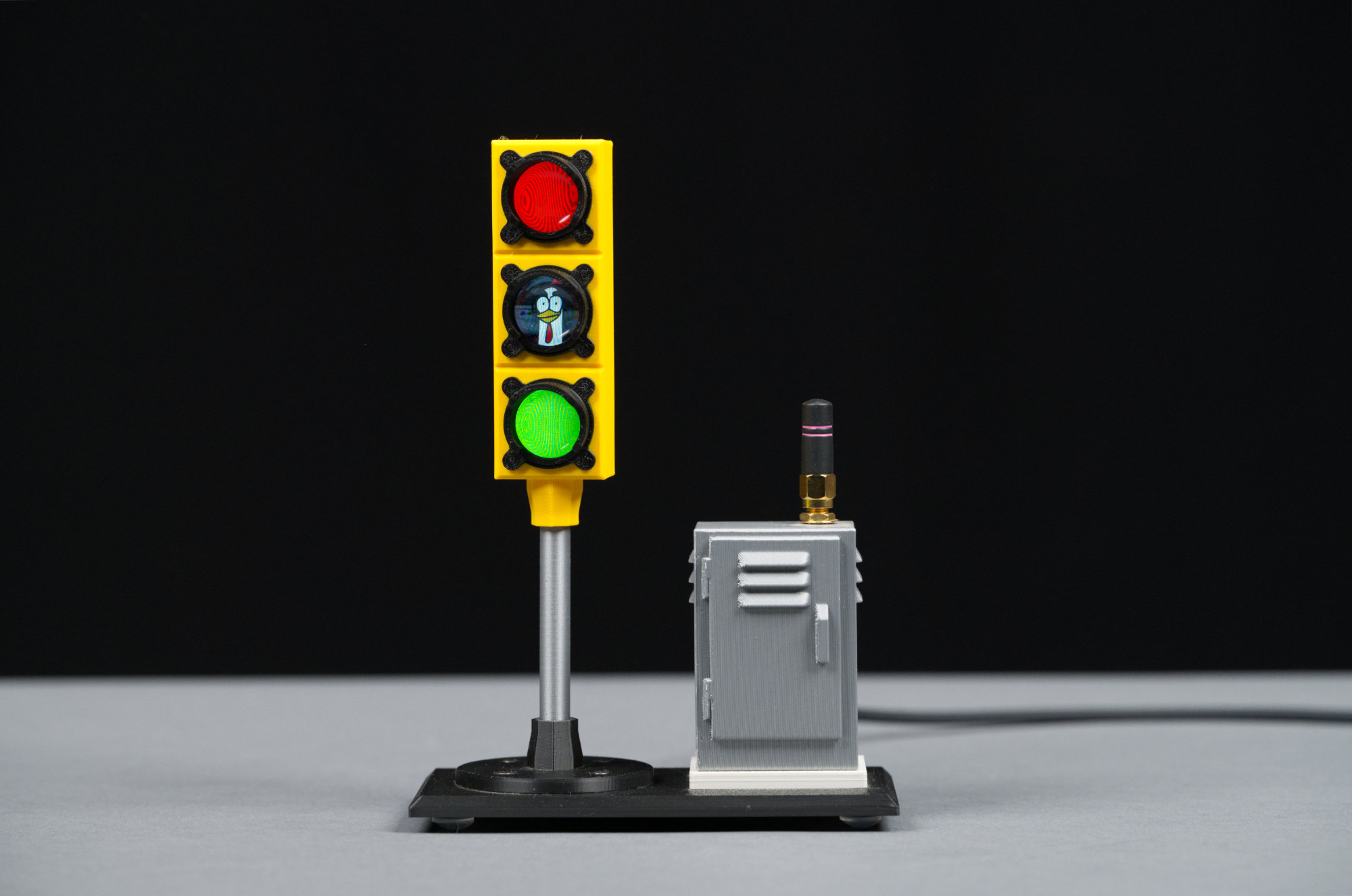
The completed LCD traffic signal including body, mast, controller cabinet with Wi-Fi antenna, concrete pedestal for the controller, and platform.
In this project, I build a miniature 3D-printed traffic signal and matching Wi-Fi-enabled controller cabinet. The big twist is that each light on the signal is really a small round LCD permitting traditional traffic signals like bicycles, globes, and arrows as well as random images to be displayed—without disassembling or taking apart the signal.
Inspiration
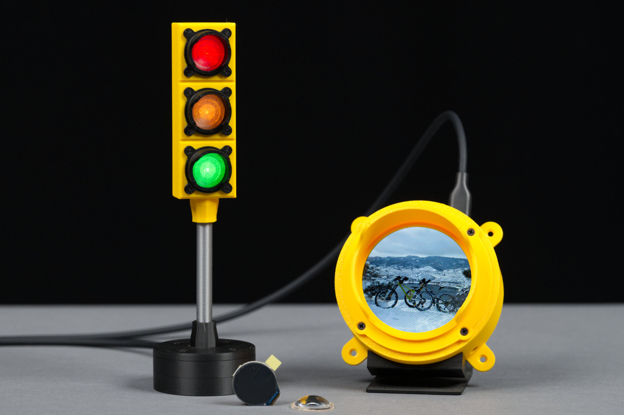
On the left, a 3D-printed USB-controlled neopixel traffic light. The electronics are in the base. On the right is a circular LCD also in a 3D-printed traffic light housing. Front center is a Waveshare 0.71″ LCD and its acrylic cabochon lens.
Two of the first projects I built with my 3D printer are shown in the photo above. On the left is a traditional traffic signal built with three W2812b Neopixel RGB LEDs. Each aspect of the signal face can be set to an arbitrary color from a terminal window. They use a PIC16F1454 emulating a USB communications device class device for a controller.
On the right is a 2.1″ round LCD driven by an Adafruit Qualia ESP32-S3 board running CircuitPython. The housing is styled after a vintage Crouse-Hinds Type RM traffic signal unit from the early 1900s. It’s neat being able to display arbitrary images on the round LCD.
In the foreground is a small 0.71″ Waveshare LCD module. After ordering a bunch of these small displays, I wondered if I could build a three aspect traffic signal like the one on the left in the photo above except using an LCD display instead of just a simple color changing LED.
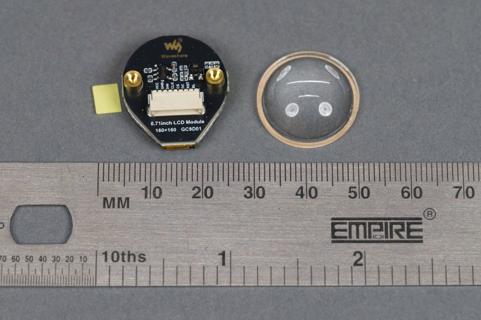
The Waveshare 0.71″ round LCD is indeed small at only 18 mm in diameter. Each LCD includes a small round lens that affixes to the display using pressure sensitive adhesive.
The Waveshare displays are small, measure only 18 mm in diameter, and are mounted on a board that measures roughly 20 x 22 mm. The 16-bit color displays are 160 x 160 pixels and use a GC9D01 controller with a SPI interface. They connect to a microcontroller using an 8-pin JST SH 1 mm pitch connector. Each display includes a small acrylic cabochon lens.
About the Design
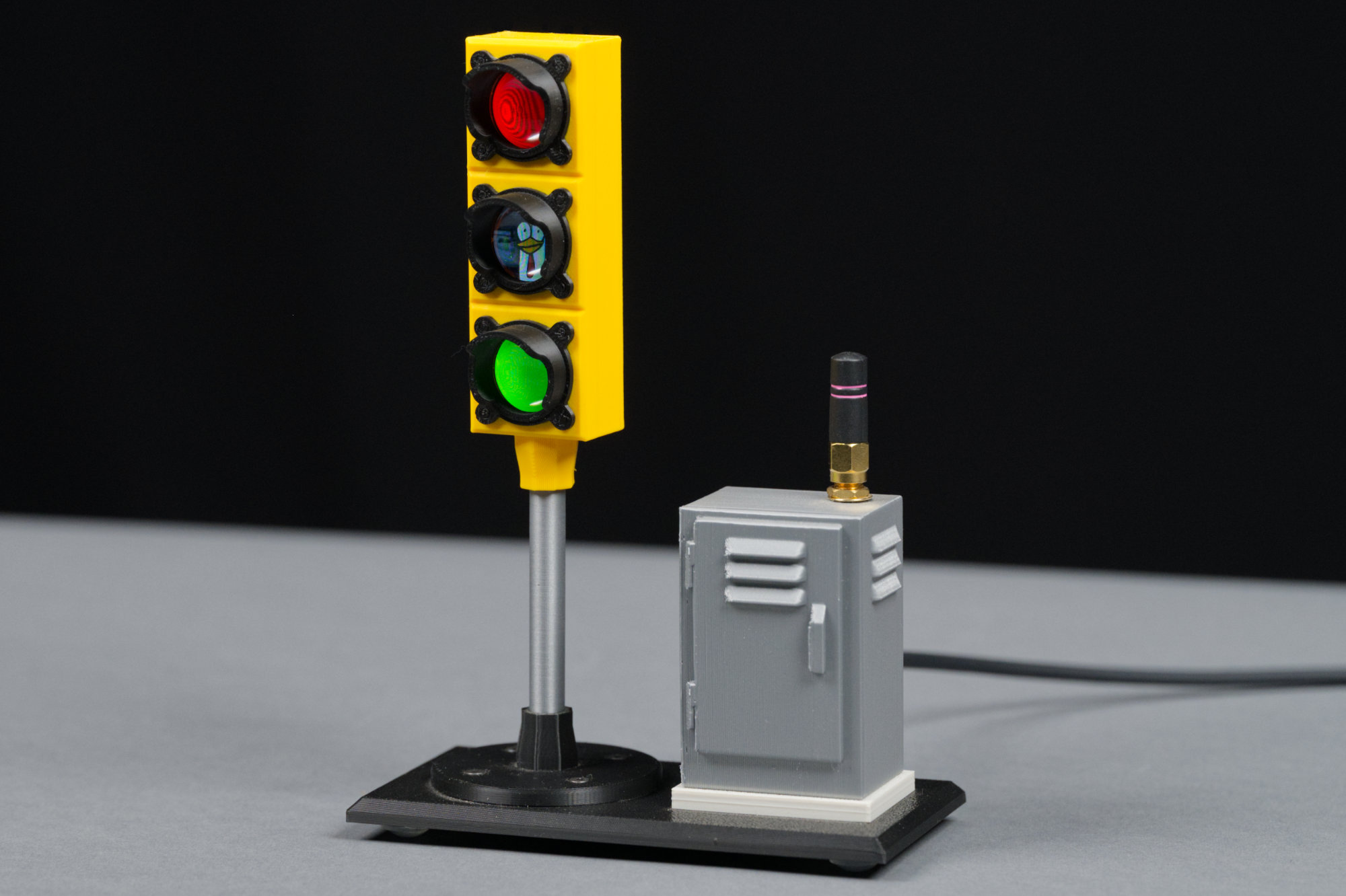
Angled view of the completed LCD traffic signal including body, mast, controller cabinet with Wi-Fi antenna, concrete pedestal for the controller, and platform.
After a few prototypes and wondering what to do about all the wires and required microcontroller, I settled on the final design shown in the photo above. The main signal body is exactly the same size as the Neopixel RGB LED controller but houses three full-color 160 x 160 pixel LCD modules! The electronics have been moved from the round base to a controller cabinet that looks just like the street-side cabinet at a real intersection. The entire project is just under 180 mm tall.
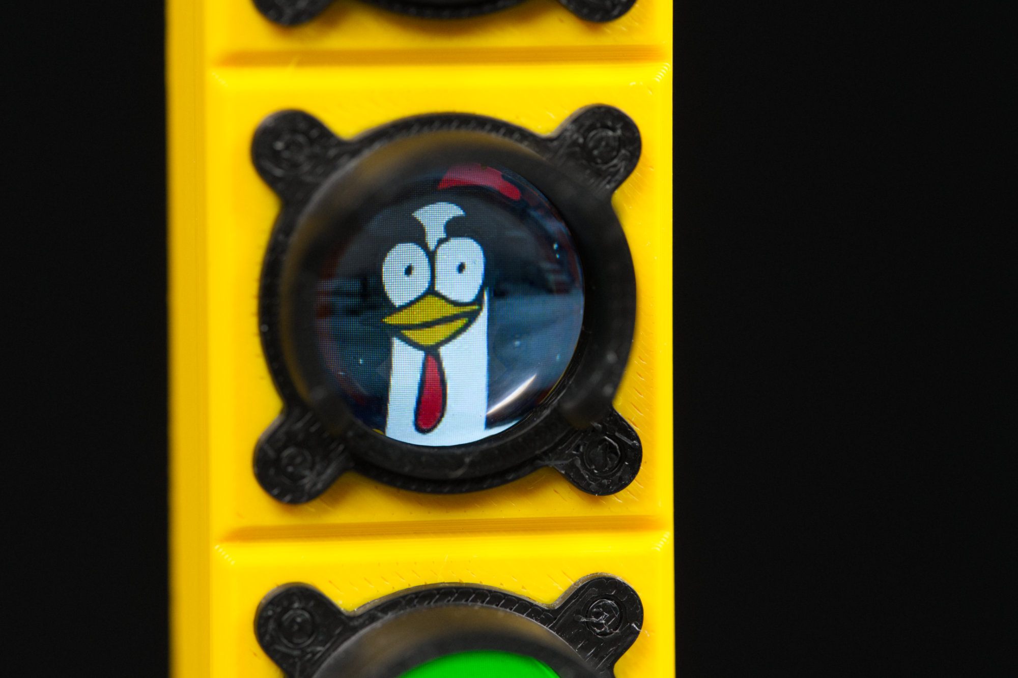
Each signal aspect is a 160 x 160 LCD module capable of displaying full color images.
Each signal aspect is a little miniature display. This one is displaying the profile picture I use on many social media sites (and at my day job).
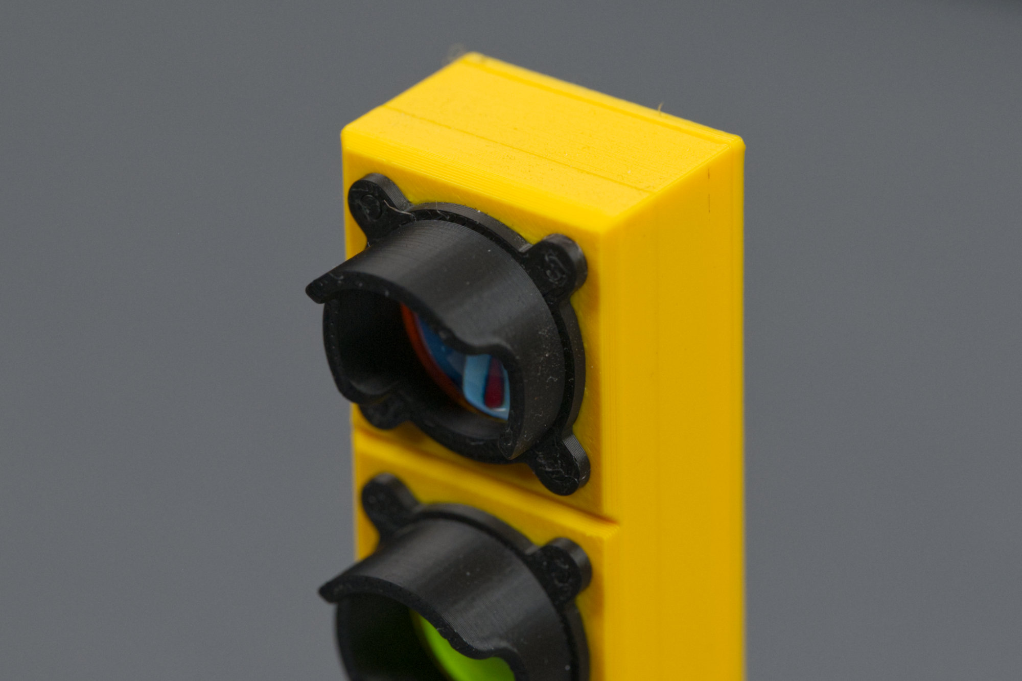
Each signal aspect includes a black hood.
Each aspect has a black sun hood to shield the display from ambient light like a real traffic signal. The housing and the hoods are printed as a single piece using Bambu Lab’s AMS but they could be printed separately and glued together if necessary.
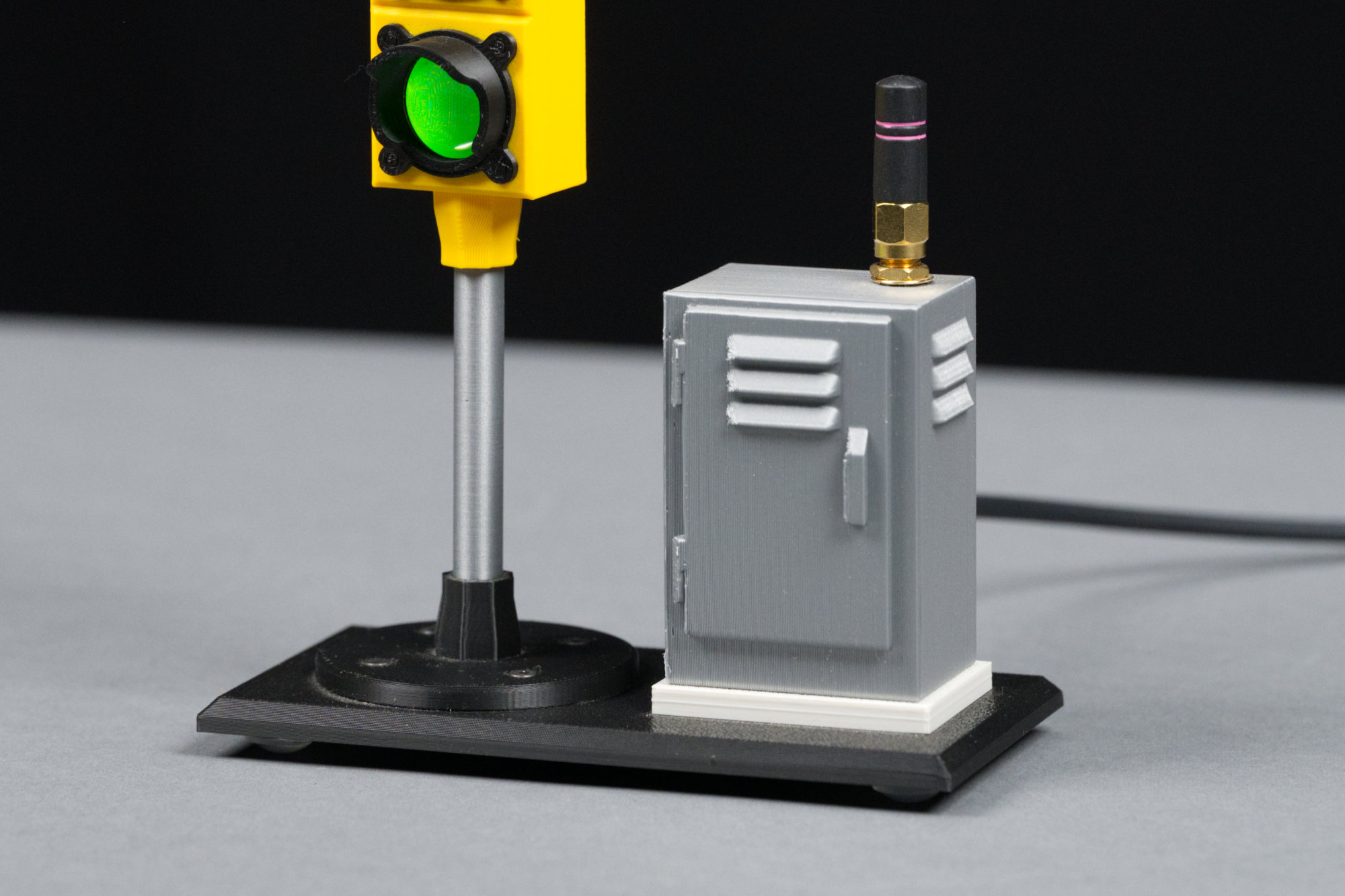
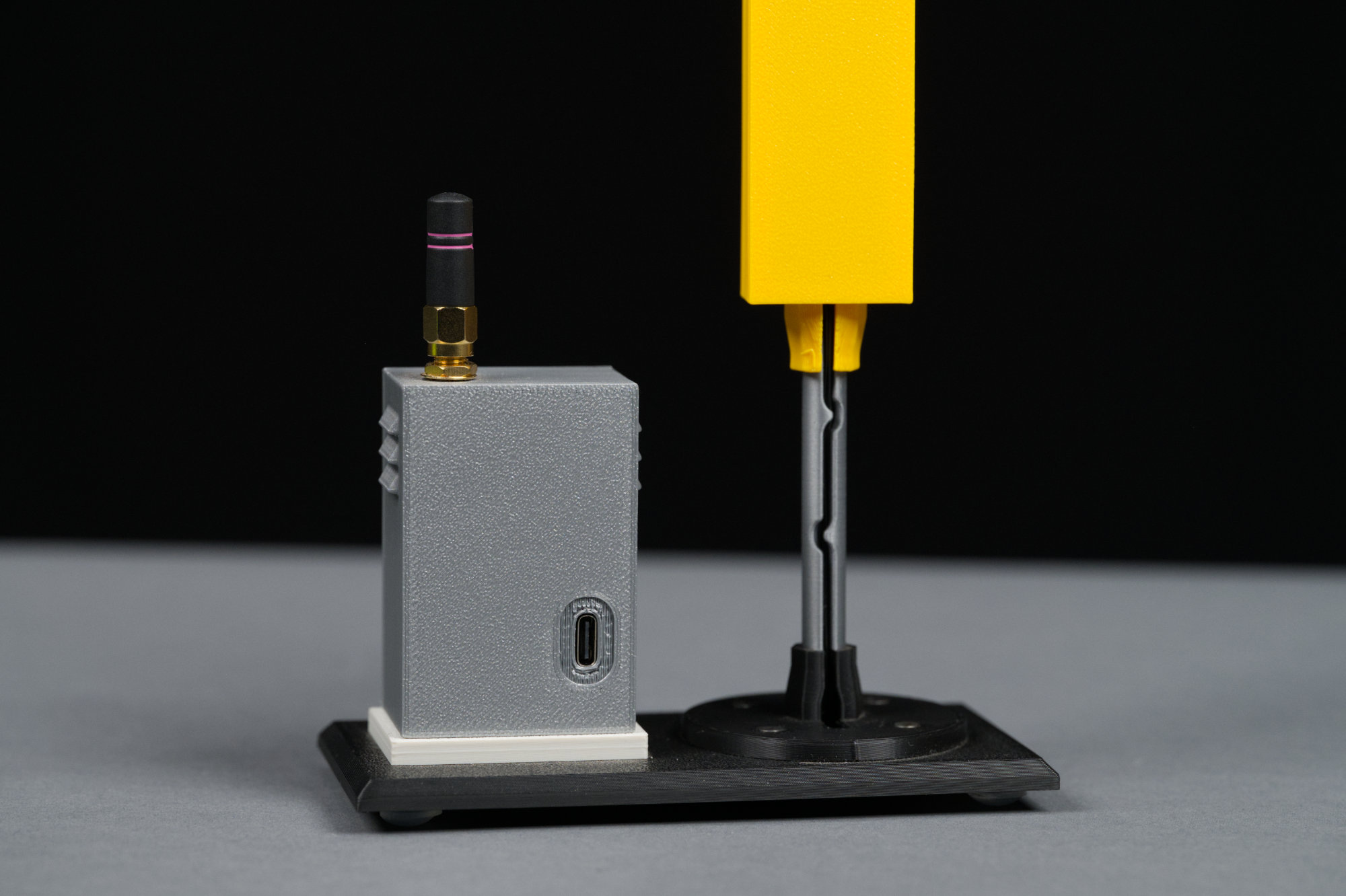
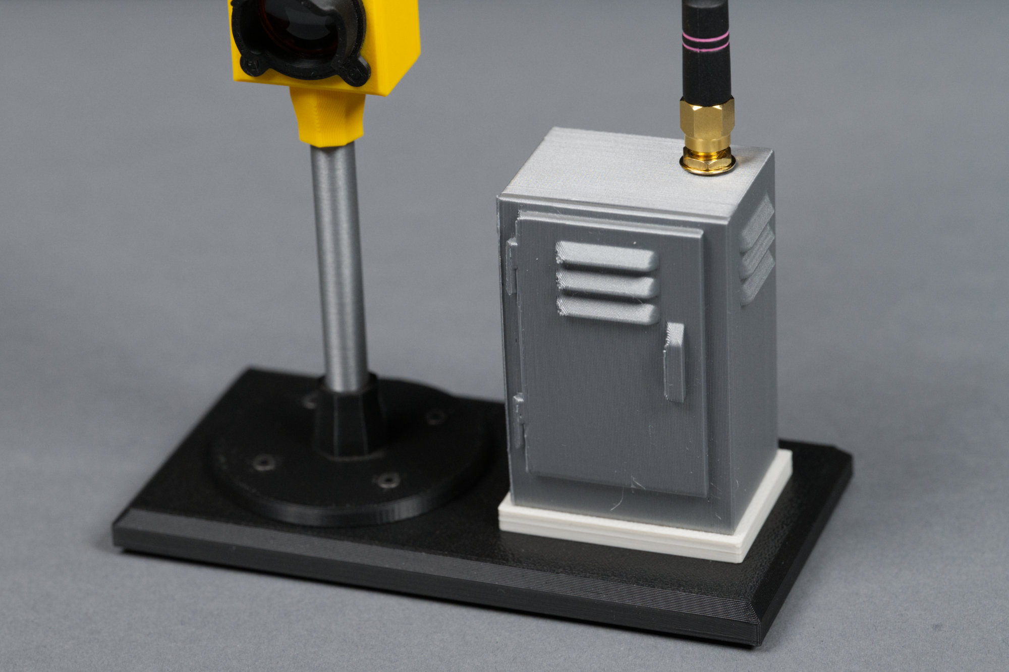
A close up of the signal mast and controller cabinet.
To the right of the signal is a controller cabinet. The controller cabinet rests on a concrete pedestal. On top of the controller cabinet is my favorite 2.4 GHz Wi-Fi antenna that doesn’t require a separate ground plane. If you build lots of these, you can use Wi-Fi and MQTT to synchronize their operation!
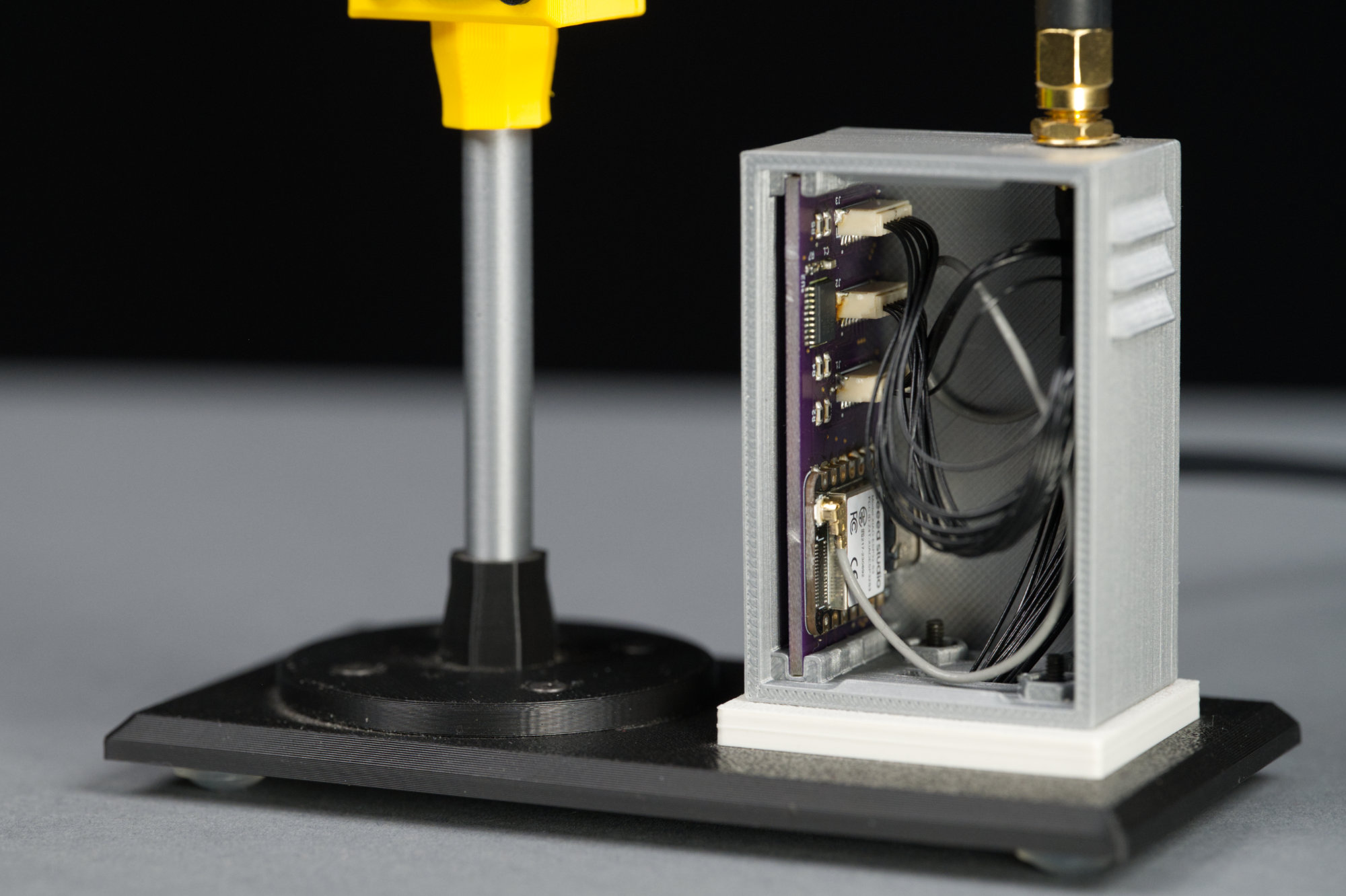
The controller cabinet houses the electronics that control the LCDs.
Inside the controller cabinet are the electronics that control the traffic signal. Conceivably the electronics are small enough to fit in a round base under the signal but the cabinet is cute and more like a real traffic signal.
On the back of the controller cabinet is USB C port for powering and programming the project. On the back of the signal mast is a slot for routing the pre-terminated cable assemblies from the LCD to the controller.
On the back of the controller cabinet is a USB 2.0 Type C connector for powering and programming the traffic signal. I used pre-terminated JST SH cable assemblies to connect the displays to the controller. These assemblies required me to add a slot down the back of the mast and rectangular holes in the platform, stand, and cabinet to route the cables and connectors without disassembling the cables.
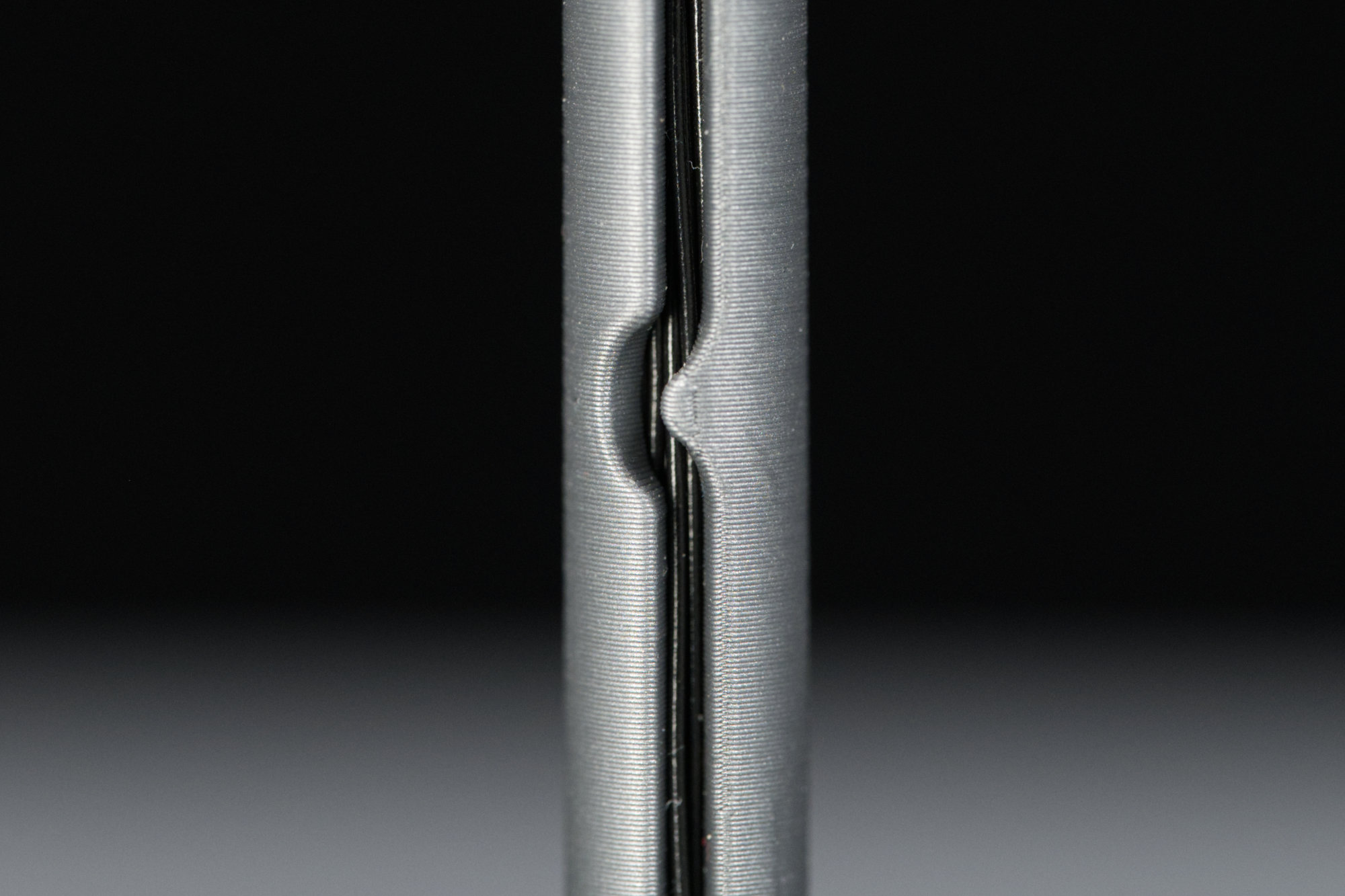
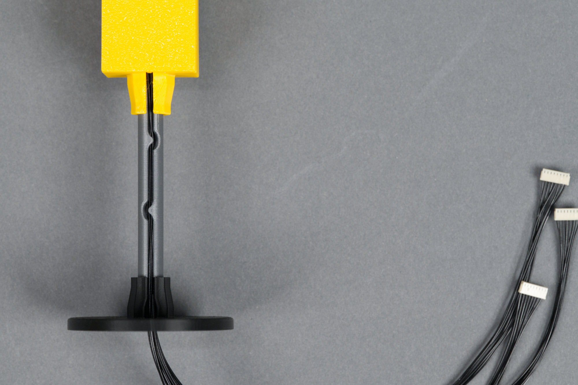
There’s 24 separate wires inside the signal mast!
Inside the slot are 24 wires—eight for each display! It’s amazing that they fit but they do! The wires are held in place using the two hooks sculpted into the mast.
Bill of Materials
This project requires some electronics, some mechanical hardware, some 3D printed plastic pieces, and a custom controller printed circuit board. The parts required are listed in this section. Building the controller and printing the plastic pieces is detailed in following sections.
Electronics
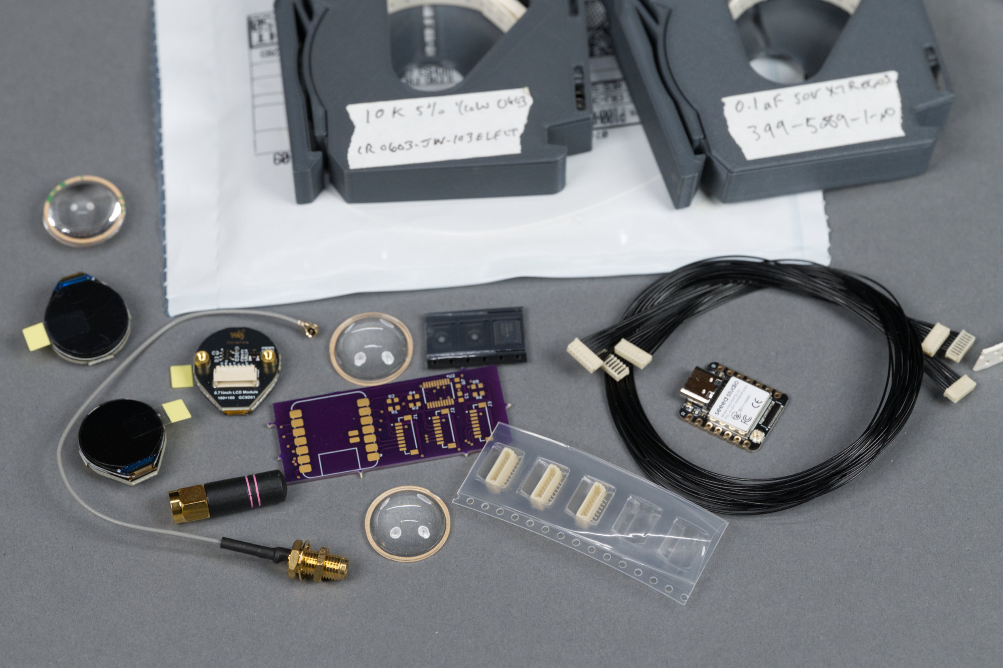
It’s a bit of a mess but it’s mostly cabling, connectors, and passives.
The electronics for this project consists of three small LCD displays, cables to connect the displays to a controller card, the parts for the controller card, a Wi-Fi antenna, and a cable to connect the Wi-Fi antenna to the controller card. A lower cost antenna and antenna cable can be substituted for the specified parts or the patch antenna supplied with the XIAO board can be stuck to the controller cabinet’s right interior wall.
| Quantity | Description | Manufacturer | Part Number |
|---|---|---|---|
| 3 | 0.71″ round 160×160 LCD | Waveshare | 29380 |
| 3 | JST SR 1.00mm 8 position 12″ cable assembly | JST | A08SR08SR30K305A |
| 3 | JST SR 1.00mm 8 position SMT vertical header | JST | BM08B-SRSS-TB(LF)(SN) |
| 1 | XIAO ESP32S3 module, no headers | Seeed Studio | 113991114 |
| 1 | Octal non-inverting level translator / buffer IC | Texas Instruments | SN74LVC245APWR |
| 1 | 10k 5% 0605 resistor | Generic | — |
| 6 | 100 5% 0605 resistor | Generic | — |
| 1 | 0.1 uF 0605 capacitor | Generic | — |
| 1 | Miniature 2.4GHz RP-SMA antenna | TE Connectivity Linx | ANT-2.4-CW-RH-RPS |
| 1 | 100mm U.FL to RP-SMA coax cable assembly | Amphenol RF | 336314-13-0100 |
Hardware
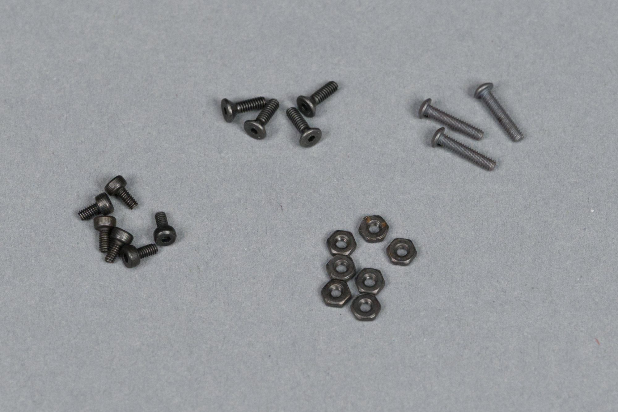
Nuts and bolts.
Hardware for this project consists of screws to mount the displays to their mounting frame and to attach the stand and controller cabinet to the base platform.
| Quantity | Size | Purpose |
|---|---|---|
| 6 | M2 x 4mm pan head hex screws | Mount displays to display mounting plate |
| 3 | 2-56 x 7/16″ pan head hex screws | Mount controller cabinet to base platform |
| 4 | 2-56 x 5/16″ black oxide flat head hex screws | Mount stand to base platform |
| 7 | 2-56 hex nuts | — |
| 4 | 0.315″ diameter rubber feet, e.g. DigiKey #SJ5076 | — |
Filament
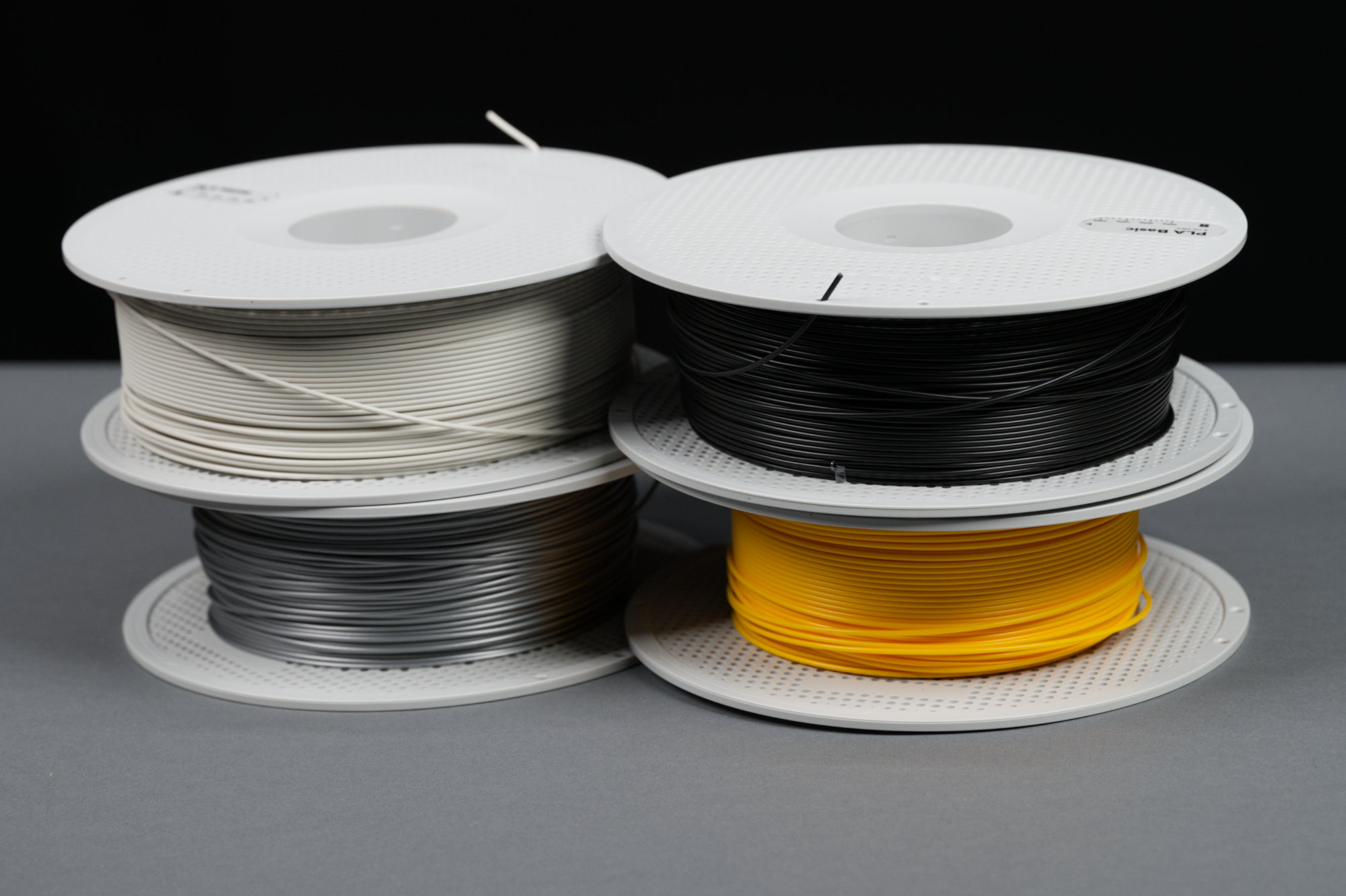
The Bambu Lab PLA filaments used for the project.
I used Bambu’s PLA filament for this project. I’ve had success using filament from Polyterra and Polar Filament as well. The links below take you to the specific Bambu filaments I used for this project:
- Sunflower Yellow Basic PLA
- Black Basic PLA
- Bone White Matte PLA
- Silver Basic PLA (or Iron Gray Metallic PLA)
Building the Controller
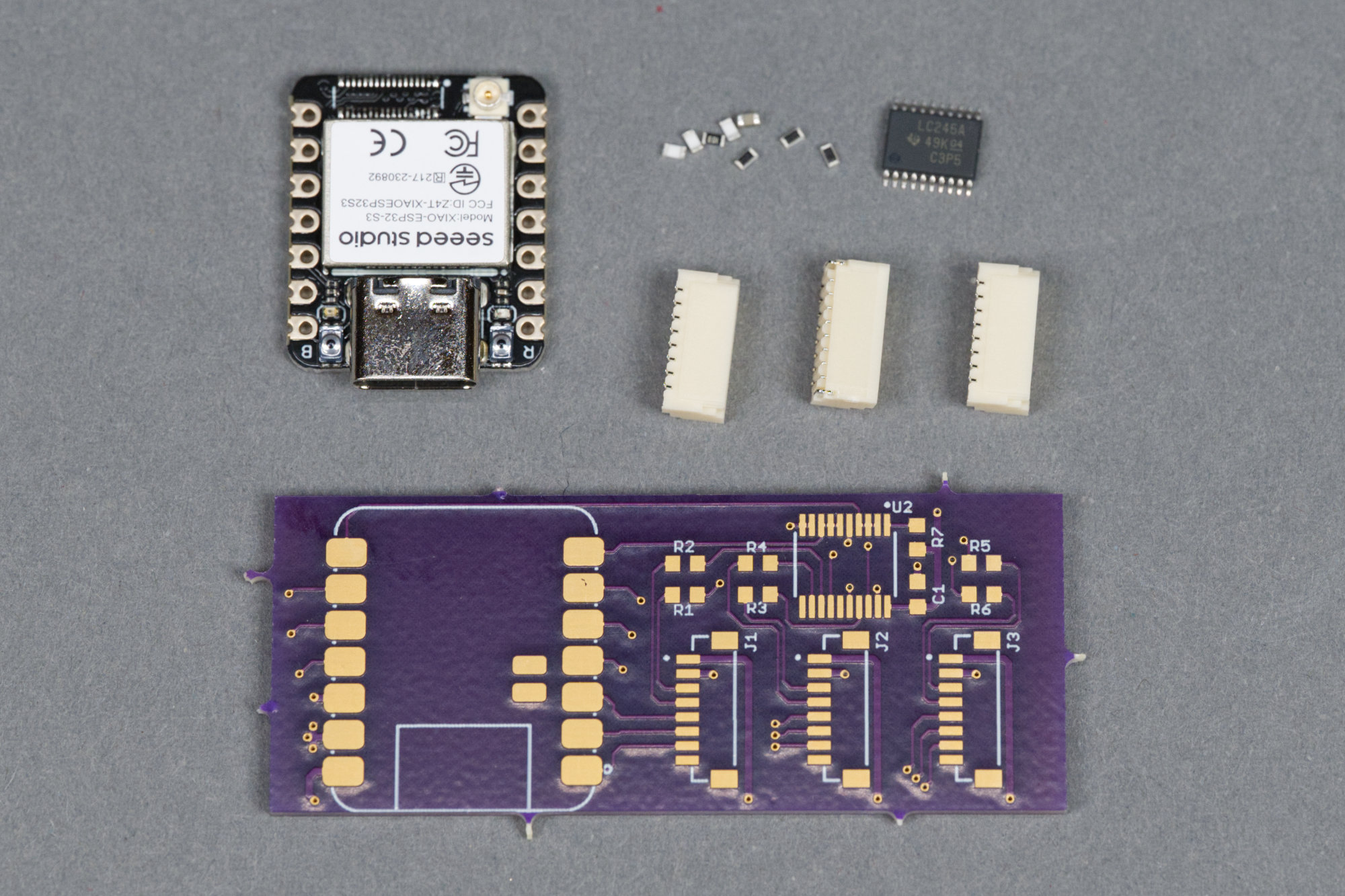
The XIAO ESP32-S3 module that forms the heart of the signal controller plus the circuit board, connectors, buffer IC, and passives.
The photo above shows the parts required to build the controller for the signal. They’re all surface mount.
Schematic
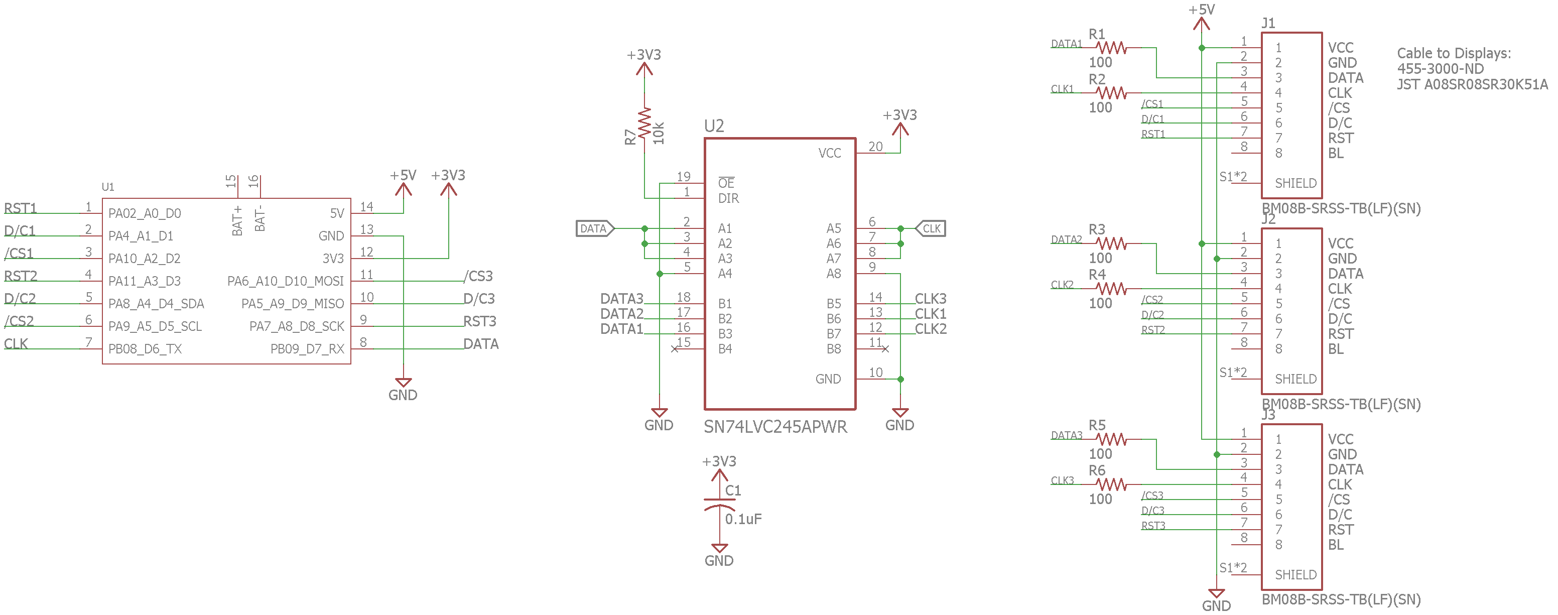
Completed schematic for the controller board.
The schematic for the controller is shown above. At the heart of the controller is a Seeed Studio XIAO ESP32-S3 module. It can run CircuitPython which makes displaying images on the displays much easier than using the Arduino development environment.
The low-speed, per-display signals like control/data selects and chip selects run directly from the XIAO module to the displays. The common high-speed clock and data signals are buffered, duplicated, and ran through some 100 Ω resistors to lessen ringing and emissions and ran to the displays. Then it’s just 1 mm pitch JST SH headers.
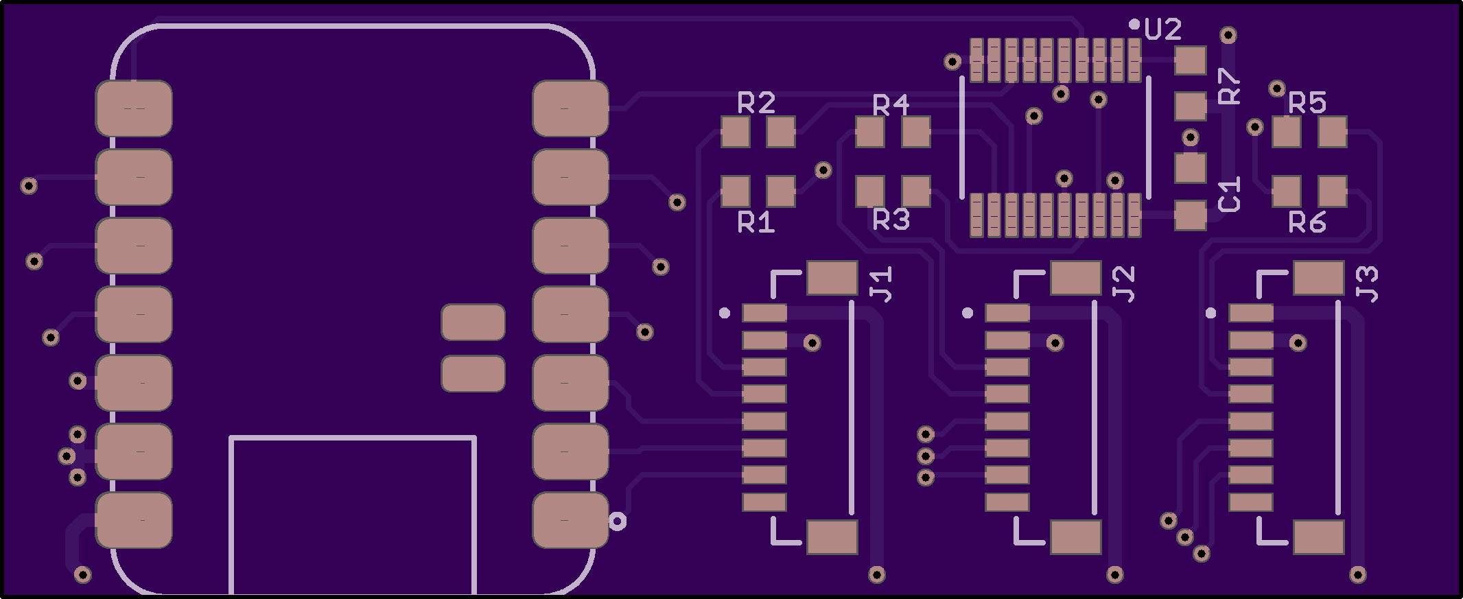
Layout
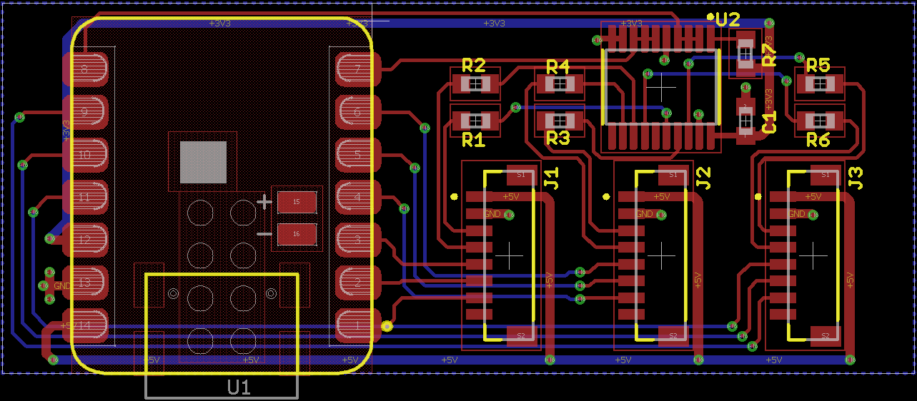
Completed layout for the controller board.
The board layout is nothing spectacular. There is, however, a large keepout on the top layer under the XIAO module where no traces or vias can be run to keep from shorting them to the XIAO module.
OSH Park preview of the board top.
I fabbed the boards at OSH Park. The preview for the board top is shown above.
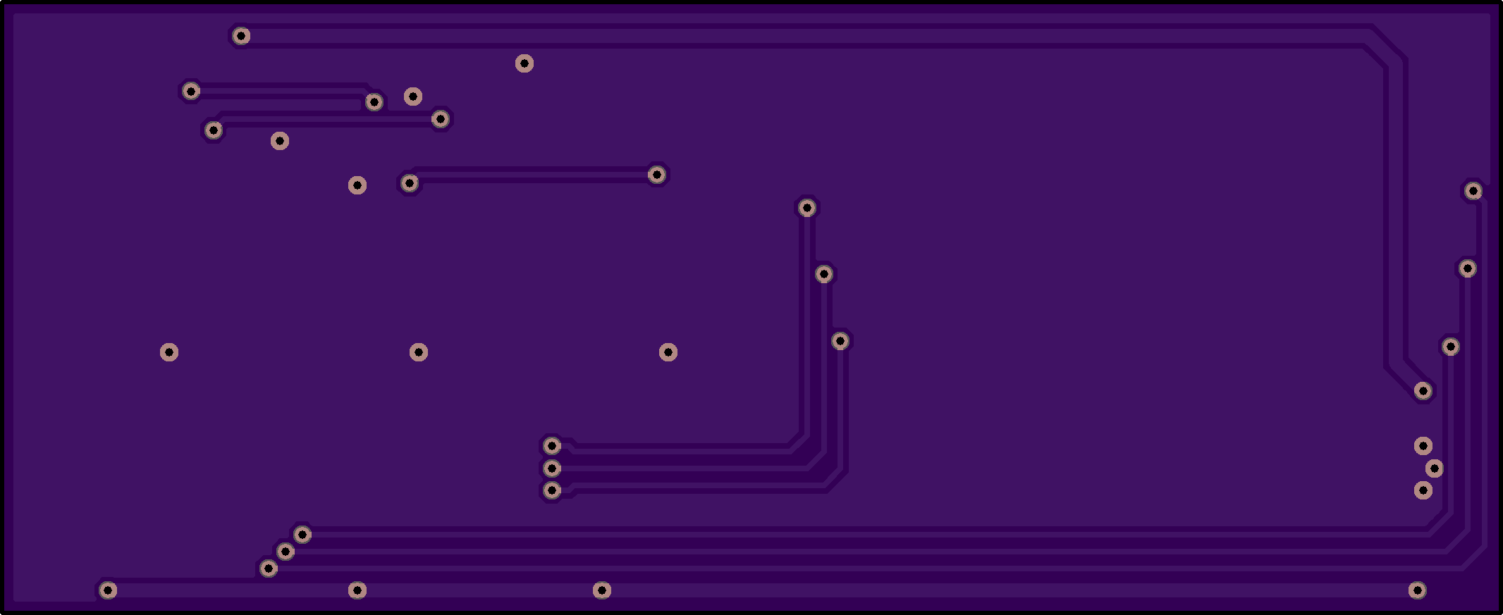
OSH Park preview of the board bottom.
And the preview for the board bottom is shown above.
Boards
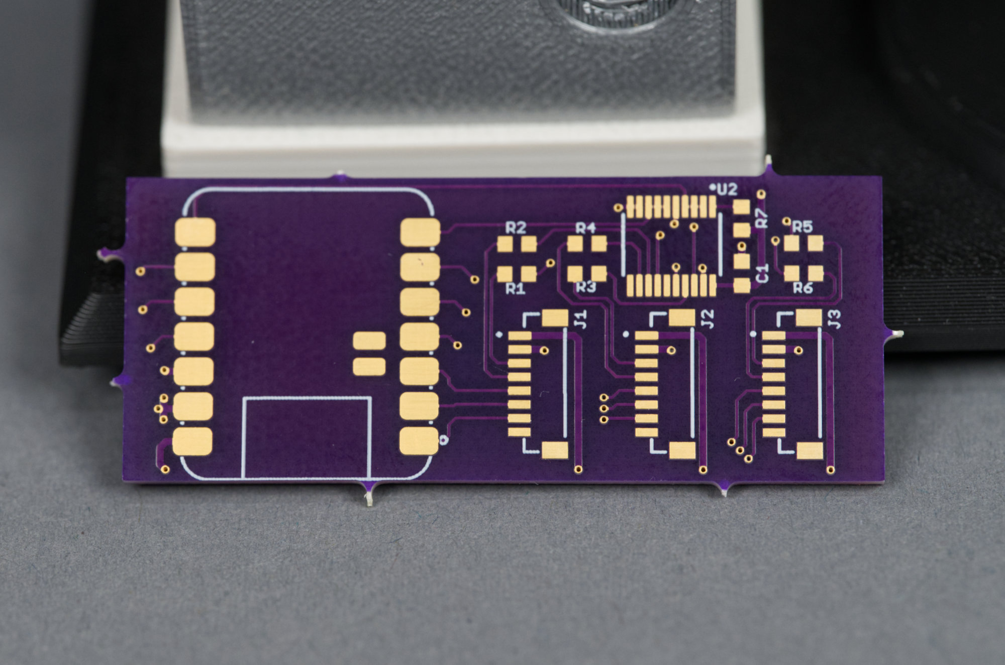
Board fabbed at OSH Park complete with trademark purple color and mouse bites.
The fabbed board is shown above. The mouse bites must be removed for the board to fit in the controller cabinet. I used a rotary tool, safety glasses, and an N95 respirator to grind off the mouse bites.
Assembly
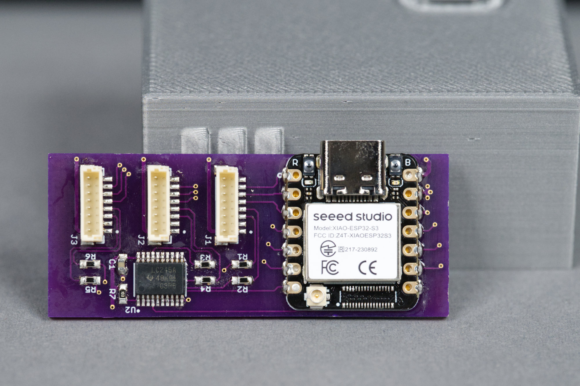
The assembled controller board. The mouse bites have been ground off to allow the board to fit in the controller cabinet.
The assembled control board is shown in the photo above. After grinding off the mouse bites, I started assembly by tacking down two opposite corners of the XIAO module then test fitting the board and USB C connector in the controller cabinet. Since everything was aligned and fit, I finished soldering the module then moved on to the rest of the components.
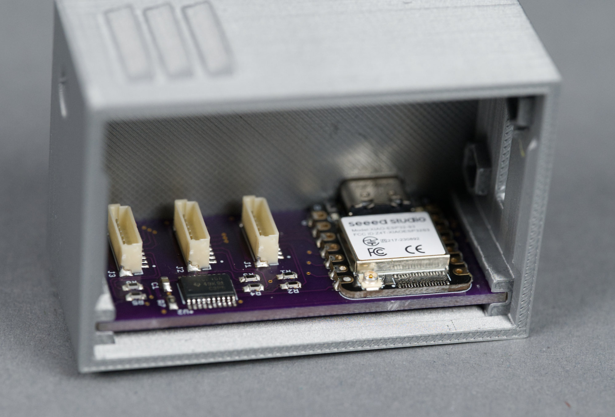
The completed controller board seated in the controller cabinet.
The completed controller seats comfortably in its slots inside the controller cabinet in the photo above. A USB C cable should fully plug into the XIAO module from the rear of the cabinet.
Installing Software on Controller
The controller runs CircuitPython. The biggest catch is that the default build for the XIAO ESP32S3 module supports a maximum of one display. This necessitates changing a constant in the CircuitPython sources and building them for the module.
Fortunately, Tod Kurt over at todbot.com has complete instructions on how to do this. There’s also an Adafruit Learn Guide to Building CircuitPython. I’ve replicated and updated the instructions below.
Build CircuitPython with Support for Three Displays
First, make a Python venv, check out the code, fetch the submodules, and install the required Python dependencies:
python3 -m venv build
source build/bin/activate
git clone https://github.com/adafruit/circuitpython circuitpython-glen
cd circuitpython-glen
make fetch-all-submodules
git checkout main
pip3 install --upgrade -r requirements-dev.txt
pip3 install --upgrade -r requirements-doc.txt
make -C mpy-cross
Now install the Espressif ESP-IDF and build CircuitPython for the Seeed Studio XIAO ESP32-S3 Sense module (which is close enough to the non-sense version of the module):
cd ports/espressif
make fetch-port-submodules
deactivate
./esp-idf/install.sh
. ./esp-idf/export.sh
pip3 install minify.html
pip3 install jsmin
sudo apt install cmake (if not already installed)
sudo apt install ninja-build (if not already installed)
make -j10 BOARD=seeed_xiao_esp32_s3_sense
ls -l build-seeed_xiao_esp32_s3_sense
There should be a firmware.uf2 file in the directory:
-rw-r--r-- 1 glen glen 3672576 Jan 8 21:06 firmware.uf2Now increase the number of supported displays to 3 by editing (or adding if not present) the following line and setting the number of displays to 3 in boards/seeed_xiao_esp32_s3_sense/mpconfigboard.h:
#define CIRCUITPY_DISPLAY_LIMIT (3) Rebuild the firmware.uf2 file with the changed display count:
make -j10 BOARD=seeed_xiao_esp32_s3_sense
ls -l build-seeed_xiao_esp32_s3_sense
And the result:
-rw-r--r-- 1 glen glen 3673600 Jan 8 21:11 firmware.uf2If you have trouble building the firmware.uf2 file, you can use this one. These steps worked for building CircuitPython 10.0.3.
Install the UF2 Bootloader on the XIAO Module
The next step is to install the UF2 bootloader on the XIAO module. This can be done from this webpage using a Chromium-based browser such as Microsoft Edge or Google Chrome. Click “Open Installer” then select “Install Bootloader Only.” Follow the on-screen prompts. Do not skip the full erase. Reset or power cycle the board and the volume “XIAOS3BOOT” should mount on your PC.
Install the Modified CircuitPython Build on the XIAO Module
Drag the newly created firmware.uf2 file to the XIAOS3BOOT volume to install CircuitPython on the module. A few seconds after the file is finished copying, a new volume named “CIRCUITPY” should mount on your PC.
Install Example CircuitPython Code on the XIAO Module
Download this zip file and extract the files. Drag the extracted files, not the folder with the extracted files, into the CIRCUITPY drive. When prompted to replace the existing code.py, click replace. This code was tested against CircuitPython 10.0.3.
Test Displays and Wiring
Power down the controller board and connect the displays to the controller. Power up the controller board, and after about 10 seconds, the displays should display red, yellow, and green then start to pop the chicken from one display to the next. A bit of static on the displays after power up is normal.
Printing the Design
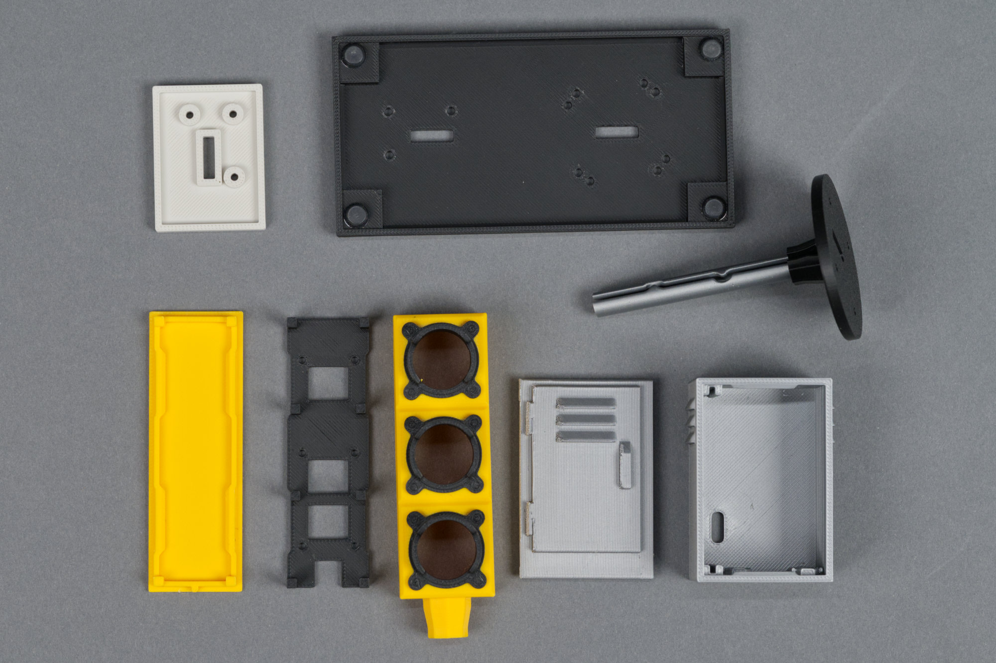
The finished 3D printed parts for this project.
I designed the 3D printed parts in Fusion then printed them on a Bambu Lab X1C. The .3mf files below should be ready to print and slice on Bambu and similar printers.
The signal housing requires supports and is printed using two colors of filaments. If you don’t have access to a multicolor printer, a manual filament change between the body and hood layers can be done or the entire piece printed out of just black or just yellow filament.
The signal mast is also printed using two colors of filament and a manual filament change is possible between the black and silver portions if needed. The cabinet door prints at a 45 degree angle and requires supports. It could also be printed flat on its back with supports.
| Part | Description | Download File | Filament | Print Time |
|---|---|---|---|---|
| Signal Hoods and Body | signal_hoods_and_body.3mf | Sunflower Yellow, Black | 1h50m | |
| LCD Mounting Plate | lcd_mounting_plate.3mf | Black | 28m | |
| Signal Body Rear Lid | signal_body_rear_lid.3mf | Sunflower Yellow | 24m | |
| Stand or Mast | stand.3mf | Black, Silver | 1h02m | |
| Signal Platform | platform.3mf | Black | 35m | |
| Concrete Pedestal | pedestal.3mf | Bone White | 20m | |
| Controller Cabinet | cabinet.3mf | Silver | 1h00m | |
| Cabinet Door | cabinet_door.3mf | Silver | 49m |
Putting Everything Together
1) Install lenses on LCDs.
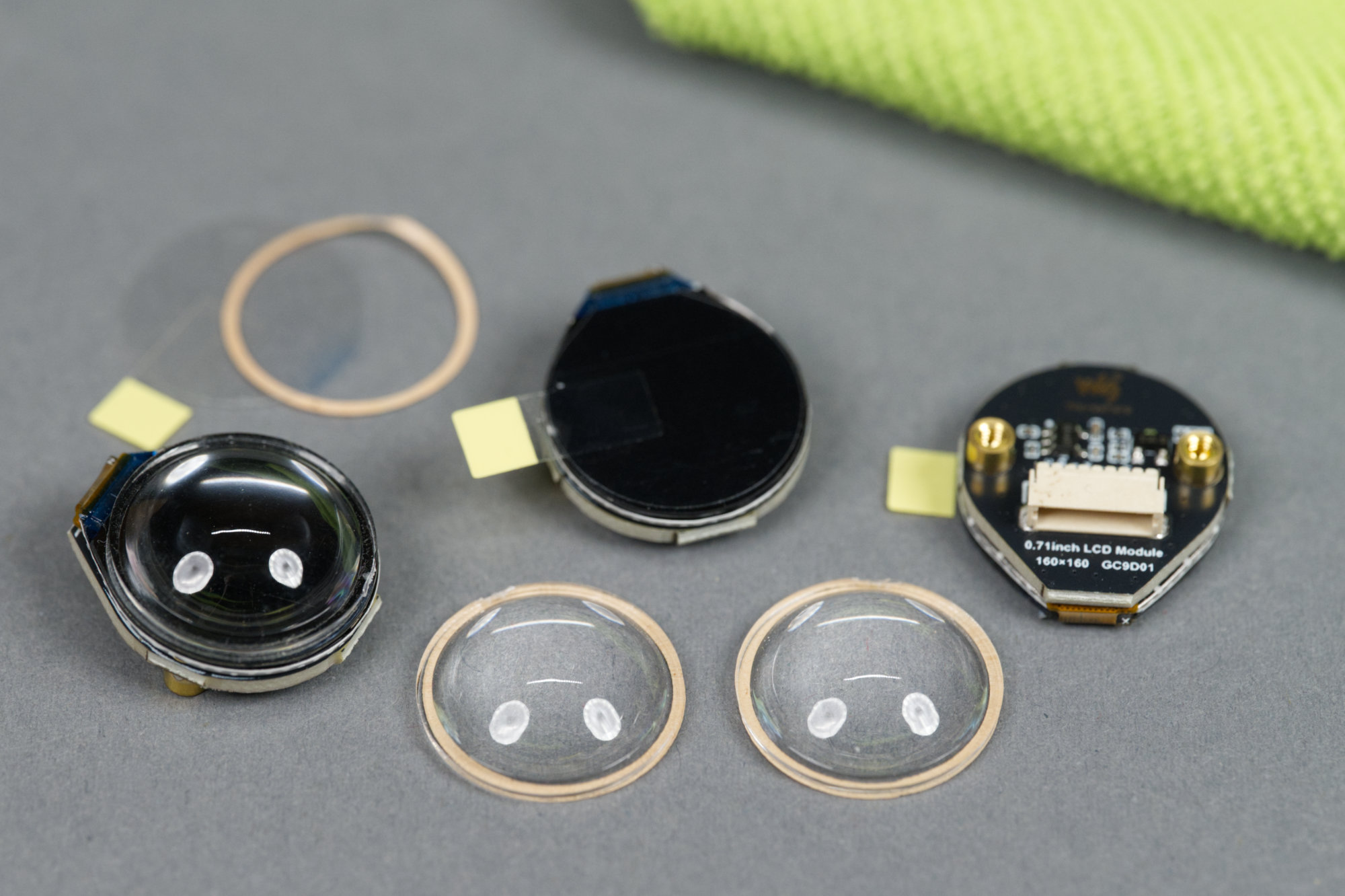
LCDs and acrylic lenses. One LCD has an acrylic lens affixed to it.
Use a dry, lint-free cloth to clean any debris on the backside of the lenses. Remove the protective film from the LCD and the adhesive ring on the lens. Gently press the lens onto the LCD. Repeat for all three LCDs.
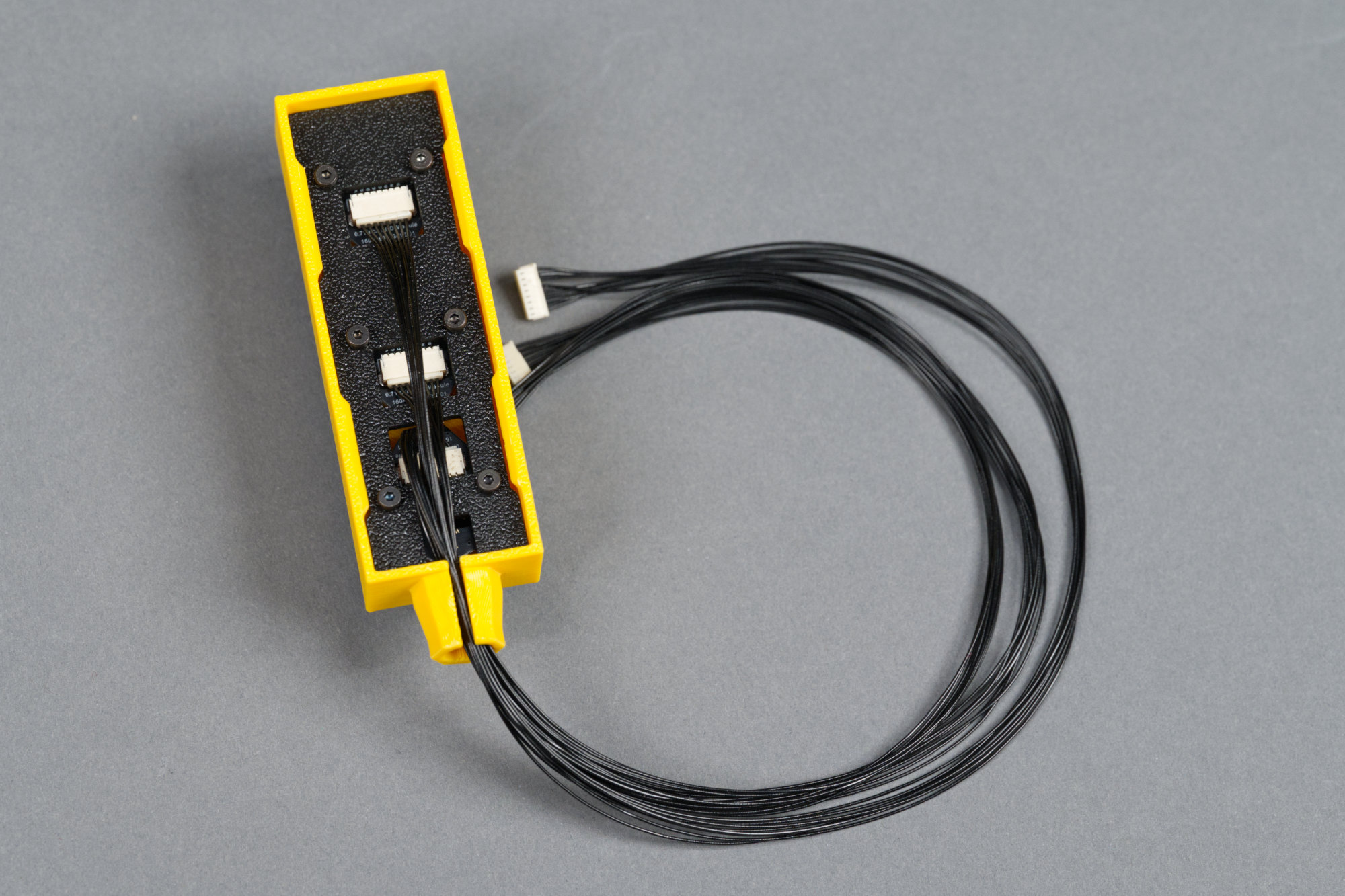
2) Connect cables to displays and route cables through frame.
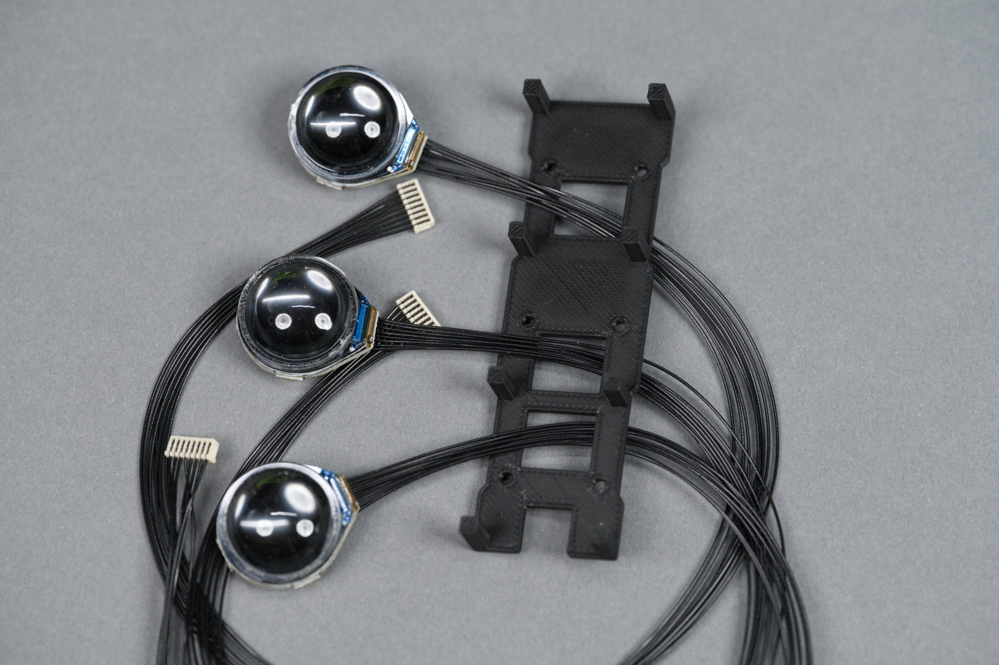
Cable assemblies connected to displays and routed through mounting plate.
Connect the cables to the displays then route the free end through the display mounting plate as shown above.
3) Mount the displays to the frame using the six M2 x 4 mm screws.
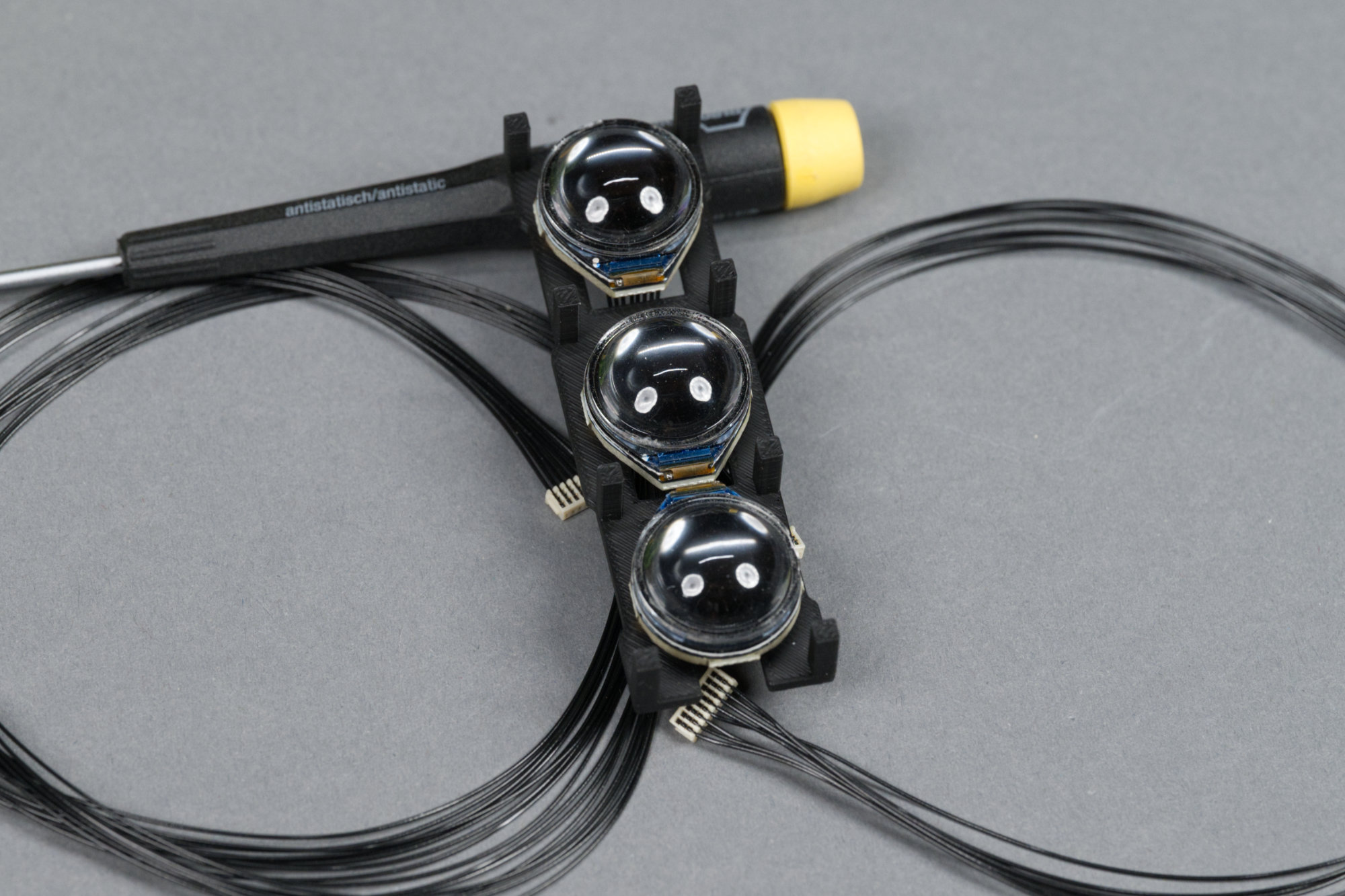
The displays are mounted to the backing plate and the cables are routed through the plate and behind the displays.
Mount the displays to the frame using the M2 x 4mm screws. The bottom of the frame has a notch cut out of it. The top two displays are mounted right-side up with their connectors pointed toward the bottom of the frame. The bottom display is mounted upside down with its connector pointed toward the top of the frame. The connectors at the opposite ends of the cables can be labeled with the positions of the display if wanted.
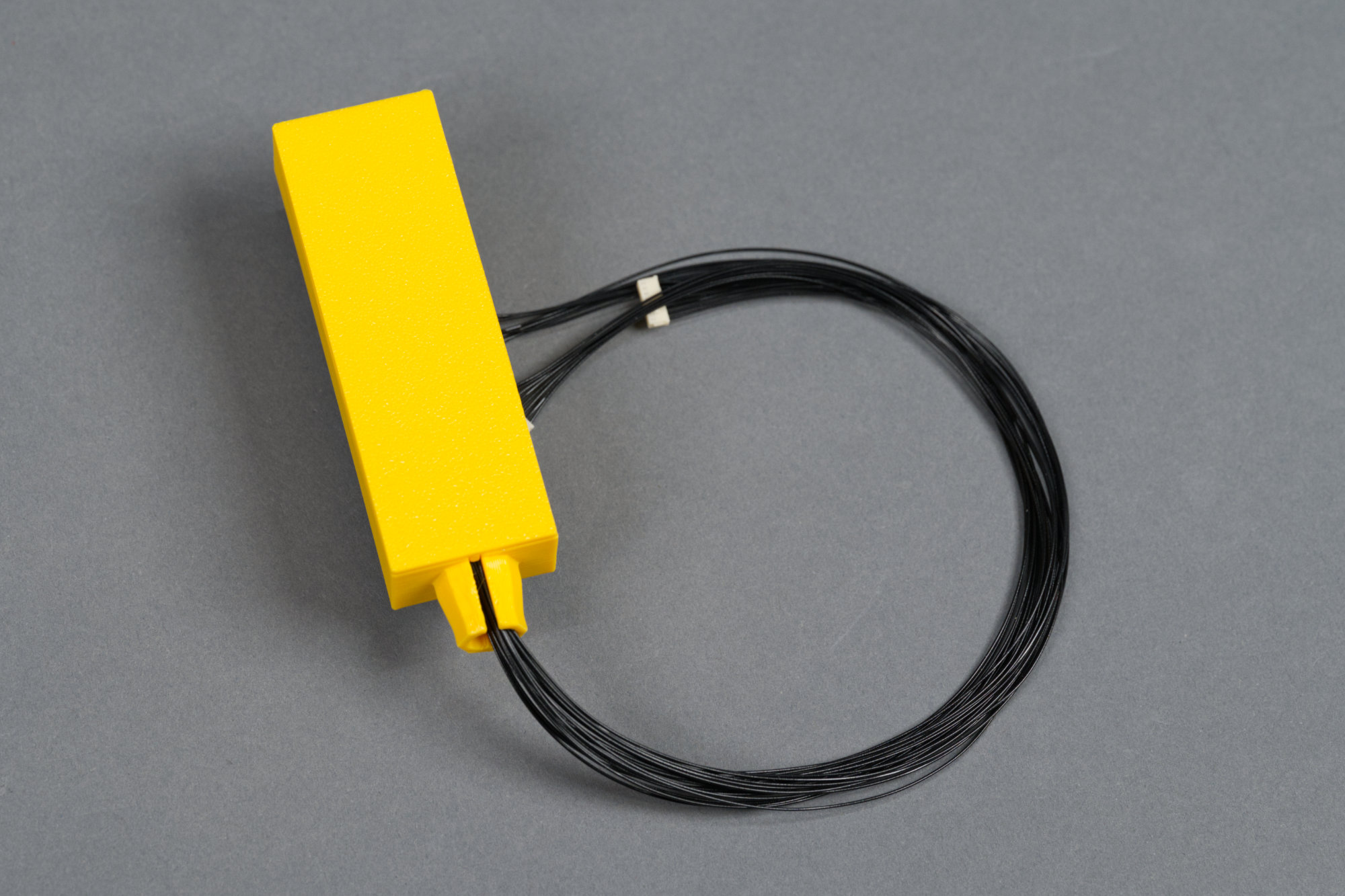
4) Place the frame into the signal body with the notch to the bottom.
Mounting plate and displays placed in the signal body housing.
Place the mounting plate and displays into the signal housing and route the cables toward the bottom of the housing and out through the slot on the bottom of the housing.
5) Carefully snap the back on to the signal body while avoiding pinching any wires.
Rear lid placed on signal body with display cable assemblies running out the bottom.
While holding the cables out of the way, snap the signal back onto the rear of the signal housing.
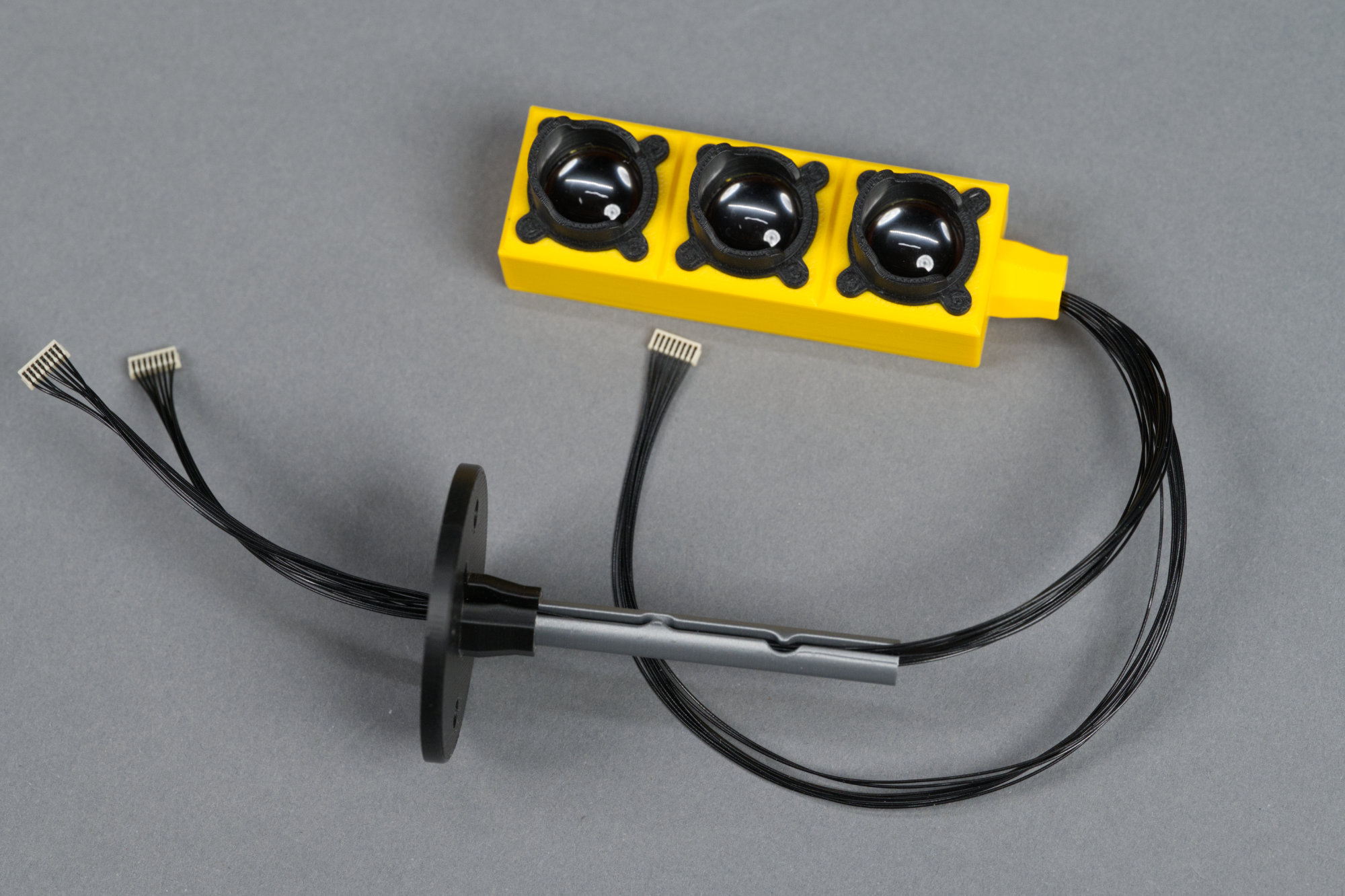
6) Working one cable bundle at a time, route the wires from the signal body through the signal mast.
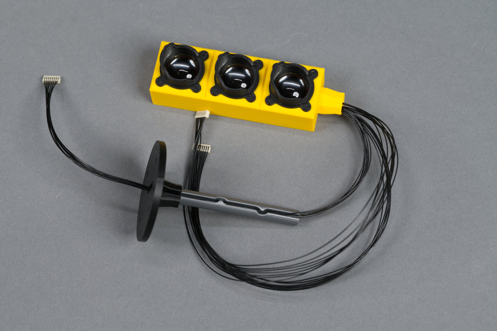
First display cable assembly routed through the signal mast.
Route a connector from the top of the stand through to the bottom of the stand then gently ease the cable’s conductors into the mast. This should be done without using any tools to avoid breaking or nicking any of the conductors.
Second display cable assembly routed through the signal mast.
Repeat the process for the second cable assembly.
Third and final display cable assembly routed through the signal mast.
And finally, the third cable assembly.
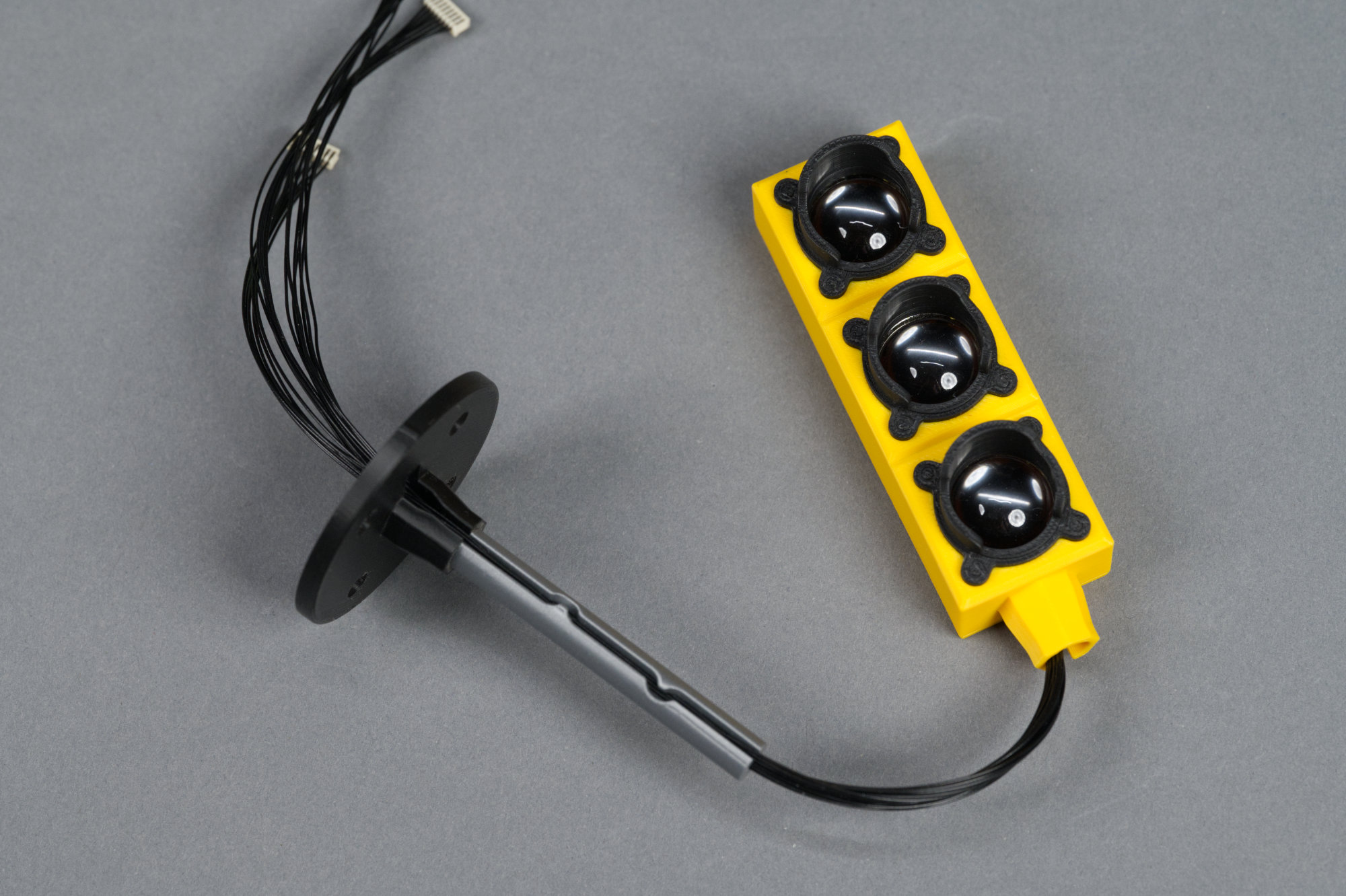
7) Gently slide the signal mast up the wires until the signal body is firmly seated on the mast.
Signal body firmly seated on signal mast with cables routed out the bottom of the mast.
Gently slide the signal mast up along the wires until it is seated firmly in the base of the signal housing. You may need to gently pull on the wires from the bottom of the stand as you do this.
8) Place the four rubber feet on the bottom of the signal platform.
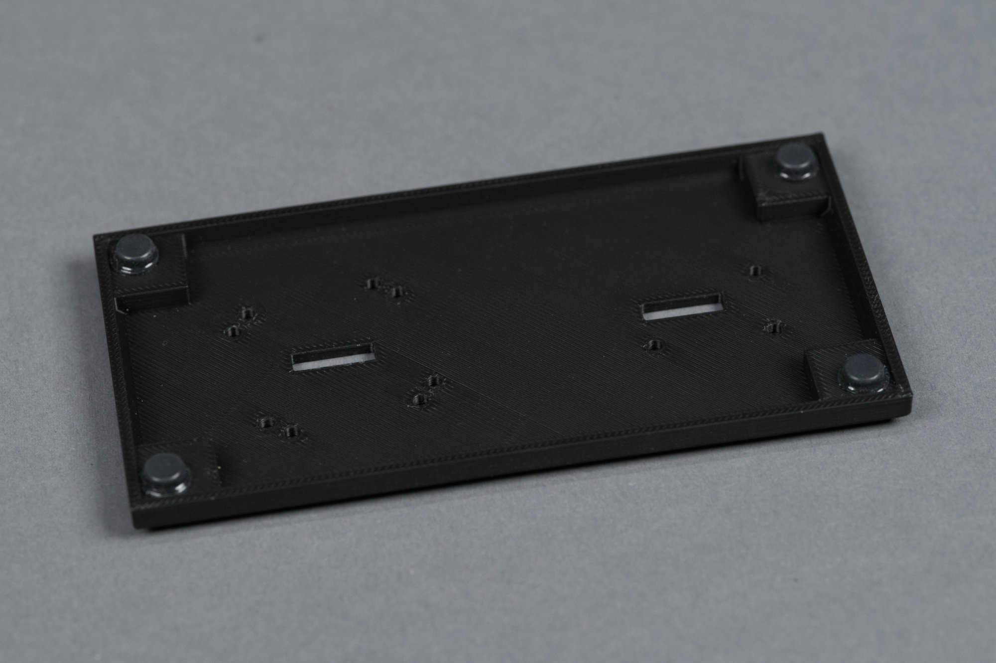
Bottom of the platform with rubber feet placed on the raised area in each corner.
Stick a rubber foot on the raised square in each corner of the underside of the signal platform.
9) Install antenna on controller cabinet.
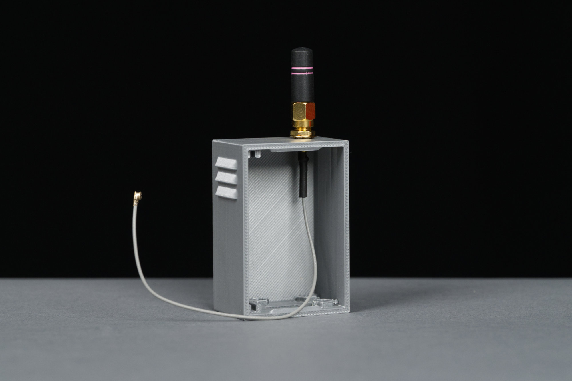
The controller cabinet with the coax cable assembly and antenna mounted.
Remove the nut and washer from the coax cable assembly. Push the RP-SMA connector from the inside through the top of the controller cabinet and secure using the previously removed nut and washer. Finger tight is good enough. Screw the antenna on to the RP-SMA connector. Again, finger tight is good enough.
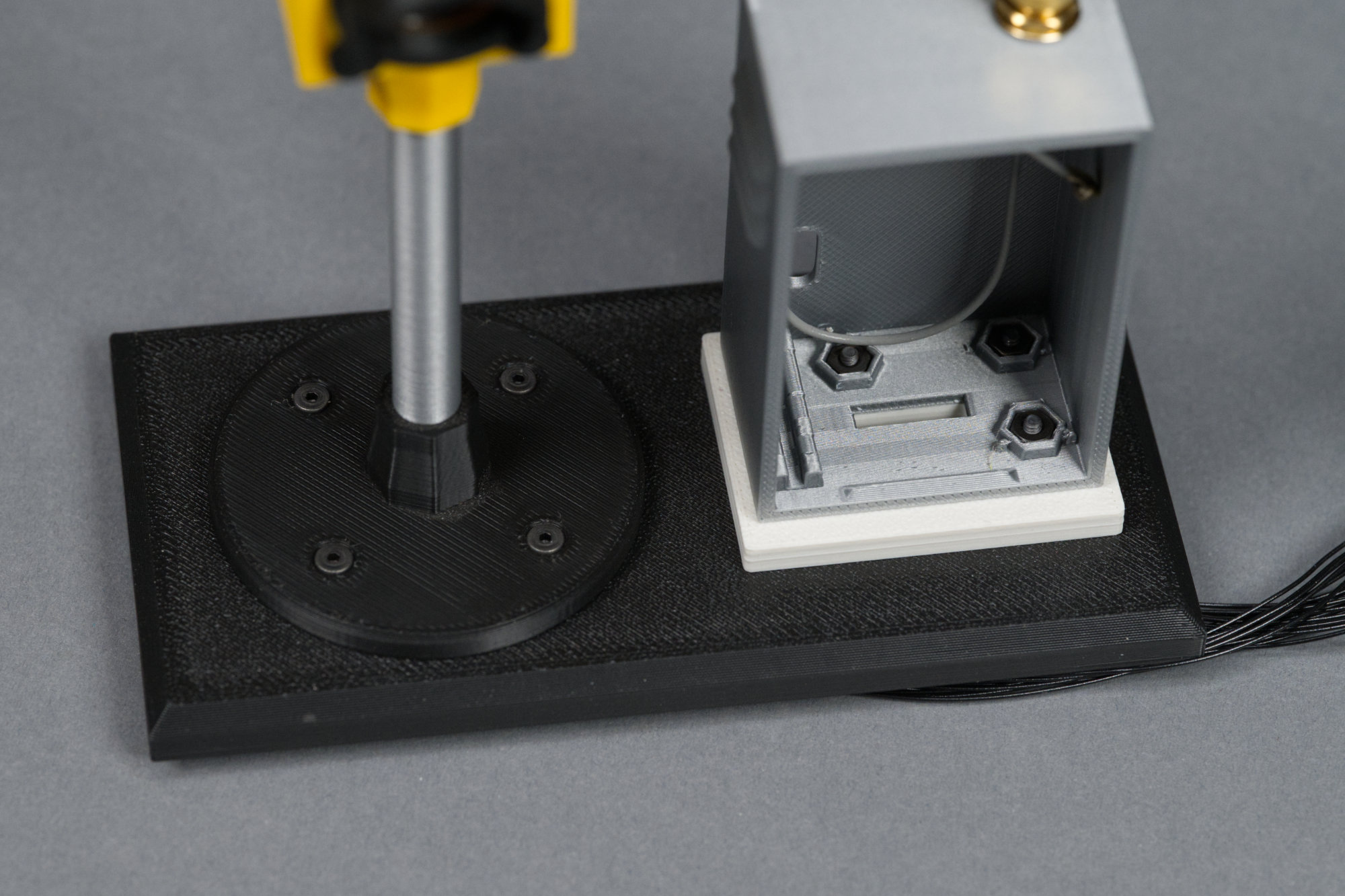
10) Install the controller cabinet and concrete pedestal on the signal platform.
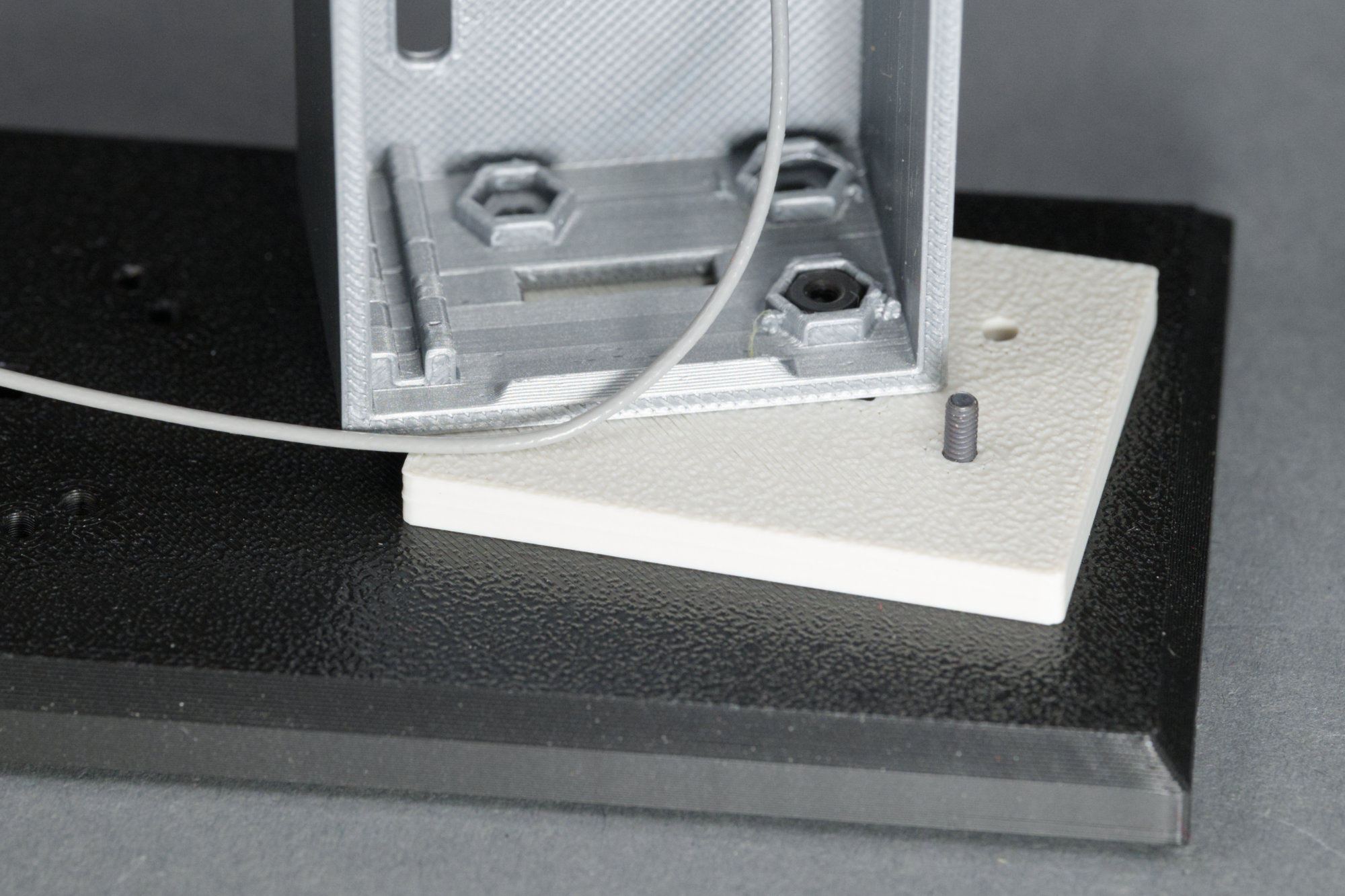
Attaching the front right corner.
Use the three 2-56 x 7/16″ pan head screws to secure the signal cabinet and pedestal to the platform. The screws feed up from the bottom of the platform and their is a recess inside the cabinet for each of the three nuts. The photo above shows the orientation of the platform, pedestal, and cabinet.
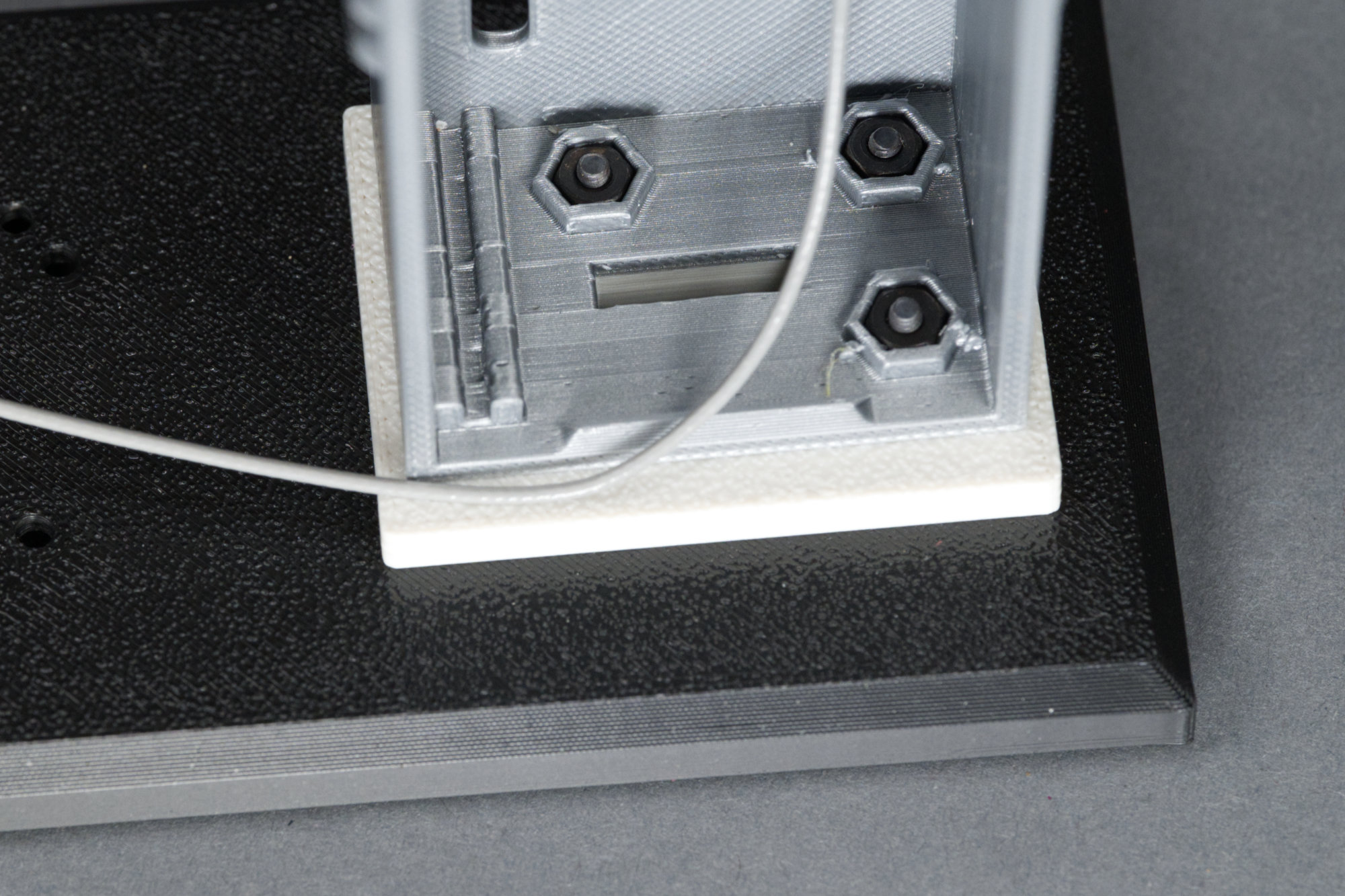
All three corners secured.
The photo above shows the cabinet and pedestal secured to the platform.
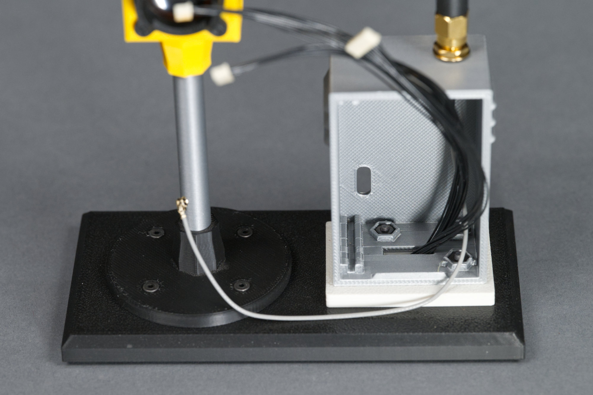
11) Route the cables and connectors from the signal body and mast through the slot in the signal platform.
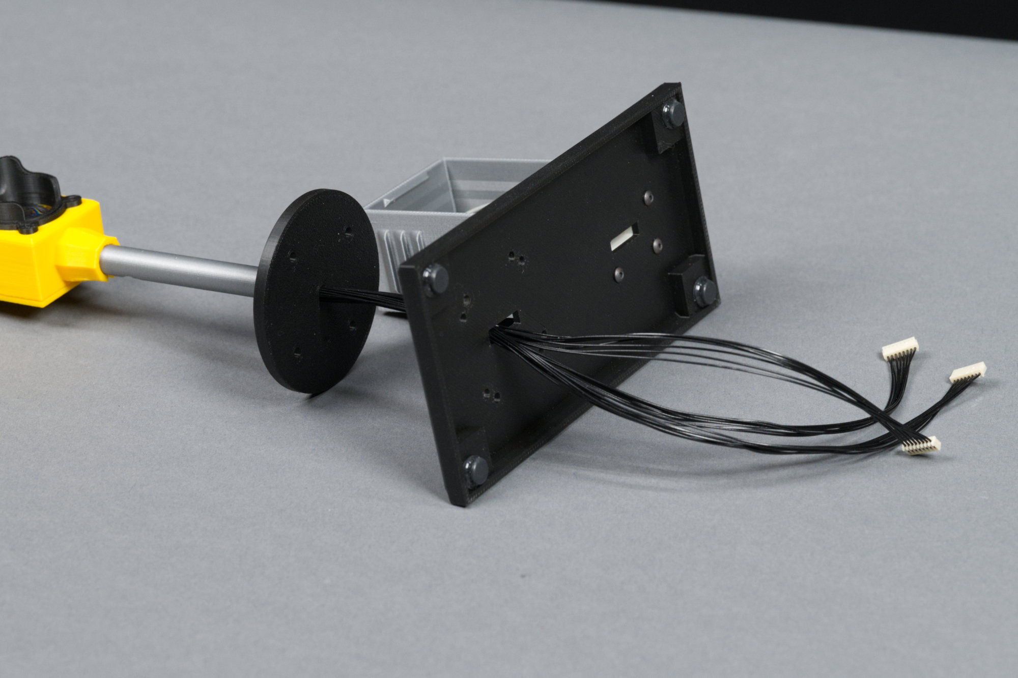
Cables routed through the left side of the platform.
Route the cables from the signal stand through the rectangular slot on the platform as shown above.
12) Install the signal body and mast on the signal platform.
Mast attached to platform.
Use the 2-56 x 5/16″ flat head screws and 2-56 nuts to mount the signal, body, and mast to the platform.
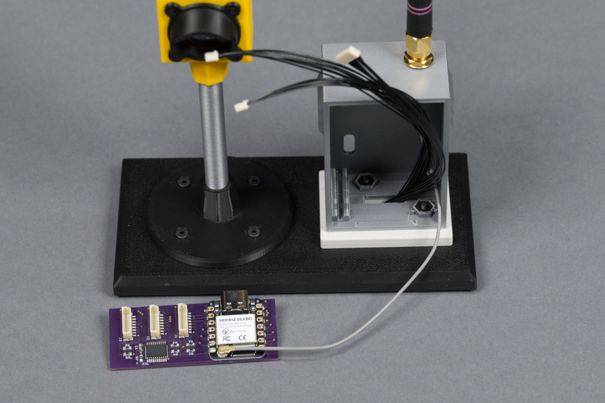
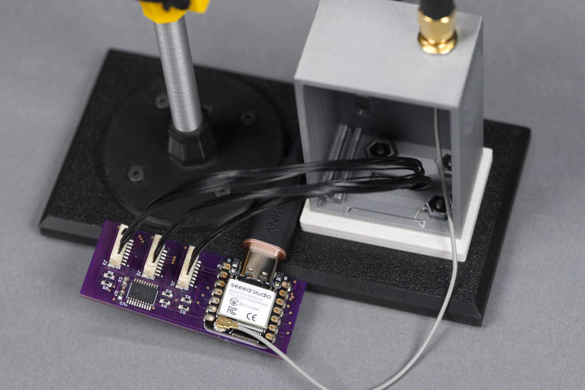
13) Route the cables and connectors underneath the signal platform, through the slots, and into the controller cabinet.
Pull the display cables through the platform and pedestal and into the controller cabinet.
Route the cables back up through the platform and into the controller cabinet. Pull them out toward the front of the cabinet to ease connecting them to the controller board in the next step.
14) Connect coax to controller board.
Antenna connected to controller board.
I hate U.FL connectors but we’re stuck with them. Carefully connect the U.FL connector on the cable assembly to the U.FL connector on the XIAO moduule. It just presses in place but can be tricky to align.
15) Connect signal cables to controller board and test everything.
Display cables connected to the controller.
Connect the signal cables to the controller board. Plug the controller board into a USB port or power adapter. Verify the displays are working and in the right order. My CircuitPython script in the code section above displays red on the top display, yellow on the middle, and green on the bottom. If any displays are out of order, power down the board, swap cables as needed, and test again.
16) Slide the controller board into the controller cabinet and tuck any excess cable inside the cabinet.
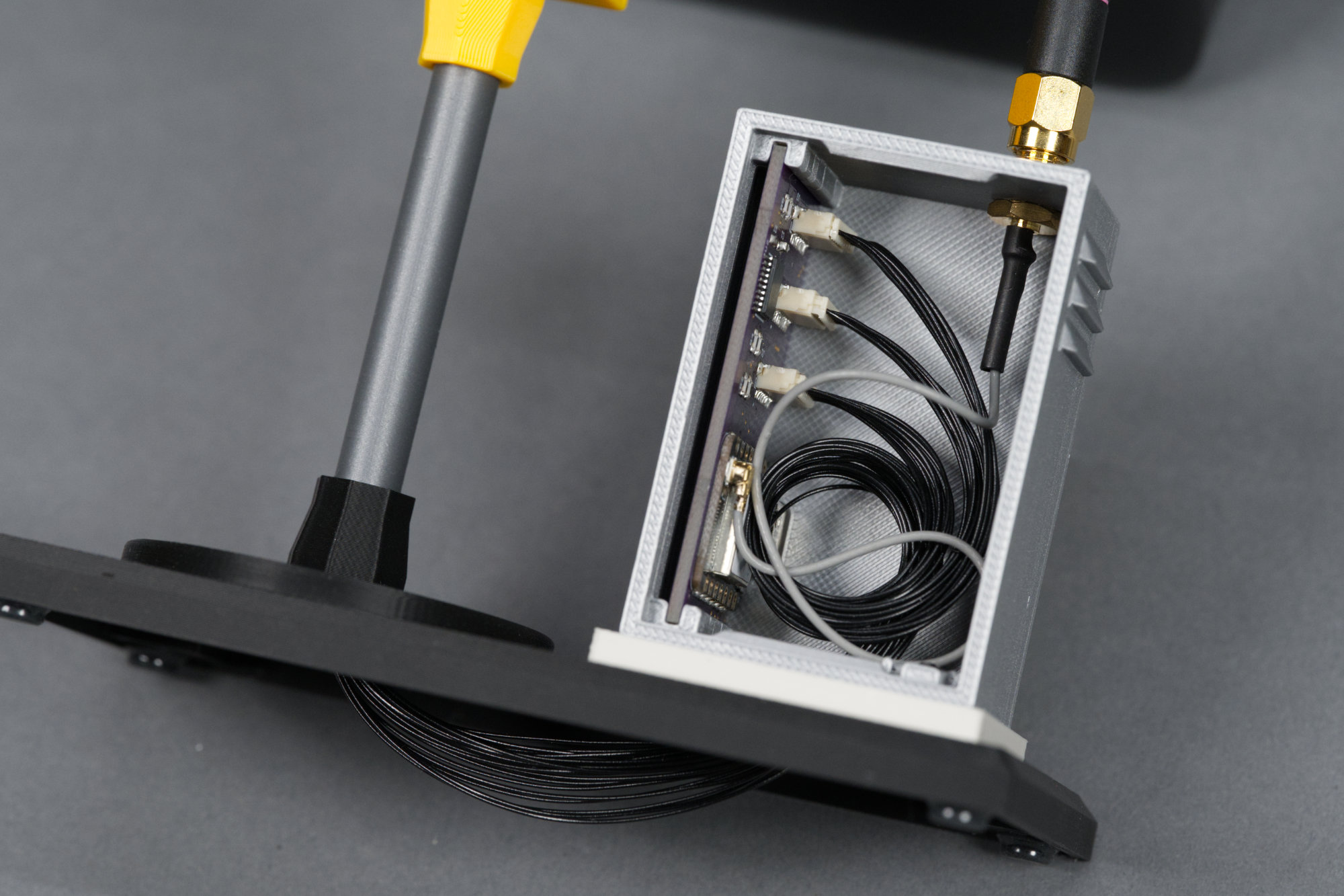
Controller cables and board neatly placed in cabinet.
I twisted the board around once to get the wires to coil in the back of the cabinet. Also, if any wires under the platform prove unruly, they can be tacked in place with a bit of tape applied across the wires and stuck to the bottom of the platform.
17) Snap the lid on to the controller cabinet.
The door snaps on to the cabinet.
The last step is to press the cabinet door into place on the controller cabinet. Congratulations!
Wrap Up
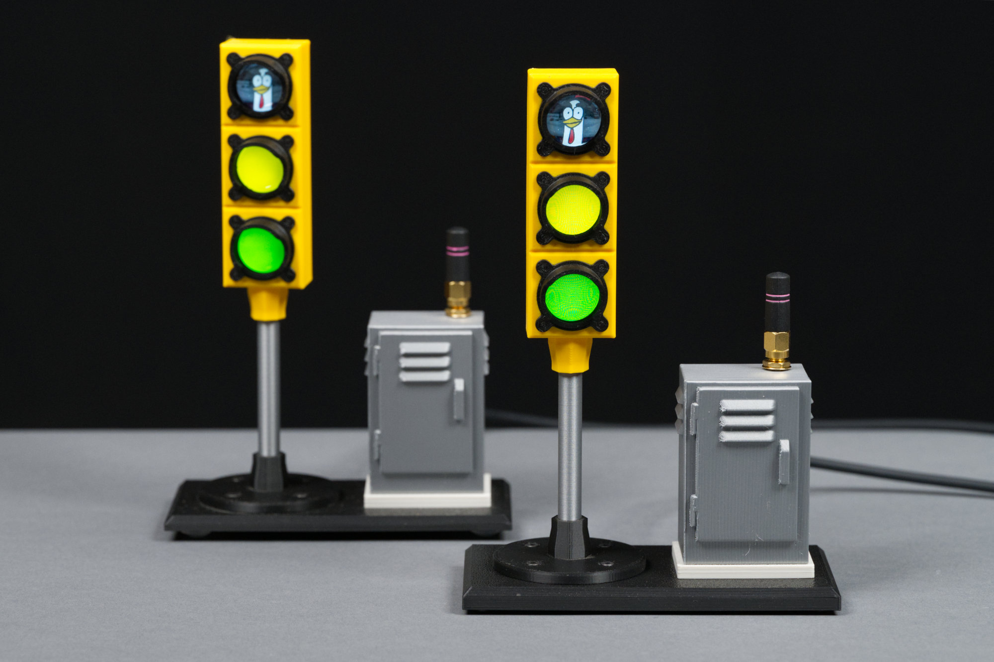
And then there were two! Original prototype in the background on the left and the final model in the foreground on the right.
That’s! Thanks for reading along or at least looking at all the pictures. If you chose to build your own LCD traffic signal, I hope it was a fun and rewarding project!
Downloads
All the files for the project can be downloaded using the links below.
3D Print Files
- signal_hoods_and_body.3mf
- lcd_mounting_plate.3mf
- signal_body_rear_lid.3mf
- stand.3mf
- platform.3mf
- pedestal.3mf
- cabinet.3mf
- cabinet_door.3mf