I’ve had three Color Kinetics ColorBurst 6 RGB LED fixtures in my front yard for about ten years now. They’ve survived numerous winter snowstorms and spring monsoons. Recently one of the three fixtures started taking on water and the blue and green channels began flickering. Having served its useful life in the front yard, I promptly removed it and replaced it with a new fixture. This left me with a water logged fixture that almost but not quite worked. Time to drain the water and do a proper teardown. Read on to see how a commercial-grade RGB LED light fixture works.
Background
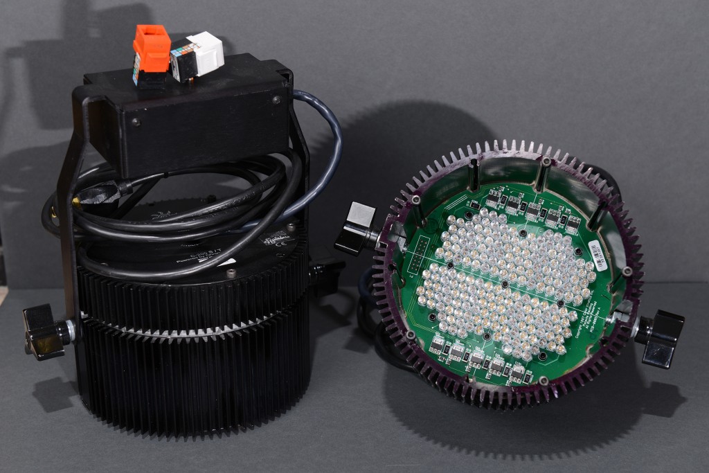
If you’re not familiar with Color Kinetics or their products, they created some of the first RGB LED lighting fixtures shortly after the invention of the blue LED. Their earliest products, like the C200 fixture shown above, were based on multiple strings of ordinary 5mm red, green, and blue LEDs connected in series with each string driven at about 20mA.
Multiple strings of the same color are then connected in parallel. Each group of LEDs of the same color is connected to a driver and that driver is connected to a microcontroller. The microcontroller pulse width modulates the LEDs to control their brightness in response to a DMX-512 signal from a light board or other DMX controller. The fixtures run on +24VDC supplied by an external power supply.
The ColorBurst 6 fixture shown above is one of CK’s 2nd generation fixtures and one of the first lighting products to use Lumileds’s 1 Watt Luxeon emitters. This fixture debuted around the 2002 time frame. It’s much more sophisticated than the earlier design. It’s (mostly) waterproof and uses strings of red, green, and blue high-power LEDs.
The mounting bracket permits the light to be aimed. Exiting from the bottom of the bracket are three wires: power (+24VDC), ground, and data. These connect to an intelligent power supply that both supplies power and relays data from either a DMX or Ethernet network to the fixture. According to the data sheet, the fixture consumes about 25W with all three channels at full brightness.
Covering the front of the fixture is either a clear or frosted piece of tempered glass. The fixture with the clear glass has a beam angle of 10° and the fixture with the frosted glass has a beam angle of 21°. The tempered glass is permanently bonded to the painted aluminum enclosure using a waterproof sealant.
Literally Cracking It Open
The first step to disassembling the broken fixture was to remove the tempered glass from the front of the fixture. After ten years of exposure to the elements, the white paint under the sealant began to flake and allowed water to penetrate into the broken fixture. Even though the seal was leaking, the glass was still tightly bonded to the aluminum housing.
To remove the glass, I donned some safety glasses and gloves and used a large screwdriver and hammer to shatter the tempered glass. A bit of scraping removed the paint, sealant, and any remaining glass shards around the perimeter. A quick rinse with the garden house removed the dust, dirt, and broken glass inside the enclosure.
Components and Block Diagram
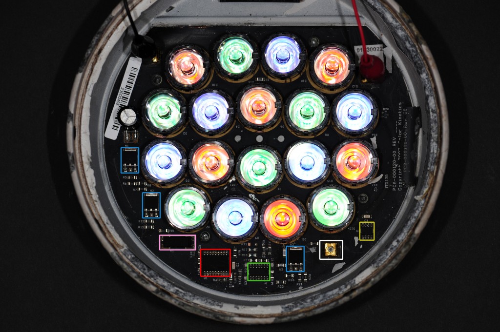
The internals of a ColorBurst 6 RGB LED lighting fixture with key compoents highlighted. The description of each highlighted component is in the text accompanying this photo.
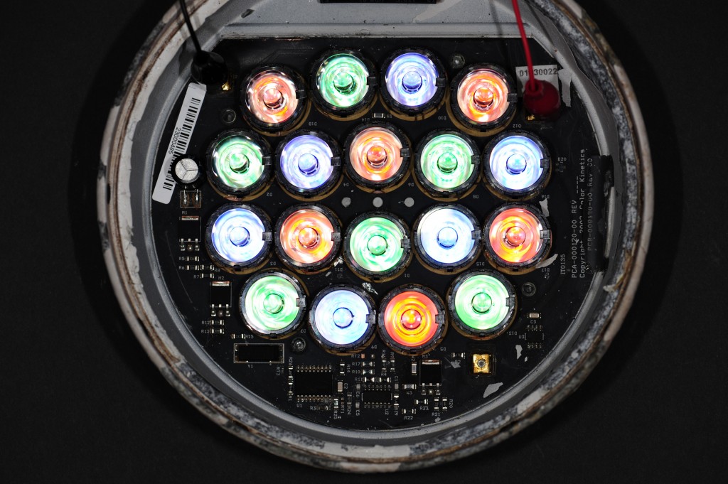
The fixture has six red LEDs, six green LEDs, six blue LEDs, three integrated circuits, three MOSFETs, one diode, and numerous passives. These components are soldered to an aluminum core PCB which has better heat dissipation properties than a normal FR4 PCB. In the photo above the various key components are highlighted in the following colors:
- Red: Microchip PIC16F628 flash-based, 8-bit CMOS microcontroller. The PIC is the brains of the operation. It receives brightness commands from the power / data supply and sets the brightness of the red, green, and blue LEDs appropriately.
- Yellow: National Semiconductor LM78L05 +5V linear regulator. A small diode is connected in series between the +24V power input and the regulator to lower the power dissipation in the regulator.
- Blue: Three Fairchild FQD7N10L N-Channel QFET MOSFETs.
- Green: Texas Instruments LMH6644 75mA rail-to-rail quad output amplifier, aka op amps.
- Pink: a 20MHz crystal.
- White: quick disconnect terminal for data input. The black alligator clip is connected to the ground terminal. The red alligator clip is connected to the +24VDC power terminal.
The LEDs are not highlighted but since they’re illuminated, you can see the position and color of each LED. These are most likely Lumileds Luxeon 1W emitters. All LEDs of the same color are connected in series. The anode of the first LED in each series is connected to +24VDC and the cathode of the last LED in each series is connected to the drain of one of the three MOSFETs.
The power supply voltage is +24V. The forward voltage of red LEDs is about 2V and the forward voltage of the green and blue LEDs is about 3.5V. The combined forward voltage of each string of six LEDs is well below the power supply voltage thus permitting the LEDs to fully illuminate when the MOSFET is in an on state.
The aluminum core PCB is bonded to the aluminum enclosure and serves to conduct heat from the LEDs to the enclosure where it can be dissipated into the atmosphere via convection.
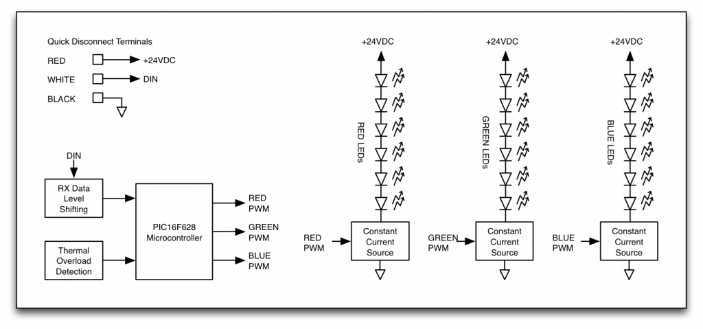
After identifying the components and reading a few of their patents, I’m beginning to get an idea of how their fixture might be put together. Below is my block diagram.
Let’s examine each of the major functional blocks in detail.
Power and Communications
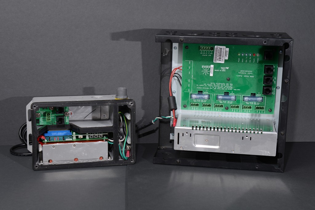
The photo above shows two different power supplies. The smaller gray 60W power supply can drive two ColorBurst 6 fixtures. The larger black 150W power supply can drive up to six ColorBurst 6 fixtures. The 60W supplies are available in preprogrammed, DMX, or Ethernet configurations. This one is a preprogrammed supply. The 150W supplies always support both DMX and Ethernet. Both power supplies are universal input DC switching power supplies and convert whatever the local line voltage and frequency is to +24VDC to power the fixtures.
Besides supplying power, the power supplies relay brightness levels from a DMX or Ethernet-based lighting network to the lighting fixtures. From some prior reverse engineering work, I determined that the protocol to the lights is basically DMX except that the signalling used is a single-ended signal that swings between ground and +24V instead of the normal RS-422 differential signal.
When a power supply is on a DMX network, it only has to change the voltage levels and can send the signal to the light with no or minimal processing. When a power supply is on an Ethernet network, it receives UDP packets on its Ethernet interface, parses the light levels out of the received UDP packets, then converts them to the +24V version of DMX used by the fixtures.
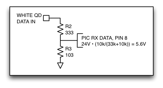
At the light, the +24V DMX signal is received on the quick disconnect terminal highlighted in white. This signal runs through a voltage divider constructed from 33k and 10k resistors to produce a signal that is just barely within the microcontroller’s absolute maximum ratings. This signal is fed to the UART RX pin on the PIC16F628 microcontroller, pin 8. The UART TX pin, pin 9, is not connected. The schematic above shows the data input circuit and its connection to the PIC microcontroller.
The Device Enumeration Mystery
The unconnected UART TX pin opened up a mystery. When connected to an Ethernet network, the power supplies can determine and report the serial numbers of the connected lighting fixtures back to the host computer. How can the power supplies do this when there’s no return path for data from the light fixture back to the power supply?
But there is a return path—the current consumption of the fixtures. My hypothesis was that the power / data supply selectively told fixtures with certain bits set or clear in their serial numbers to turn off or on. The power / data supply would then measure the current consumption to determine if a connected light was in fact off or on. Other than that, the search should work like a normal DMX/RDM binary search for fixtures.
To test my hypothesis, I used Color Kinetic’s QuickPlay Pro software to instruct my Ethernet power / data supply to enumerate the connected lights while the light was powered by the power / data supply. It found the light and reported the correct serial number. I then conducted a second experiment. I left the data and ground connections to the power / data supply but used a bench supply to supply the power to the fixture. I instructed the software to enumerate the connected lights again. Nothing. Not 100% definitive proof that my hypothesis was correct but good enough proof for me for now. I did not examine the enumeration protocol in greater detail.
Constant Current Sources
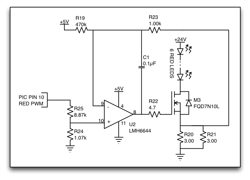
The next step was to figure out how the constant current sources worked. I used my bench DMM’s two-wire ohmmeter and continuity test functions to ohm out the circuit. This can be a tedious process but fortunately the constant current sources were relatively simple. The figure below shows the schematic I created for the red channel of the fixture. The green and blue channels are identical. Much to my disappointment, this is a linear regulator circuit. I would have preferred to have seen some sort of a much higher efficiency switching regulator circuit.
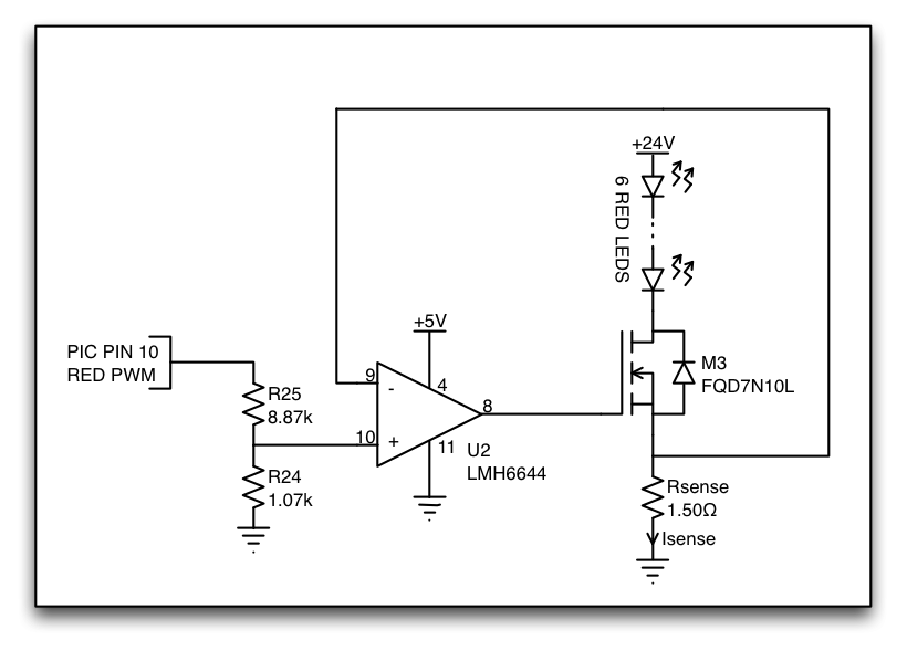
For the purposes of our analysis, we can treat R19 and C1 as opens and R22 and R23 as shorts. R19 serves to shut down the constant current source in case of an open in the current sense circuit. C1, R22, and R23 will have very little current running through them in the steady state. This makes C1 an open and the voltage drop across R22 and R23 will be almost zero. R20 and R21 in parallel act as a current sensing resistor. Their combined resistance is 1.5 ohms. Let’s replace them with a single resistor called Rsense of 1.5 ohms. The simplified schematic below makes analysis of the circuit much simpler.
Let’s figure out the voltage, V(-), at the inverting terminal of the op amp. In an ideal op amp, no current will flow into its inputs. These means that the current through each LED, the current through the MOSFET from its drain to its source, and the current through the sense resistor must all be equal.
From Ohm’s law, the voltage across the current sense resistor will then be equal to the current through the resistor, Isense, multiplied by the resistance of the resistor, Rsense. This is the same voltage as at the inverting terminal of the op amp:
V(-) = Vsense = Isense • Rsense
Rearrange this to find the current for a given voltage at the inverting terminal:
Isense = V(-) / Rsense
The current through the LEDs is the same as the current through the sense resistor:
Ileds = V(-) / Rsense
An ideal op amp will adjust its output to keep the voltage, V(-), at its inverting terminal equal to the voltage, V(+), at it noninverting (+) terminal:
Ileds = V(+) / Rsense
The voltage, V(+), at the noninverting terminal of the op amp depends on if the PIC microcontroller is driving its output pin low (0V) or high (5V). In the case of the microcontroller driving its output pin low, the voltage, V(+), at the noninverting terminal of the op amp will be:
V(+)lo = 0V • (1.07kΩ / (1.07kΩ + 8.87kΩ) = 0V
And the LED current when the PIC drives it output low will then be
Ileds = V(+)lo / Rsense
Ileds = 0V / 1.5Ω
Ileds = 0A
In other words, when the output pin of the microcontroller is low, no current will flow through the LEDs and they will not be illuminated. In the case of the microcontroller driving its output pin high, the voltage, V(+), at the noninverting terminal of the op amp will be:
V(+)hi = 5V • (1.07kΩ / (1.07kΩ + 8.87kΩ) = 0.538V
And the LED current when the PIC drives it output high will then be
Ileds = V(+)hi / Rsense
Ileds = 0.538V / 1.5Ω
Ileds = 0.359A
In other words, when the output pin of the microcontroller is high, the current through the LEDs will be about 359mA. From looking at data sheets for various 1W LEDs, we expect the drive current at full brightness to be about 350mA. The calculated values match the expected values!
To summarize, when the microcontroller output pin is low, the LEDs are off because no current flows through them. When the microcontroller output pin is high, the LEDs are on at their full brightness because their maximum rated forward current is flowing through them.
Dimming
Even though the microcontroller can only turn each color of LEDs completely off or completely on, this fixture is still capable of setting each color of LEDs to one of 256 different levels of brightness. This level control is done by altering the amount of time a channel of LEDs is on relative to the amount of time that the same channel of LEDs is off. If the switching of the LEDs off and on occurs fast enough, the eye will see the average level of the LEDs rather than the individual periods where the LEDs are either off or on. If the switching is not quite performed fast enough, the eye will see the average color but may also perceive an annoying flickering. When all three channels are mixed (such as by pointing the fixture at a white wall), the fixture can generate any of 16,777,216 colors.
One technique used to switch LEDs on and off quickly to dim them is pulse width modulation (PWM). In PWM, a fixed period of time is divided into a portion of time where the LEDs are on and another portion of time where the LEDs are off. This fixed period of time is usually referred to by its reciprocal, the PWM frequency. The portion of time on relative to the entire period is referred to as the duty cycle. In the figure above, (A) represents the LEDs at 25% power, (B) represents the LEDs at 50% power, and (C) represents the LEDs at 75% power. (A), (B), and (C) all have the same PWM frequency but the duty cycle in each varies by 25%. The PWM frequency generally needs to be at least 120Hz to prevent annoying flickering.
The ColorBurst 6 fixture does not use pulse width modulation dimming! Both the frequency and duration of the on time and off time vary depending on the programmed brightness level. For example, at a level of 1 (out of 255), the LEDs are on for 400ns every 1.69ms. At a level of 2 (out of 255), the LEDs are on for 400ns every 0.792ms. At higher brightness levels, the LEDs are switched on or off every 26.4µs. At this 26.4µs interval, the LEDs will either be turned on for 26.4µs, turned off for 26.4µs, turned on for 400ns / off for 26µs, or turned on for 1600ns / off for 24.8µs depending on the programmed brightness level. Brighter levels have more of the on for 26.4µs periods; dimmer levels have more of the off for 26.4µs periods.
I have not worked out the exact on times / off times / frequencies for all the different levels. I may do this in the future but it’s really not needed to understand the operation of the fixture.
Two other points to consider when dimming LEDs:
- An LED’s color will drift depending on both the forward current through the LED and the die temperature. You can dim an LED by changing the current through the LED but the color may shift as the brightness levels are changed. For more consistent color, it’s better to drive the LEDs with a fixed current and dim the LEDs by rapidly switching that current off and on. You’ll still have some color shift from die temperature changes as the duty cycle is increased but they’ll be less than the color shift caused by varying the current.
- This lighting fixture supports 256 levels of brightness for each of three primary colors. These levels are linear in that, for example, the 128th level should be perceived as 50% brightness by a human audience; the 64th level as 25%, the 192nd as 75%, etc. Internally, the fixtures use a gamma correction algorithm to map the programmed level to a duty cycle that appears to be that brightness to humans.
To implement the gamma correction algorithm and create 256 levels of perceptually-linear brightness, the underlying dimming technique must support many more levels of brightness than 256. The ColorBurst 6 dimming is most likely done in software at interrupt time. Since there aren’t enough clock cycles available to do higher than about 10-bit resolution PWM in software, the fixture varies both the frequency and duration of the on times to achieve an accurate perceptually-linear dimming curve.
Thermal Overload Detection
The ColorBurst 6 fixture has a built-in over temperature circuit. When the fixture becomes too hot, the microcontroller sets the fixture to the dimmest red color for thirty minutes to allow the fixture to cool down. The circuit for this is quite simple as shown in the schematic below.
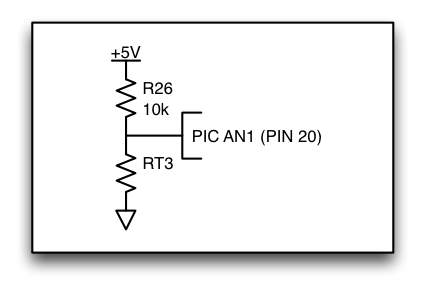
RT3’s resistance decreses as the board temperature increases. The microcontroller uses this sensor to detect over heating and shut down the fixture.
R26 and RT3 form a voltage divider. RT3 is a thermistor of some sort. In my cool fixture at room temperature the resistance was about 10.0kΩ. After running the fixture for five minutes, the resistance had decreased to 7.5kΩ. The output of the voltage divider is connected to the AN1 input of the PIC microcontroller. This pin is an input to the PIC’s analog-to-digital converter. As the resistance of the thermistor changes in response to the board temperature, the voltage on the pin changes. The microcontroller periodically samples this voltage using the analog-to-digital converter and at a certain threshold enables the fixture’s thermal protection mode. I could force the fixture into its thermal protection mode by momentarily grounding pin 20.
Additional Resources and Footnotes
I hope you enjoyed reading this teardown of my waterlogged Color Kinetics ColorBurst 6 RGB LED light fixture. The following additional resources are suggested reading if you’d like to learn more about this fixture.
- ColorBurst 6 product guide (on CK website, for the latest version of fixture)
- Color Kinetics has a ton of patents on their RGB LED lighting fixtures. Many of the details of their products are spelled out in these patents. One of the earliest patents is #6,016,038, for a “Multicolored LED lighting method and apparatus.” This patent describes the technology in their C200 light fixtures.
Both Color Kinetics and Lumileds are now owned by Philips. I’m not sure of the exact acquisition date for either company.

